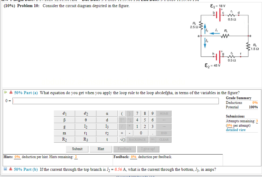
44 consider the circuit diagram depicted in the figure
Answered: 47. For the circuit depicted in Fig.… | bartleby For the circuit depicted in Fig. 10.58, (a) redraw with appropriate phasors and impedances labeled; (h) employ nodal analysis to determine the two nodal voltages v (t) and vz (1). 2F 400 mF 100 mI ( )2 cos 10t A 3 cos 101 A ( 5 2 I FIGURE 10.58 ele Question Solve and show solution fullscreen Expand Transcribed Image Text 47. Solved Consider the circuit diagram depicted in the figure. - Chegg Best Answer 93% (14 ratings) Transcribed image text: Consider the circuit diagram depicted in the figure. What equation do you get when you apply the loop rule to the loop abcdefgha, in terms of the variables in the figure? If the current through the top branch is I_2 = 0.47 A, what is the current through the bottom. I_3 in amps?
A capacitor of capacitance C is charged to potential ... - Toppr Ask Click here👆to get an answer to your question ️ Paragraph for Question no. 45 and 46 Consider a simple RC circuit as shown in figure 1. Process 1: In the circuit the switch S is closed att cut the switch S is closed at t - and the capacitor is fully charged to voltage (ie, charging continues for time T >> RC). In the process some occurs across the resistance R.
Consider the circuit diagram depicted in the figure
Kirchhoff S Circuit Laws Questions and Answers - Study.com Consider the circuit diagram depicted in the figure. (a) What equation is obtained when the loop rule is applied to the loop abcdefgha, in terms of the variables in the figure? \\(b) If the current... Answered: Problem 7: Consider the circuit diagram… | bartleby B6. Transcribed Image Text:) Problem 7: Consider the circuit diagram depicted in the figure. E = 18 V 0.50 R 2.50 4 R, R 1.50 0.50 E, = 45 V. Transcribed Image Text: to Part (a) What equation do you get when you apply the loop rule to the loop abcdefgha, in terms of the variables in the figure? d 4 5n 1 m it R2 R3 Submit Hints: Feedback: W Part ... Question : Question Consider the circuit diagram depicted in the figure ... What equation : 646641 Question Consider the circuit diagram depicted in the figure. What equation do you get when you apply the loop rule to the loop abcdefgha, in terms of the variables in the figure? 0 = If the current through the top branch is I_2 = 0.69 A, what is the current through the bottom, I_3, in amps? Solution 5 (1 Ratings ) Solved
Consider the circuit diagram depicted in the figure. Consider the circuit shown in the figure below - sarthaks.com In the circuit shown, n identical resistors R are connected in parallel (n gt 1) and the combination is connected in series to another resistor R0. In asked Aug 5, 2019 in Physics by KeshavNair ( 24.6k points) PDF Question 1 — Equivalent Circuits The Thevenin equivalent circuit is obtained after transforming the current source into a´ voltage source V(s) = Z(s)I(s) = RCv c(0) 1+sRC. This sequence of transformations is shown in Figure 3. Question 2 — Laplace domain circuit analysis Figure 4: RC circuit for Laplace analysis. Part (i) [3 marks] Consider the circuit depicted in Figure 4 ... Determine the current in each branch of the network shown in the figure ... Answer : The current flowing through the network's numerous branches is depicted in the diagram below: Let I 1 denote the current flowing through the outer circuit. Let I 2 denote the current flowing through AB branch. Let I 3 denote the current flowing through AD branch. Let I 2 - I 4 denote the current flowing through branch BC. Consider the circuit diagram depicted in the figure ... - Numerade Feb 21, 2022 — %o ) Problem 4: Consider the circuit diagram depicted in the figure. E1= 18V 0.5 Q 25 0 1,5 0 0.5 4 82 45V 50 % Part (a) What equation do ...4 answers · Top answer: Hi here in this given problem. First of all, we draw the circuit diagram which is given here. ...
Consider the circuit shown in the figure. All the resistors are ... Consider the circuit shown in the figure. All the resistors are identical. Find the ratio I I . A 8 B 6 C 5 D 4 Medium Solution Verified by Toppr Correct option is A) In figure (i), BD and BCD have same potential, hence we can write (I 1 −I )R=I (R+R) I 1 −I =2I I 1 =3I ............. (1) Solved (10%) Problem 10: Consider the circuit diagram - Chegg (10%) Problem 10: Consider the circuit diagram depicted in the figure. E1 = 18 V 250 R 0.522 E2-45V 50% Part (a) What equation do you get when you apply the loop rule to the loop abcdefgha, in terms of the variables in the figure? Consider the mechanical system depicted in figure - Course Hero The circuit diagram is shown in Figure P2.20(a), and the small-signal model is shown in Figure P2.20(b).This circuit uses an FET and provides a gain of approximately unity. Assume that R2 >> R1 for biasing purposes and that Rg >> The circuit shown in Figure P2.48 is called a lead-lag filter. Answered: Consider the circuit shown in Figure.… | bartleby Consider the circuit shown in Figure. The voltage of 35.0 V is applied between points a and b. 12.0 N 4.00 N 5.00 2 6.00 N 8.00 Ω 1. The equivalent resistance of the circuit is = 11.67 2. The total current supplied by the battery is = A 3. The potential differences across 12n, 60 is= 12 V & potential differences across 40, 80 is= 8 V 4.
Consider the circuit shown in the figure - Toppr Ask Click here👆to get an answer to your question ️ Consider the circuit shown in the figure % Problem 30: Consider the circuit diagram in the figure... % Problem 30: Consider the circuit diagram in the figure... School No School Course Title AA 1 Uploaded By morleeruffin Pages 2 This preview shows page 1 - 2 out of 2 pages. Students who viewed this also studied (10) Problem 1 Consider the circuit diagram depicted in the figure..docx 3 solved ex.pdf test_prep 15 7 Resistance, RC-Circuits.pdf (10) Problem 1 Consider the circuit diagram depicted in the figure ... (10%) Problem 1: Consider the circuit diagram depicted in the figure. <1.592 0.50 45 V A 50% Part (a) What equation do you get when you apply the loop rule to the loop abcdefgha, in terms of the variables in the figure? > A 50% Part (b) If the current through the top branch is 12 = 0.83 A, what is the current through the bottom, 13, in amps? Solved Consider the circuit diagram depicted in the figure. - Chegg Question: Consider the circuit diagram depicted in the figure. a. What equation do you get when you apply the loop rule to the loop abcdefgha, in terms of the variables in the figure? b. If the current through the top branch is I2 = 0.51 A, what is the current through the bottom, I3, in amps? This problem has been solved! See the answer
27 Consider The Circuit Diagram Depicted In The Figure - Wiring Database 2020
Problem 2 6 ex: A circuit made up of 6 resistors is shown in the figure ... 2. 27.3.2 (7, ex) Consider the circuit diagram depicted in the figure. (a) What equation do you get when you apply the loop rule to the loop abcdefgha, in terms of the variables in the figure? (b) If the current through the top branch is I2 = 0.085 A, what is the current through the bottom, I3, in amps? (c) Find the current through R 1 and the resistance of R 1.
How To Calculate Voltage Drop In A Rlc Circuit - Wiring View and Schematics Diagram
MasteringPhysics: Problem Print View - hi Consider this diagram. Let us assume that it describes a series circuit containing a resistor, a capacitor, and an inductor. The current in the circuit has amplitude , as indicated in the figure. Which of the following choices gives the correct respective labels of the voltages across the resistor, the capacitor, and the inductor?

Consider The Circuit Diagram In The Figure - General Wiring Diagram
Chapter 29: Mastering Physics Flashcards - Quizlet For the action depicted in the figure, (Figure 2) indicate the direction of the induced current in the loop (clockwise, counterclockwise or zero, when seen from the right of the loop). The face of the south pole will become the north pole, so there will be a force of attraction between them, which makes the motion of the coil opposed.

How to Accurately Calculate Overcurrent in High-Side Current-Sense Amplifiers - Application Note ...
Consider the circuit diagram depicted in the figure. a. What equation ... Question: Consider the circuit diagram depicted in the figure. a. What equation do you get when you apply the loop rule to the abcdefgha, in terms of the variables in the figure? b. If the current...

7 Consider The Circuit Diagram Depicted In The Figure - Free Wiring Diagram Source
(Get Answer) - Consider the circuit diagram depicted in the figure ... Consider the circuit diagram depicted in the figure. What equation do you get when you apply the loop rule to the loop abcdefgha? If the current through the top branch is I_2 = 0.49 A. what is the current through the bottom, I_3, in amps?

(a) Time quantization (sampling). (b) Amplitude quantization. | Download Scientific Diagram
Answered: Problem 1: Consider the circuit… | bartleby Problem 1: Consider the circuit depicted in the attached figure. The voltage source is an AC source of frequency f = 55 Hz. R, Randomized Variables C, R1 = 103 Q R2 = 162 Q C1 = 6.5 µF C2 = 9.5 µF V C2 R2 L = 0.77 H Part (a) Given the above circuit, write an expression for the total impedance Z for the circuit as a complex number.
Solved: (10%) Problem 10: Consider The Circuit Diagram Dep... | Chegg.com
Answered: Consider the circuit diagram depicted… | bartleby Consider the circuit diagram depicted in the fgure. It is known that two battery internal resistors r1and r2 are both 0.2Ω· = 12V and & = 24V. R2 16Ω 2. and Rs 262, but Ri is unknown. Caution: Current directions.

Consider The Circuit Diagram Depicted In The Figure - Wiring Site Resource
Consider the circuit diagram depicted in the figure. (a) ... Answer to: Consider the circuit diagram depicted in the figure. (a) What equation is obtained when the loop rule is applied to the loop abcdefgha, in terms.1 answer · Top answer: (a) The loop rule sum for the loop abcdefgha is given by the following expression: (Starting at point a and moving clockwise) ∑ΔVi=−I2R2+ε1−I2r1+I3R3+ ...
0 Response to "44 consider the circuit diagram depicted in the figure"
Post a Comment