45 what is a dependency diagram
4.4 Dependencies :: Chapter 4. Use-Case Diagrams :: Part ... An extend dependency is responsible for defining when an extension use case is inserted into the base use case by specifying a condition that must be satisfied for the insertion to occur. The condition may be shown following the extend keyword enclosed within square brackets followed by the extension point name enclosed in parentheses. Dependency Diagrams - alemba.help A dependency diagram is a graphical display of all the tasks in a workflow which are required to complete a request. You can use it to create dependencies between tasks, that is, specify the order in which each will be completed, and which tasks need to be completed before others can be released.
Dependency (project management) - Wikipedia In a project network, a dependency is a link among a project's terminal elements. [citation needed]The A Guide to the Project Management Body of Knowledge (PMBOK Guide) does not define the term dependency, but refers for this term to a logical relationship, which in turn is defined as dependency between two activities, or between an activity and a milestone.
What is a dependency diagram
Components on a Dependency Diagram (Illustrated) - Toolbox Optionality is represented on a Dependency Diagram with an open dot "o" for optional at either end of the line between two modules. The position of the "o" dot indicates the dependency between modules. The dot is near the module that always occurs. For example, assume there is a line joining Module X and Module Y. Using Dependency Diagrams | Toolbox Tech Using Dependency Diagrams. Use a Dependency Diagram to show high-level dependencies among modules. It is not necessary to illustrate all time and data dependencies among modules. Some modules may be sufficiently unconnected in time or sequence and, therefore, are not shown on a Dependency Diagram. For example, a module may produce data that ... Dependency Walker (depends.exe) Home Page Dependency Walker is a free utility that scans any 32-bit or 64-bit Windows module (exe, dll, ocx, sys, etc.) and builds a hierarchical tree diagram of all dependent modules. For each module found, it lists all the functions that are exported by that module, and which of those functions are actually being called by other modules.
What is a dependency diagram. Maven dependencies | IntelliJ IDEA May 06, 2022 · In the diagram window, select a dependency you need. If you want to select several dependencies at once, hold down Shift and make the selection. Click . . Exclude a dependency. You can use a diagram to exclude a dependency from the project's POM. Select a dependency in the diagram window. From the context menu, choose Exclude. Module dependency diagrams | IntelliJ IDEA Aug 03, 2021 · Manage module dependencies diagram. IntelliJ IDEA lets you manage your diagram performing basic diagram actions such as jumping to the source code, finding usages, and so on. Check the following useful actions: If you have a large graph with lots of modules and connections - use Alt+mouse to zoom in on different parts of your diagram. Dependency relationships in UML modeling In a class diagram, a dependency relationship points from the Cart class to the Product class. As the following figure illustrates, the Cart class is, therefore, the client, and the Product class is the supplier. The above relationship indicates that a change to the Product class might require a change to the Cart class. Blog - Draw dependency graphs in diagrams.net A PERT diagram (program evaluation and review technique) is a type of dependency graph for task-based projects that includes time estimates for each activity, usually on each node. Used with the critical path method, this identifies the longest path of dependencies and indicates the time needed to complete them.
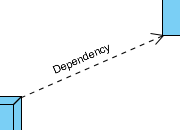
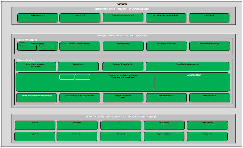
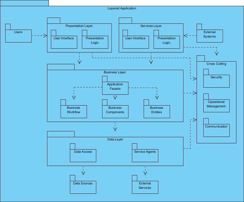
Dependency Diagrams Reference - Visual Studio (Windows ... A dependency diagram organizes the physical artifacts in your system into logical, abstract groups called layers. These layers describe major tasks that the artifacts perform or the major components of your system. Each layer can also contain nested layers that describe more detailed tasks. Dependency Diagrams: Guidelines - Visual Studio (Windows ... Like a traditional architecture diagram, a dependency diagram identifies the major components or functional units of the design and their interdependencies. Each node on the diagram, called a layer, represents a logical group of namespaces, projects, or other artifacts. You can draw the dependencies that should exist in your design. What Are Dependency Graphs and Why Are They Important ... Dependency graphs are powerful tools for managing complicated chains of calculations that make it easier to understand calculation flows, analyze dependencies, efficiently recalculate values after data changes, and drill into calculation problems. Excel is a dependency graph UML Dependency - Javatpoint In UML, a dependency relationship is the kind of relationship in which a client (one element) is dependent on the supplier (another element). It is used in class diagrams, component diagrams, deployment diagrams, and use-case diagrams, which indicates that a change to the supplier necessitates a change to the client. An example is given below:
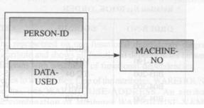
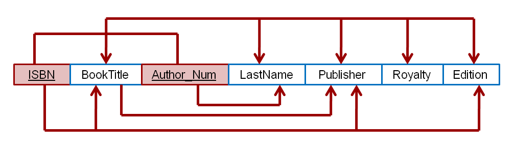
Dependency graph - Wikipedia In mathematics, computer science and digital electronics, a dependency graph is a directed graph representing dependencies of several objects towards each other. It is possible to derive an evaluation order or the absence of an evaluation order that respects the given dependencies from the dependency graph. Contents 1 Definition Dependency in UML - UML diagrams Dependency is a relationship between named elements , which in UML includes a lot of different elements, e.g. classes , interfaces , components , artifacts , packages, etc. There are several kinds of dependencies shown on the diagram below. Dependency relationship overview diagram - usage, abstraction, deployment. UML Notation Tutorial: UML Diagram Symbol with Examples Apr 16, 2022 · Behavioral diagram; Interaction diagram; Structural diagrams. Structural diagrams are used to represent a static view of a system. It represents a part of a system that makes up the structure of a system. A structural diagram shows various objects within the system. Following are the various structural diagrams in UML: Class diagram; Object diagram Functional Dependency Diagram and Examples | DBMS ... In a functional dependency diagram (FDD), functional dependency is represented by rectangles representing attributes and a heavy arrow showing dependency. Fig. shows A functional dependency diagram for the simplest functional dependency, that is, FD: Y -> X. In functional dependency diagram, each FD is displayed as a horizontalline.
Dependency Diagram Example - Diagram Media
Dependency Graph - an overview | ScienceDirect Topics The wiring diagram (also known as a dependency graph) of F is a directed graph with vertex set V = {x 1, …, x n}. A directed edge is drawn from x i to x j if, and only if, x i is present in at least one polynomial term (with a nonzero coefficient) of the local function f j.

Dependency Diagram Example - Diagram Media
Create dependency diagrams from your code - Visual Studio ... Apr 29, 2022 · 2. On the dependency diagram, open the shortcut menu for the layer, and then choose Paste. Create a new layer from an existing artifact link: Drag the artifact link to a blank area on the diagram. Verify that a linked artifact supports validation against the dependency diagram. Look at the Supports Validation column for the artifact link.
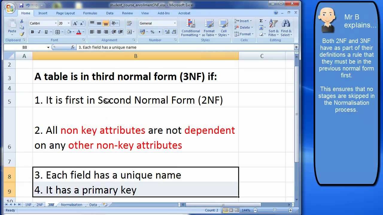
Normalisation 3NF: Understanding Third Normal Form - YouTube
What Is a Dependency in Gantt Charts? - Edraw - Edrawsoft What Is a Dependency in the Gantt Chart? Project management software use Gantt chart to visualize the information and dependency of tasks in project scheduling. Dependencies in the Gantt chart show the relationship between tasks in project management.
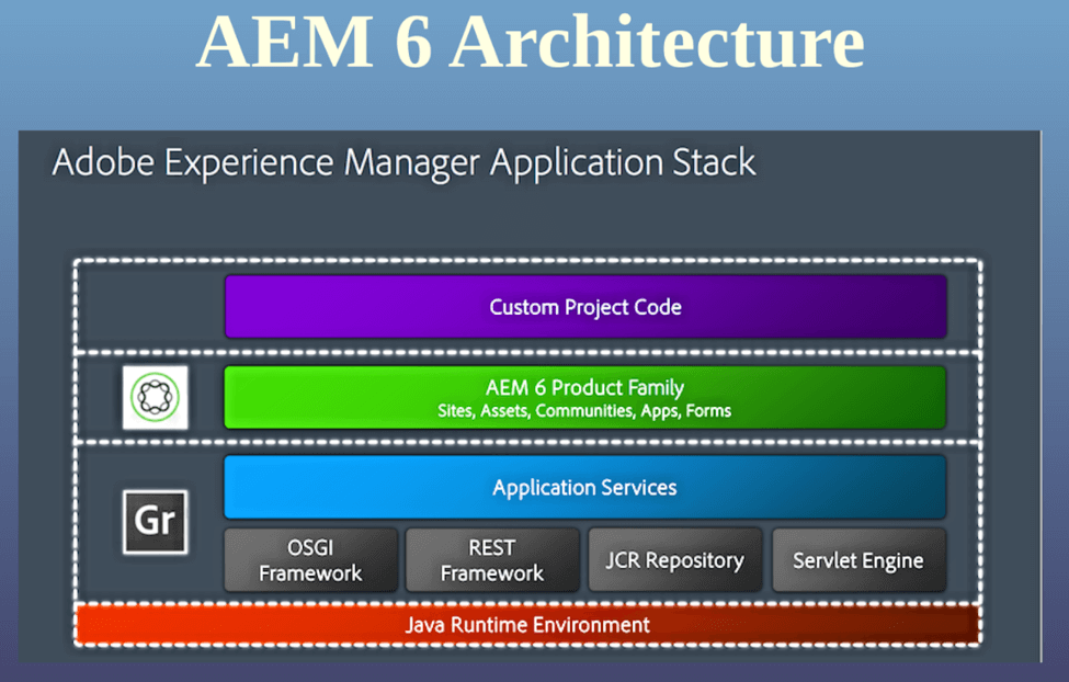
Test Automation for AEM Applications: A Primer - Infostretch
Pacing Guide and Dependency Diagram - KendallHunt Unit Dependency Diagram. In the unit dependency chart, an arrow indicates that a particular unit is designed for students who already know the material in a previous unit. Reversing the order would have a negative effect on mathematical or pedagogical coherence. The following chart shows unit dependencies across the 3-8 curriculum.
Project Dependency Diagram
dependencies - How is dependency in class diagram - Stack ... Dependency is easy, if a class can't live (i.e. compile or run) without another class then it has a dependency on the other class. So Algorithm has a dependency on Data, but Data has no dependency on Algorithm.
Deployment Diagram - UML 2 Diagrams - UML Modeling Tool
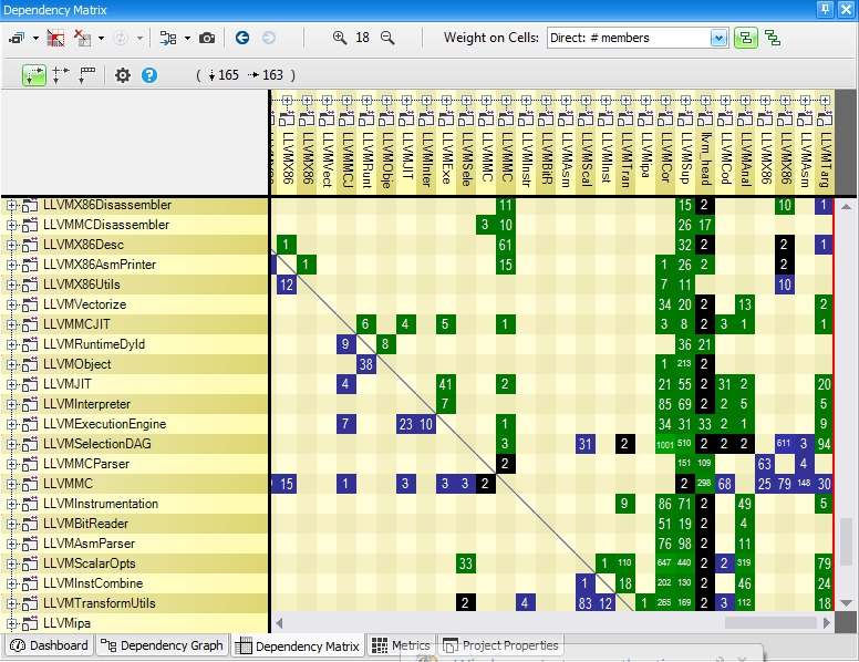
Project Dependency Diagram Thanks to the navigation bar, the project dependency diagram represents a great starting point to explore your code base. The Default Project Dependency Diagram : the Application Map By default the NDepend graph shows a graph named the Application Map.
How to Create a Process Landscape Diagram - Dragon1
How to create a SQL dependency diagram in SQL Server ApexSQL Analyze is a 3 rd party tool that can analyzes graphical SQL Server database object dependencies and the impact of potential deletions on your SQL database and create a SQL dependency diagram. It determines object interrelationships within the database, and allows customization of the resulting SQL dependency diagram appearance.

Overview of Spring Framework
Answered: What is a dependency diagram and what… | bartleby Draw the dependency diagram and identify the functional dependencies. Show the process of converting this table to 3NF. arrow_forward. A dependency diagram based on the table. arrow_forward. Using the descriptions of the attributes given in the figure, convert the ERD shown in Figure P6.2 into a dependency diagram that is in at least 3NF.
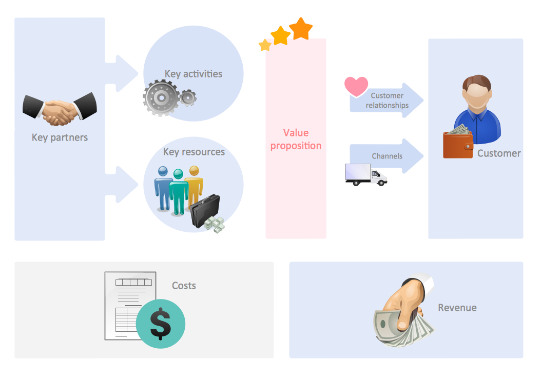
Business and Finance Illustrations Example
Pacing Guide and Dependency Diagram Dependency Diagram. In the unit dependency chart, an arrow indicates that a particular unit is designed for students who already know the material in a previous unit. Reversing the order would have a negative effect on mathematical or pedagogical coherence. The following chart shows unit dependencies across the 3-8 curriculum.

Dependency diagram, Draw the dependency diagram and recognize the primary key and all , Database ...
Using dependencies diagrams | monday.com Blog Dependencies diagrams are a visual way to present information. It can be much easier to understand how tasks hang together if they are presented in a way that clearly shows their sequencing rather than in a spreadsheet list. They can also show the same information, such as task duration, in a way that's much easier to read.
Dependency Graph
Dependency Walker (depends.exe) Home Page Dependency Walker is a free utility that scans any 32-bit or 64-bit Windows module (exe, dll, ocx, sys, etc.) and builds a hierarchical tree diagram of all dependent modules. For each module found, it lists all the functions that are exported by that module, and which of those functions are actually being called by other modules.

Draw the dependency diagram for the relation, Database Management System
Using Dependency Diagrams | Toolbox Tech Using Dependency Diagrams. Use a Dependency Diagram to show high-level dependencies among modules. It is not necessary to illustrate all time and data dependencies among modules. Some modules may be sufficiently unconnected in time or sequence and, therefore, are not shown on a Dependency Diagram. For example, a module may produce data that ...
35 Functional Dependency Diagram Example - Wiring Diagram List
Components on a Dependency Diagram (Illustrated) - Toolbox Optionality is represented on a Dependency Diagram with an open dot "o" for optional at either end of the line between two modules. The position of the "o" dot indicates the dependency between modules. The dot is near the module that always occurs. For example, assume there is a line joining Module X and Module Y.
The dependency diagram in shown below indicates that | Chegg.com
What is Package Diagram?
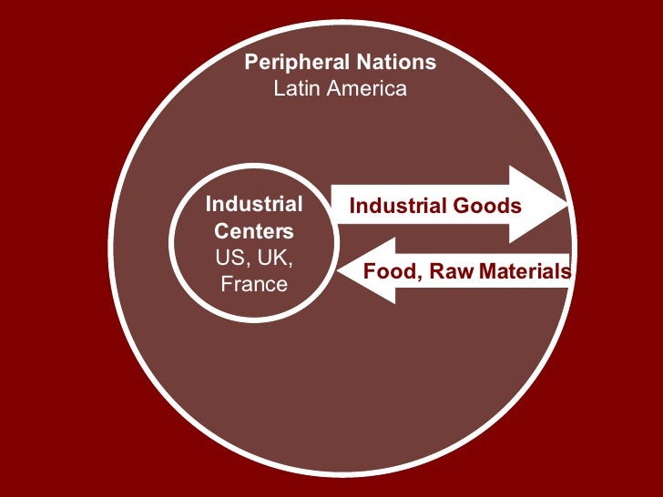
Inequity of Development in the Core and Periphery | by Gabby Turner | Medium

Model Dependency Diagrams.
0 Response to "45 what is a dependency diagram"
Post a Comment