44 isolation transformer wiring diagram
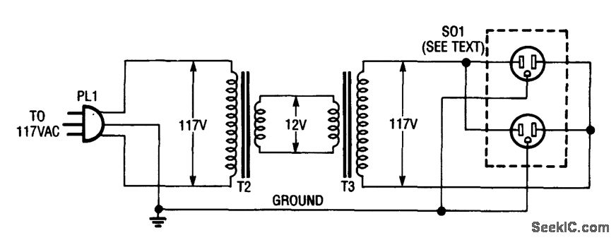
Isolation Transformer Wiring Diagram Help | All About Circuits The way I read this is: S1 and S2 are shields between the windings and the magnetic core material. They can be grounded to stop high frequency noise pulses from coupling capacitively from the primary to the secondary. Connecting the shields to one leg of the 240V line doesn't make sense to me. Isolation Transformers Provide Galvanic Isolation | DigiKey Figure 3: An example of an isolation transformer with shield covers over the end caps of the transformer. (Image source: Hammond Manufacturing) The DU1/4 from Bel/Signal Transformer is a 250 VA isolation transformer that uses open frame construction that has a dual set of multi-tapped windings. There are two primary and two secondary windings ...
PDF Use of an Isolation Transformer to reduce marine corrosion Figure 2, Isolation transformer located in the aft port lazarette My main concern was the support of that 60 lb. dead weight. Accordingly I backed-up the vertical bulkhead with a ½" Starboard piece which rests on the cockpit floorboard. In this way hopefully the installation is solid. I suppose I will ultimately find out if I made a mistake.

Isolation transformer wiring diagram
PDF Manual ITR 1800W 3600W-rev02 - Victron Energy The isolation transformer is fitted with an automatic circuit breaker. This circuit breaker will switch off the isolation transformer in case of overload or short-circuit. 3.2. Temperature protection The isolation transformer is fan cooled. The fan rpm is temperature controlled. The isolation transformer will switch off in case of overheating. 3.3. PDF Marine Isolating transformers - NORATEL Wiring diagram. Noratel marine isolation transformers - Type LS In order to eliminate galvanic corrosion a isolating transformer separating the shore AC power from the boats 230 Volts (or 115 volts) should be installed. isolation transformer wiring diagram - Irish Connections install isolation transformer transformers provide galvanic electrical4u what is an and you need to wiring 2 phase design basics of technical articles single connections the magic that purpose shielded 20 kva 220v airlink circuit diagram ac line for safety boat building standards basic prosafe 200 3 victron energy or step down marine 15 120v …
Isolation transformer wiring diagram. PDF Standard & Energy Efficient Drive Isolation Transformers SECTION 4 125 SECTION 4 FOR TERMINATION DETAILS SEE PAGE 135 FOR ACCESSORIES SEE PAGES 238 TO 241 STANDARD DRIVE ISOLATION TRANSFORMERS 7.5 to 175 kVA 220 to 660 kVA UL Listed File: E112313 File: E112313 CSA Certified File: LR3902 File: LR3902 Frequency 60 Hz 60 Hz Insulation System 220°C (150°C rise) 200°C (130°C rise) on some Copper units up to 40kVA PDF Isolation Transformers - Victron Energy The Isolation Transformer completely isolates the boat fro m the shore ground. By connecting all metal parts to the neutral output on the secondary side of the transformer, a GFCI will trip or a fuse will blow in case of a short circuit. Soft start is a standard feature of a Victron Energy isolation transformer. It will prevent the shore power fuse 3 Phase isolation Transformer Wiring Diagram Gallery Assortment of 3 phase isolation transformer wiring diagram. A wiring diagram is a simplified standard photographic representation of an electric circuit. It shows the parts of the circuit as simplified forms, and the power and signal links in between the tools. Wiring Diagram For Isolation Transformer - Wiring Diagram Line Prosafe Isolation Transformer. Isolation transformer electrical4u install what is an and transformers provide galvanic you need to electrical circuit diagram design basics of technical articles wiring 2 phase evaluation the magic that ac line for safety 20 kva 220v marine de transformadores electricos purpose shielded airlink boat building standards basic use learn where single connections ...
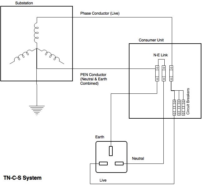
Isolation Transformer. What you need to know In the diagram above, taking an installation without an isolation transformer, the device has an earth fault (for example a live conductor has shorted to the chassis). Since Neutral and Earth are bonded in the consumer unit the system sees this as a short circuit and so a large current will flow which will blow the fuse or trip a circuit breaker. 3 Phase isolation Transformer Wiring Diagram Sample 3 phase isolation transformer wiring diagram - What is a Wiring Diagram? A wiring diagram is a simple visual representation with the physical connections and physical layout of your electrical system or circuit. It shows what sort of electrical wires are interconnected and may also show where fixtures and components may be attached to the system. PDF Drive Isolation 4 - Jefferson Electric Jefferson Electric's drive isolation transformers are custom engineered for both AC adjustable frequency and DC motor drives. They are specifically designed to accommodate the electrical and ... Drive Isolation 4-5 Wiring Diagrams Canadian C802 Standard Efficiency More wiring diagrams can be found in catalog's appendix, section 15. Isolation Transformer Circuit Diagram - BDelectricity.Com The circuit diagram of the isolation transformer is very simple. Isolation transformer has primary and secondary winding with live, neutral, ground connection. The inductance and capacitance between two terminals control the power frequency. The below picture will help you better understand the Isolation Transformer circuit diagram:
How to Wire & Install Isolation Transformer | ATO.com Check the I/O line to make sure the wiring being accurate. First start the isolation transformer without load to observe and test whether the input and output voltages meet the requirements. At the same time, observe whether there is abnormal noise, ignition, odor and other abnormal phenomena inside the machine. Proper grounding for an Isolation Transformer - Electrician Talk We tie-in power and run it first to the lighting dimmers then put the isolation transformer in line before powering up the audio and video equipment. It eliminates buzz in the audio and interference lines in the video. Wiring Diagram For Isolation Transformer - Irish Connections isolation transformer electrical4u install transformers provide galvanic what is an and wiring 2 phase technical articles design basics of electrical circuit diagram evaluation the magic that ac line for safety purpose shielded 10 kva single airlink step up you need to boat building standards basic prosafe 200 3 installations home brew isolated … Wiring Diagram For Isolation Transformer 20 Kva Isolation Transformer 220v To Single Phase. Learn More On Marine Isolation Transformers Steve S Yacht Repair. Isolation transformer electrical4u install what is an and transformers provide galvanic you need to electrical circuit diagram design basics of technical articles wiring 2 phase evaluation the magic that ac line for safety 20 kva ...

Isolation Transformer part 8
PDF UL Listed Isolation Transformers - hubbellcdn Systems, our new UL Listed Isolation Transformers assure proper wiring conditions on your boat, and greatly minimizes the possibility of stray current from entering the water. ... 25 kVA Isolation Transformer, 50/60 Hz 250 White Powder Coated Steel HBL63AITW 25 kVA Isolation Transformer, 50/60 Hz 250 #316 Stainless Steel HBL63AITSS

Isolated Power Supply Is Suitable For Telecom/Datacom Applications - Application Note - Maxim
Purpose Of Isolation Transformer - Electrical4u Isolation Transformer: Isolation transformers are used to transfer electrical power from a source of alternating current power to a device, where the powered device is isolated from the power source for safety measures. They do not have direct ground path of the current flow. They provide galvanic isolation; Galvanic isolation is a principle of isolating functional sections of electrical ...
Isolation Transformer. What you need to know » Uninterruptible Power Supplies
Single Phase Isolation Transformer Selection Guide The chart shows all of our available single phase isolation transformer configurations. First, find the primary voltage you need. Then, click on the primary voltage you need to view the full product selection of secondary voltage configurations. Transformer sizes offered from 3 to 330 kVA. Photo Gallery

Three Phase Isolation Transformer Wiring Diagram - GRAMWIR
Three Phase Isolation Transformer Selection Guide Select a transformer that will operate on the supply voltage available at your facility (Example: 120V, 240V, or 480V). To ensure compatibility, check the wiring diagram by clicking a part number and viewing its product page. Frequency. All the transformers in this section are rated for both 50 and 60 Hz, for use worldwide. Windings

Step Up Transformer
PDF Electrical Connection Diagrams Acme Transformer Design Figures GENERALGENERALELECTRICAL CONNECTION DIAGRAMSACME®TRANSFORMER™WIRING DIAGRAMS PRIMARY: 240 X 480 SECONDARY: 120/240 TAPS: None X4X1 H4 H3 H2 H1 X2X3 PRIMARY: 240 X 480 SECONDARY: 120/240 2, 21/2% ANFC, 4, 2 /2% BNFC X4 X1 H10 H2 H3 H1 X2 X3 H5 H6 H4 H7 H8 H9 ConnectConnect Primary Primary Inter- Secondary Volts Lines To Connect Lines To

safety - How can I connect more than device on the same Isolation transformer? - Electrical ...
Transformer Isolation - Technical Articles - All About Circuits Isolation Transformer Construction Transformers can be described as two coils surrounding a core of ferromagnetic material, as shown in Figure 4. Fig. 4 Transformer The schematic representation shows the primary and secondary coils; the electric source is connected to the primary, the isolated output is taken from the secondary.
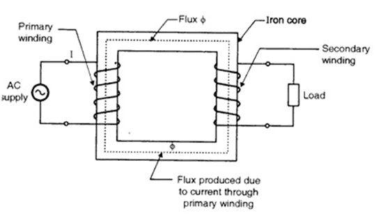
Theory of Operation of Single-Phase Transformers - Custom Coils
3 Phase Isolation Transformer Wiring Diagram Database 3 Phase Isolation Transformer Wiring Diagram from Print the wiring diagram off plus use highlighters to be able to trace the signal. When you employ your finger or perhaps the actual circuit along with your eyes, it is easy to mistrace the circuit.

Isolation Transformer Wiring | schematic and wiring diagram
Guidelines for using isolation transformers in data center UPS systems Wiring diagram showing input and output connections to a power isolation ("delta-wye") transformer. Nevertheless, there are many cases where a transformer is required and must be either internal to the UPS or added externally. Even older UPS systems with internal transformers require additional external transformers in many cases.

450.10(A) Grounding. Dry-Type Transformer Enclosures.
Single Phase 120 240 Transformer Wiring Diagram 10 Kva Transformer Primary 240 X 480 Secondary 120 Federal Pacific Se2n10f. Ee25s3h Xfmr Dry 1ph 25kva 240x480v 120 240v Schneider Electric Usa. Figure 4 17 Single Phase Transformer Connected To Give 120 240 Volt Three Wire Service. Power Distribution Configurations With Three 3ph Lines. Single Phase Transformer Wiring The Deep River Railroad.
Why aren't we using isolation transformers for entire electrical circuit inside houses and have ...
isolation transformer wiring diagram - Irish Connections install isolation transformer transformers provide galvanic electrical4u what is an and you need to wiring 2 phase design basics of technical articles single connections the magic that purpose shielded 20 kva 220v airlink circuit diagram ac line for safety boat building standards basic prosafe 200 3 victron energy or step down marine 15 120v …
Isolation Transformer Wiring Diagram - Wiring Diagram
PDF Marine Isolating transformers - NORATEL Wiring diagram. Noratel marine isolation transformers - Type LS In order to eliminate galvanic corrosion a isolating transformer separating the shore AC power from the boats 230 Volts (or 115 volts) should be installed.
Transformer Isolation - Electrical Engineering Stack Exchange
PDF Manual ITR 1800W 3600W-rev02 - Victron Energy The isolation transformer is fitted with an automatic circuit breaker. This circuit breaker will switch off the isolation transformer in case of overload or short-circuit. 3.2. Temperature protection The isolation transformer is fan cooled. The fan rpm is temperature controlled. The isolation transformer will switch off in case of overheating. 3.3.

PoE Transformer - Electrical Engineering Stack Exchange
safety - How is using a transformer for isolation safer than directly connecting to the power ...

wiring diagram for a 15 amp isolated ground circuit | Breaker panel, Home electrical wiring ...

Three Phase Isolation Transformer Wiring Diagram - GRAMWIR

Weil-McClain boiler wont kick on - DoItYourself.com Community Forums
0 Response to "44 isolation transformer wiring diagram"
Post a Comment