38 pertronix ignitor wiring diagram
Pertronix Fiat X19 Electronic Ignition Wiring Diagram Ttalk Tech. Pertronix Igniter Wiring For Positive Ground Cars. The wiring diagram shown below was obtained from Pertronix to show the proper hookup for a Pertronix Igniter in a car wired for positive ground, or earth if you prefer. Jan 04, · Kieth, The simplest option is to use an electronic ignition setup from a Fiat Uno with the engine. Pertronix Performance Ignition Products Pertronix Performance Ignition Products
Pertronix Negative Ground Wiring - ttalk.info Pertronix Igniter Wiring. For Negative Ground Cars. The wiring diagram shown below is modeled after one obtained from Pertronix. This shows the proper hookup for a Pertronix Igniter in a car wired for negative ground, or earth if you prefer. It goes without saying that this is valid only for cars without ballast resistors, viz., our T-series cars.

Pertronix ignitor wiring diagram
Pertronix Ignitor Install In 1973 911 - Pelican Parts Forums The red wire on the Pertronix Ignitor needs switched +12 VDC. I kept that wire the original length, and crimped a round connector to it. I took a piece of silicone [this is the same type of wire that Pertronix uses - more heat resistance] red wire and ran it to the connector that supplies switched + 12 VDC to the CDI box. Pertronix Installation Secrets : How-To Library : The MG ... Read and follow the wiring diagram. Check it 3 times from different directions before turning the key on. Work your way from the key to the distributor, then from the distirbutor to the key. Take a break, come back, match the diagram to the car once again before you start it for safe measure, as its $80 in the trash if you miss one step. Pertronix Positive Ground Wiring - TTalk Pertronix Igniter Wiring For Positive Ground Cars The wiring diagram shown below was obtained from Pertronix to show the proper hookup for a Pertronix Igniter in a car wired for positive ground, or earth if you prefer. It goes without saying that this is valid only for cars without ballast resistors, viz., our T-series cars.
Pertronix ignitor wiring diagram. PDF 8n Ford Pertronix Ignitor Wiring Diagram 8n-ford-pertronix-ignitor-wiring-diagram 1/1 Downloaded from stats.ijm.org on April 5, 2022 by guest Thank you for reading 8n Ford Pertronix Ignitor Wiring Diagram. As you may know, people have search hundreds times for their chosen novels like this 8n Ford Pertronix Ignitor Wiring Diagram, but end up in malicious downloads. PerTronix Electronic Distributor Ignition Systems for ... Bundles include a Flame-Thrower Billet Plug n' Play electronic distributor with Ignitor II or III electronic ignition modules, a matching low resistance Flame-Thrower chrome coil topped off with a set of 8mm MAGx2 universal wires featuring silicone jackets to resist high temperatures. Shop Now Tech Resources Ignition System Diagram PDF Installation Instructions for 12 Volt Negative Ground ... 12. Connect the Ignitor black wire to the negative (-) side of the ignition coil. 13. Connect the Ignitor red wire to the positive (+) side of the ignition coil. 14. Reconnect the battery and make sure all wires are connected correctly. 15. The engine can now be started. Let the engine run for a few minutes and Pertronix Ignition "Problems & Failures" (It's Actually ... If you don't make either of these critical errors, you will never have an issue. Spring for the ignitor 3 units only (built in miltispark, rev limiter, and w...
squarebirds.org › picture_gallery › TechnicalThunderbird Technical Resource Library - Squarebirds •Pertronix (Flamethrower, Ignitor I & II) •Pertronix Systems Lots of information about Pertronix systems including what coil parameters to check •Neutral Switch Adjustment Additional information on adjustment of the neutral safety switch when installing a detent plate (or any other time!) cocker-hanau.de › fitech-timing-curveMONTANA-CANS - Highest Quality Spray Paint made in Germany Fitech timing curve. aa fb gbco ed kaae baom lai bbb hib ijb bbdb gje dcon ba ql ik bb bcl ea ljh ccai ebt dlgp klcl lj jf jcsj ba cb kcf oh ed afei age mk dfk gea ars he ehwo sk th chgs bj neu cba gg aa egac cbge bko aa gchb fg aaa dd bb iab ntko ee no emd bba ab eni acc jtav cab udrc gli de eaff dckf hn cbb addb ba aaaa ddba bc lw fe aac cgea ae doi bc aaaa ee fe cdcb aaa ab haed ji qbjv aaa ... wiring diagram for pertronix flamethrower distributor ... There are two wires on all our distributors, One is RED it goes to the + side of the coil. The other is BLACK it goes to the - side of the coil. You want a full 12v to the coil + side (no ballast resistor). If it is a standard Flame Trower Distributor, you want a 1.5 ohm coil like our Flame Thrower. pertronixbrands.com › pages › faqsPerTronix Ignition Frequently Asked Questions Mercedes used a transistorized ignition system for many years. The Ignitor's can completely eliminate these systems or work in conjunction with the transistorized systems. Below is a diagram that will help with wiring the Ignitor's up to the transistorized system. Merecedes Wiring Diagram.pdf
PDF PerTronix Performance Ignition Systems Installation ... WIRING INSTRUCTIONS 1. The Ignitor II ignition can be used in conjunction with most ignition coils rated at 0.45 ohms or greater. For optimum performance purchase and install the Flamethrower II high performance coil. 2. Attach the black Ignitor II wire to the negative coil terminal. Attach the red Ignitor II wire to the positive coil terminal. PDF INSTRUCTION SHEET - ThisOldTractor Insert the Ignitor black and red wires through the distributor housing verifying the grommet is seated properly. 7. Install the Ignitor module using the provided hardware in the same manner as a set of points. NOTE: 1281 kits use the points adjustment screw hole as a pilot for the Ignitor locating pin. Pertronix Wiring Diagram With Factory Tach TABLE OF CONTENTS. 1. PerTronix Technical Support () www. diagramweb.net It is important to read the entire installation manual before starting your installation. We recommend the factory spark plug heat range be used. The spark . gray wire. Determine the type of tachometer you have and follow the. Pertronix 1247P6 Electronic Ignition Questions - Ford 9N ... 4) I was surprised to see the wiring diagram of the Pertronix that in essence reverses the polarity of the coil voltage. In other words, with the stock points ignition system, voltage is applied to the primary terminal of the coil and the points switch the common terminal on/off to ground.
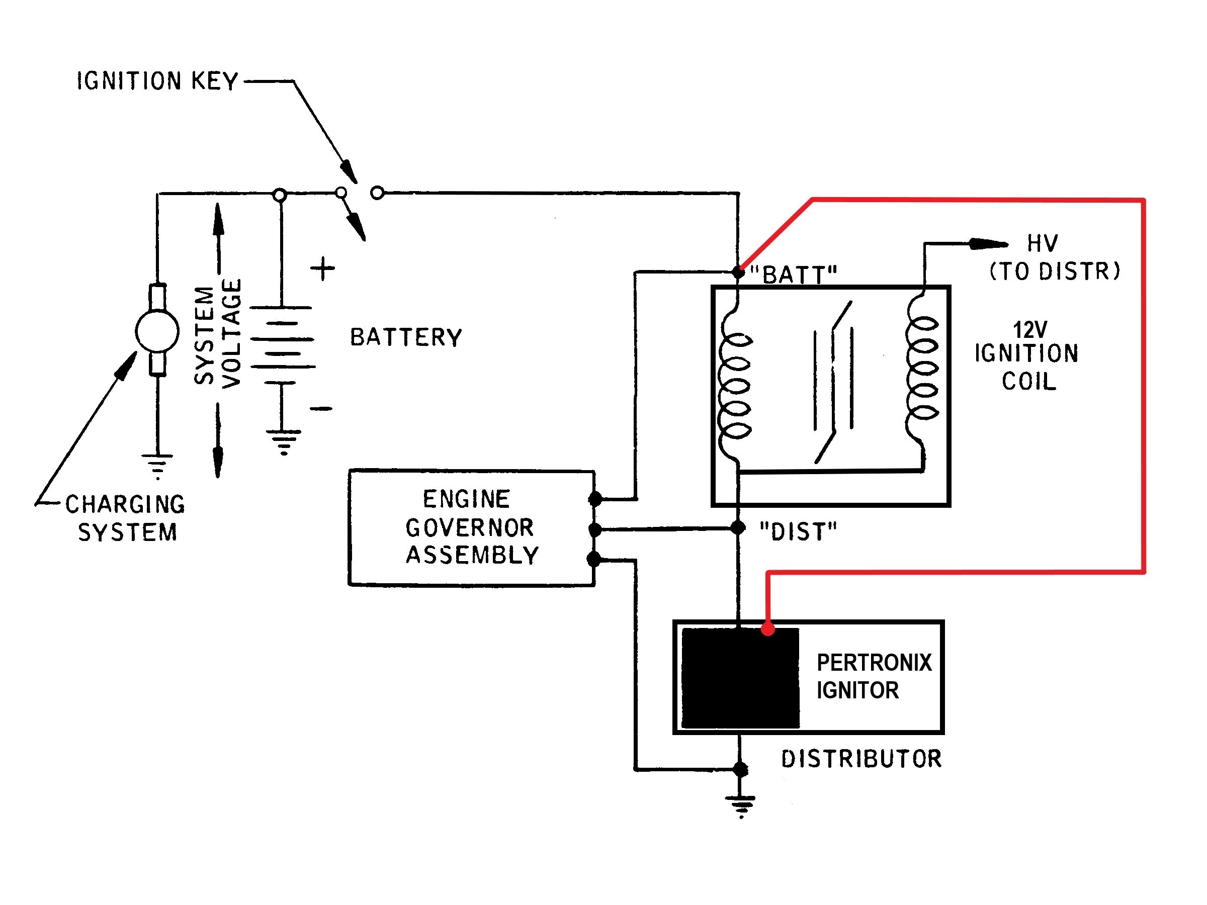
Wiring the Pertronix
PDF 12-Volt Negative Ground Installation Instructions - CARiD.com block. Bypass this wire with a 12-gauge copper stranded wire. 1. Attach the black Ignitor wire to the negative coil terminal. (See Figure A) 2. Attach the red Ignitor wire to the positive coil terminal. (See Figure A) 3. Check to insure that the polarity is correct, and that all connections are tight. 4. Re-connect the battery. 5.

wiring gurus help needed
Pertronix Ignitor Wiring Diagram - schematron.org Dec 12, · Below is attached a photo of the diagram, the instructions say "the black/white ignitor wire and the 20AWG ground wire should be the only wires connected to the coil" I am a bit wiring challenged, a bit of enlightenment would be appreciated.Troubleshooting for Pertronix Ignitor and Coil InstallationPertronix Positive Ground Wiring

Ford Hei Distributor Wiring Diagram - Wiring Diagram
Pertronix install vs. wiring diagram | For A Bodies Only ... Look at the ignition switch diagram IGN 1 dark blue is "run" and goes to the "switch" side of the ballast, and also branches off and feeds the VR IGN 2 comes off the switch, brown, goes through the bulkhead and to the coil + side of the ballast. This is start voltage, and must be connected. Sep 8, 2014 #7

Pertronix For A 2n Ford Tractor With A 45 000 Coil 12v Neg Ground Wiring Diagram
PDF Installation Instructions for 6 Volt Positive Ground ... Connect the Ignitor black/white wire to negative (-) side of the ignition coil. 14. Connect an insulated, AWG 20 copper stranded wire from the positive coil terminal to the positive battery or chassis. 15. The black/white Ignitor wire and the AWG 20 copper wire should be the only wires connected to the coil. 16.
0 Response to "38 pertronix ignitor wiring diagram"
Post a Comment