39 coolant temperature sensor wiring diagram
anybody have a diagram for which wires go to where for the coolant temp sensor on the bottom of the coolant neck? the wires all broke on mine, and the car.13 answers · 0 votes: I had a bad cts and I ended up just grounding the wires onto the thermostat housing and it ... temperature. Then, the thermostat opens, allowing coolant to flow from the engine to the radiator. Ford F 250 Oem Parts Diagram | Reviewmotors.co 3sz ve engine diagram [email protected] Engine, user manuals, operating Jun 05, 2019 · Ve Commodore Wiring Diagram - wiring diagram is a
Read PDF Nissan Service And Maintenance Guide 2005 drive Clutch and external shift mechanism Transmission and internal shift mechanism Engine management system Electrical system Wheels, tires and drive train Front suspension and steering Rear suspension Brakes Body and Color wiring diagrams. "pertaining to schemes," 1701, from Latin stem of scheme (n.) + -ic.
Coolant temperature sensor wiring diagram
Spal Electric Fan Replacement Sending Units. Spal electric fan replacement electronic sending units are designed for use with their temperature control modules. They are manufactured from high-quality materials and help you control your fan. Restore your electric fan operation with Spal replacement sending units. 2000 Dodge Ram 1500 Oxygen Sensor Locations Januari 08, 2022 Dapatkan link; Facebook; Twitter The other is the rewiring of the stockengine wiring harness to accommodate the Autronic, which will come underthe category of Rewiring. You can click on any of the smaller imageson this page to view them larger. ... They are as follows, the Air Flow Meter,the Turbo Pressure Sensor (MAP), the Injector Resistor Pack, the Fuel PumpResistor, the ...
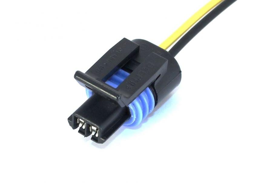
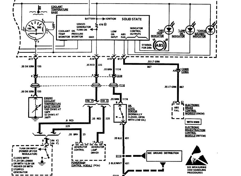
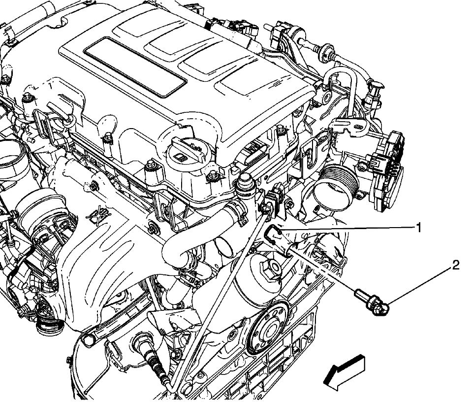
Coolant temperature sensor wiring diagram. If the wiring does not work as indicated in Step 4 third bullet, Check for an open in the yellow signal wire or a disconnected or corroded ECT sensor connector, see Figure 1 or the downloaded wiring diagram. Testing Engine Coolant Temperature Sensor Check that radiator reservoir bottle is full and radiator itself is filled to top. Koso North America. KOSO, a synonym for quality and performance has been operating for more than 30 years . Designing and manufacturing high-quality products, KOSO is well known in the motorcycle, snowmobile, ATV and scooter industries. KOSO's good reputation for reliability and innovation capability helped make KOSO a source for many major ... Dakota Digital MCL Series Speedometer So before we cut, spliced, and soldered, we downloaded the OEM wiring diagram for this. Diagram to determine wire color and location. This system can cause your odometer mileage to increase very rapidly if the speedometer is reading too fast.The oil sending unit, temperature sending unit, and speedometer. 2002 ford focus cooling system diagram. 2002 Ford Focus 2.0L SFI: I have a 2002 Ford Focus 2.0L SFI, I have a 2002 Ford Focus 2.0L SFI, none of the 2 radiator cooling fans are coming on not even when I get the A/C on I've check there's no went into live data to check the coolant temperature sensor an … Engine Cooling.
Since November 1st, I have changed the battery, negative cable, starter motor, ignition coil, coolant temperature sensor, spark plugs, wires, and other components. As of February 14th, it was running good. But when I went to a friend's and began to leave, it was backfiring and wouldn't start. Advice? December 31, 2021 · Wiring Diagram. by Hadir. 110V Plug Wiring Diagram - 110v ac plug wiring diagram, 110v male plug wiring diagram, 110v plug wiring diagram, Every electrical arrangement consists of various different components. Each component ought to be set and connected with other parts in particular manner. The hole dead-centre of the photo is where the TMAP sensor mounts. It's held in place, obviously, by the 2 screws either side of the hole. Not an easy place to get to, being tucked up under the throttle body when the BBM is bolted on. This is the AU1 wiring plug, which like the sensor, is unique to the AU1. Controlbyweb Temperature Sensor For Products. 9 2 Coolant Temperature. Single Ds18b20 Temperature Sensor Wiring Diagram 14core Com. Wiring Diagram Of The Multi Sensor Monitoring System Main Scientific. 1993 1995 Iat And Ect Sensor Wiring Diagram Jeep 4 0l. Help Wiring Up Temp Sensor And 2 Leads On Bmv 712 Victron Community.
Stewart Warner Deluxe Series Gauges. Gauge, Deluxe Series, Water Temperature, 100-280 Degrees F, 2 1/16 in., Analog, Electrical, Black Face, Each throttle body, cam sensor, injector harness, ecu temperature sensor, cluster temperature sensor, p/s pump, oil pressure sending unit, and ac compressor. Upper and lower NB radiator hoses will be needed (we recommend new). For best results in adapting an NB engine into a 90-93 we recommend using …05/11/2021 · The sensor wiring to the 12 Jan 2018 — But with the wire color discrepencies, I'm not sure the schematic is right... and I don't want to hook it up wrong and fry something else... Hyundai Tucson Engine Coolant Temperature Sensor Ects Schematic Diagrams Control System. 1 2 3 wire coolant temperature engine sensor how gm 12146312 interface digifizmini 9 diy ects ect wiring diagram the owner of vw passat audi a4 1990 2000 iat and micro introduction circuit pin for 2gr mr2 learn intake air p0118 dodge ram truck 1500 2500 3500 manual atw sensors techdoc m44 temp colors gsic ...
Chevy Engine Cooling Diagram - 88 Wiring Diagram
E39 Auxiliary Fan Wiring Diagram - wiring diagram is a simplified up to standard pictorial representation of an electrical circuit. It shows the components of the circuit as simplified shapes, and the aptitude and signal friends together with the devices. A wiring diagram usually gives counsel very nearly the relative position and settlement ...

Closeup of skeleton pelvic model
Nov 18, 2020 - Ls1 Engine Wiring Diagram and Ls Engine Controls ... Wiring Diagram For Code 33 - MAP Sensor Circuit (Signal Voltage High - Low Vacuum).
Corvette Coolant Temperature Sensor Wiring Harness, 1985-1995
Thor Rv Wiring Diagram - Complete Wiring Schemas Chevy Blazer 1995-2005 Fuse Box Location and Diagram; Chevy Cobalt 2004-2010 Fuse Box Diagram; Chevy Impala 2000-2005 Fuse Box Diagram; Chevy Malibu 1997-2005 Fuse Diagram; The under-hood fuse block in the engine compartment on the driver's side of the vehicle near the battery.
32 Engine Coolant Temperature Sensor Circuit Diagram ...
A bad manifold absolute pressure (MAP) sensor can upset fuel delivery and ignition timing. Depending on your vehicle model, your engine might experience one or more of these performance problems: Rich air-fuel ratio. Lean air-fuel ratio. Surging. Poor fuel economy. It won't start. Lack of engine power.

Honda Accord Cooling System Diagram - Wiring Forums
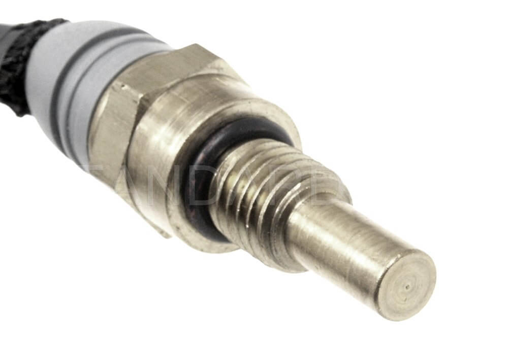
Coolant Temperature Sensor Wiring Diagram. 02:30 Minutes Read. The engine coolant temperature (ECT) sensor is a resistor-based sensor, which measures the ...

Autotronics Studies: Input Sensors and Actuators On - Vehicle
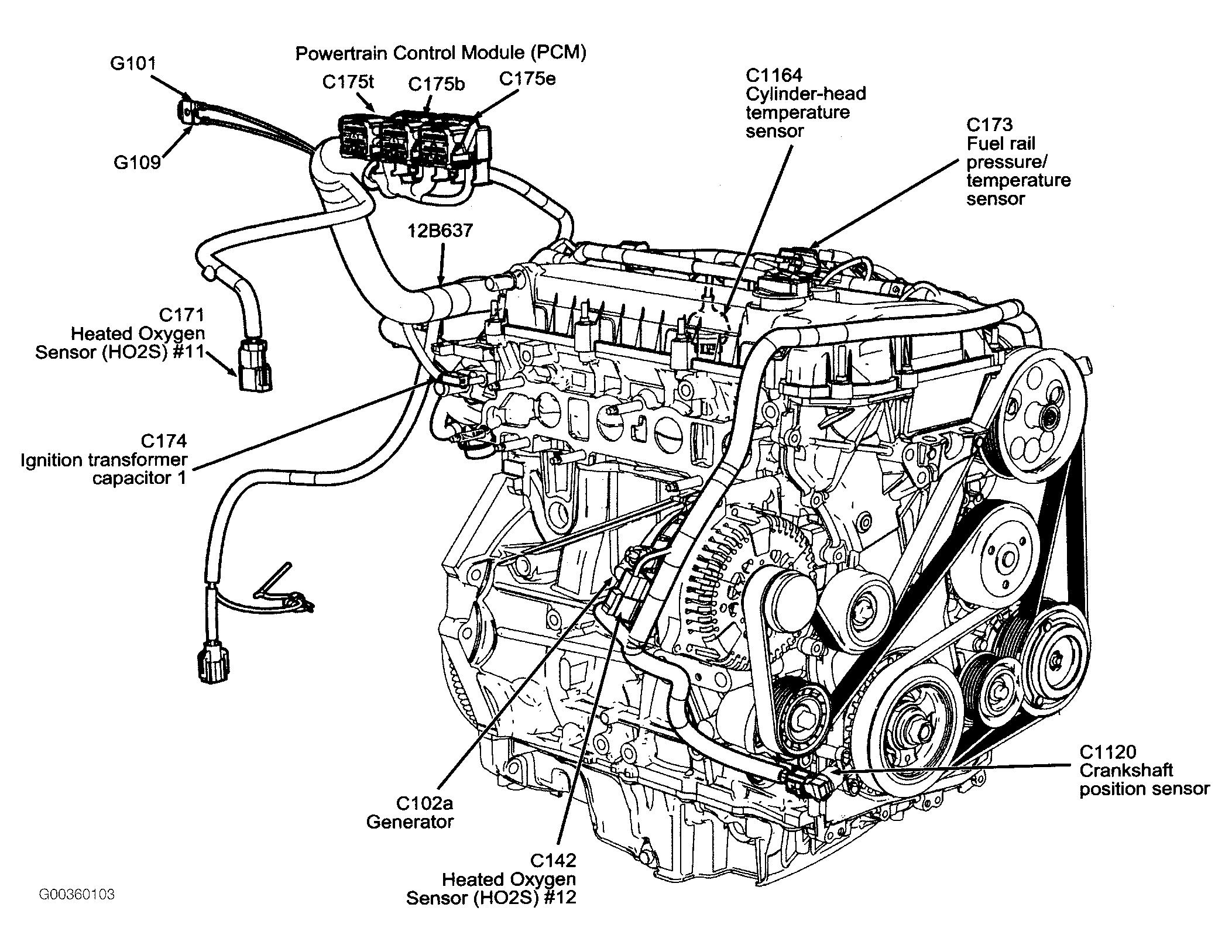
The coolant temp sensor for the pcm has two wires and is located near the thermostat. Get the engine surface temperature using an infrared thermometer or suitable cooking thermometer. Find your coolant temperature sensor wiring diagram here for coolant temperature sensor wiring diagram and you can print out. Search for coolant temperature ...
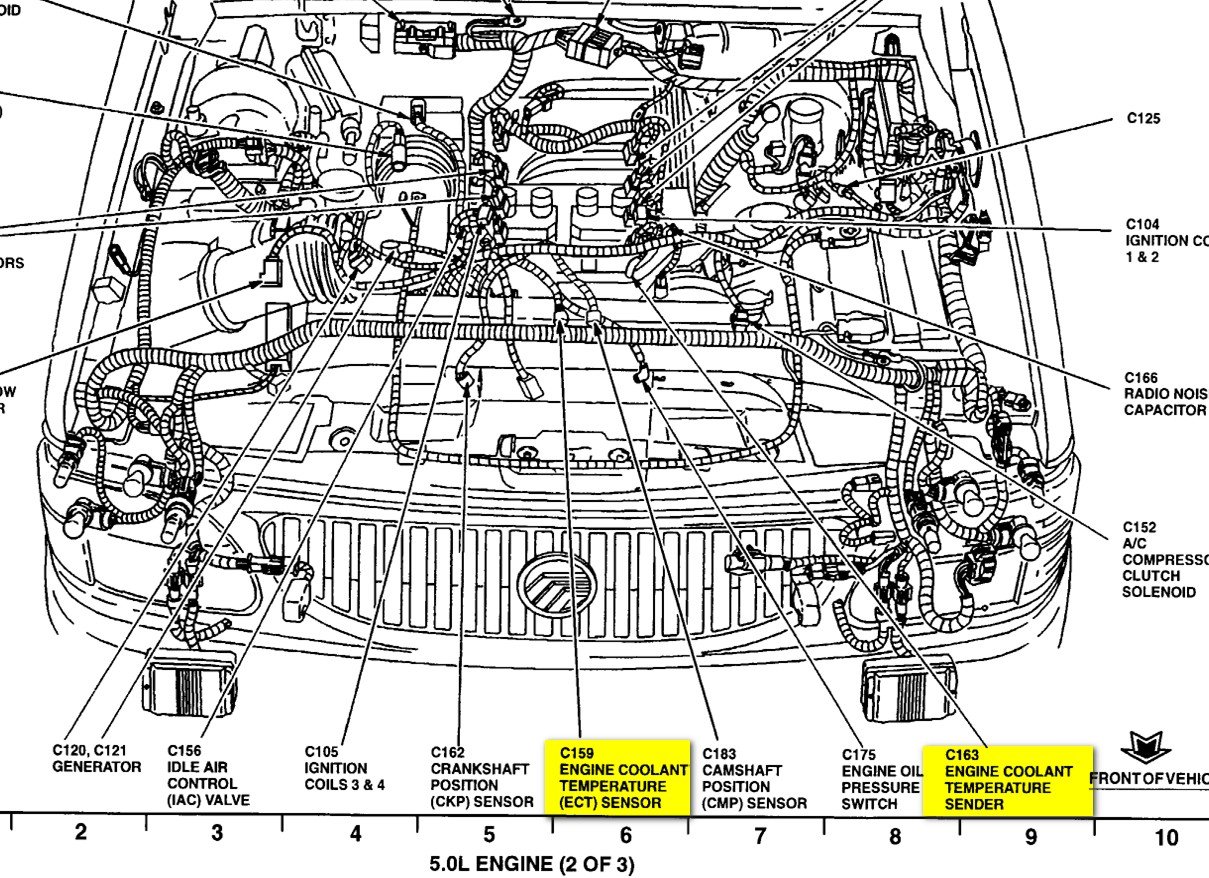
2005 Mercury Mountaineer Coolant Temperature Gauge Wiring ...
17 Aug 2019 — I Was Told That Was My Problem. Asked by Bill Cook2 ·. 3 ANSWERS. 1 IMAGE. 2006. HYUNDAI ELANTRA. Coolant Temperature ...
Temperature Sensor Diagram: Hi, Does Anyone Know the ...
A12 (central relay and fuse box) b11 (coolant temperature sensor) b17 / 9 (charge air temperature sensor) b19 (catalyst temperature sensor) b19 / 12 (temperature sensor in front of the particulate filter) b19 / 12×1 (electrical plug connection of the temperature sensor in front of the particulate.

Where is the coolant temperature sensor located on a 1994 ...
Ford Technical Documents - Ford Modifications Website. Ford EBII - ED Inline 6 EEC-IV Wiring Information: This document describes the pinouts, and wiring for the EEC-IV Engine and Powertrain Control Module, for the EL 6 cylinder FORD FALCON EBII & ED 4.0L 1993-94, FORD FAIRLANE NC & NCII, LTD DC & DCII 1993-94, XG Utility and Van 1993-96 Model Falcons
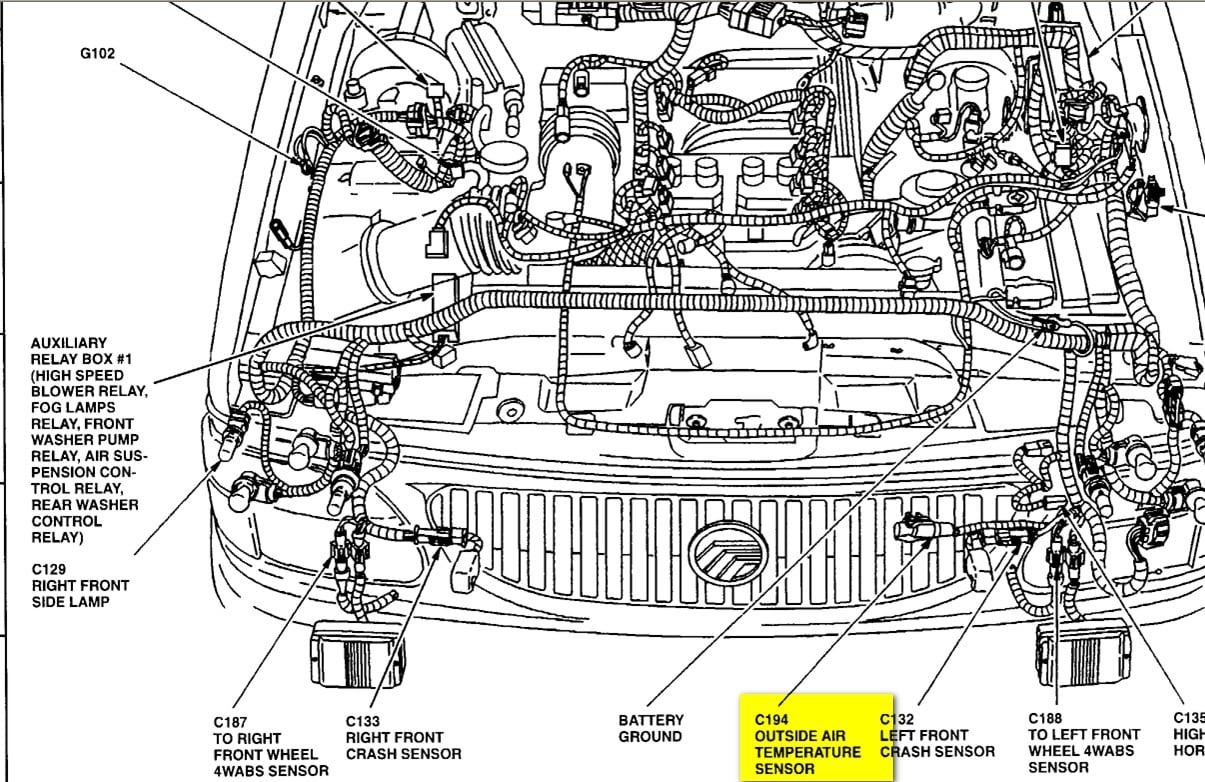
2005 Mercury Mountaineer Coolant Temperature Gauge Wiring ...
It was located close to the two-wire one on the PS of the engine. I THINK I remember it looked like a conventional automotive oil pressure sensor with only one wire. #2--I don't remember where the coolant temperature sensor was located, but I think it was in the vicinity of the thermostats, near the rear of the engine.
31 Coolant Temperature Sensor Wiring Diagram - Wiring ...
as possible are, but not limited to: air flow, coolant …AUTEX 1PC ABS Wheel Speed Sensor Connector N15002 10340314 970040 Wheel Speed Sensor Wire Harness Repair Kit Compatible with Century 05-01, DeVille/Impala 05-00, Grand Prix 08-00, LaCrosse 09-05 4.6 out of 5 stars 89MAV_MODE [Enum] These defines are predefined OR-combined mode flags ...

Where is the temperature sending unit on a 1999 VW - Fixya
Coolant Temp Sensor Wiring Diagram Integra. By Margaret Byrd | December 9, 2021. 0 Comment. How to remove the radiator fan switch coolant temperature connector team integra forums new t stat ect sensor temp gauge still stays in cold 95 of time honda tech forum discussion 92 00 acura engine wiring guide b18b broken eg dc2 conversion harness k manualzz dtc p0118 replace check an what model ...
9.2. Coolant Temperature
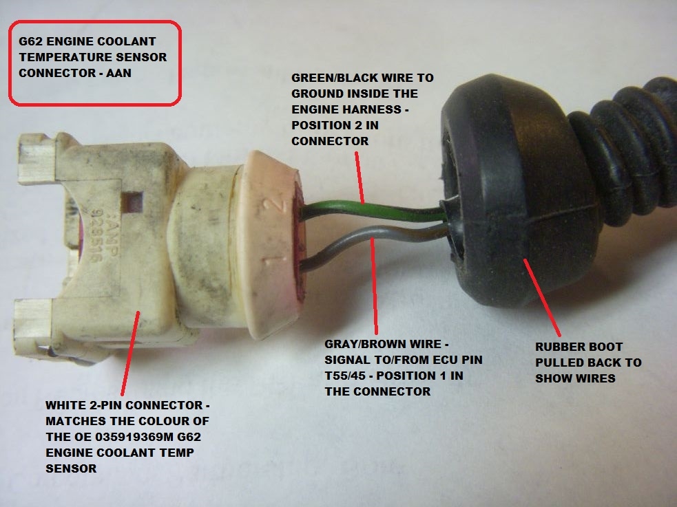
The coolant Temp Sensor has two units in one (G62 & G2) G62 is connected to the ECU via Brown/Green wire (at T121/104 at ECU) and Blue/Brown wire (at T121/112 at ECU). G2 is connected to the Temp Gauge in the Cluster via a Lilac wire. The other wire, Brown/White, goes to a common "splice" labeled as #269.

The location of the engine coolant temperature sensor on ...
The other is the rewiring of the stockengine wiring harness to accommodate the Autronic, which will come underthe category of Rewiring. You can click on any of the smaller imageson this page to view them larger. ... They are as follows, the Air Flow Meter,the Turbo Pressure Sensor (MAP), the Injector Resistor Pack, the Fuel PumpResistor, the ...
Coolant Temperature Sensor Location: I Am Trying to Locate ...
2000 Dodge Ram 1500 Oxygen Sensor Locations Januari 08, 2022 Dapatkan link; Facebook; Twitter
How do I configure temperature sensor in 5efe engine ...
Spal Electric Fan Replacement Sending Units. Spal electric fan replacement electronic sending units are designed for use with their temperature control modules. They are manufactured from high-quality materials and help you control your fan. Restore your electric fan operation with Spal replacement sending units.

Closeup of skeleton hand model

2005 Chevy Uplander Starter Wiring Diagram Fantastic ...

Coolant Temperature Sensor Wiring Diagram - Atkinsjewelry

Dd15 Coolant Temperature Sensor Location | Wiring Diagram ...

Coolant Temperature Sensor Wiring Diagram - General Wiring ...

Toyota Sequoia Limited - Toyota Sequoia 2004 Repair

| Repair Guides | Sending Units | Coolant Temperature ...

Wiring Diagram Database: Ls1 Coolant Temp Sensor Wiring ...
Coolant Temperature Sensor Location and Diagrams: We Are ...

How do you connect the wiring for a performance chip on ...

| Repair Guides | Electronic Engine Controls | Engine ...
quattroworld.com Forums: G62 Engine Coolant Temp (ECT ...

| Repair Guides | Sending Units And Sensors | Coolant ...
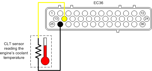
Two-Wire Temperature Sensor Circuit Diagram

| Repair Guides | Coolant Temperature Sensor | Testing ...
Coolant Temperature Sensor Location: Anyone Have a Diagram ...

Closeup of skeleton pelvic model

2000 F350 7 3 Coolant Temp Sensor Wiring Diagram ...

00 Ford F 150 Coolant Temp Sensor Location - Wiring Forums

Repair Guides
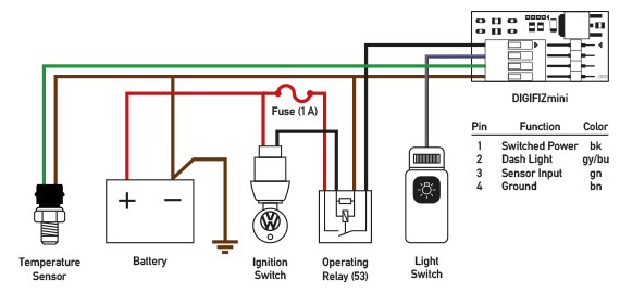
DIGIFIZmini
Ls1 Coolant Temp Sensor Wiring Diagram - Ekerekizul

| Repair Guides | Electronic Engine Controls | Engine ...
0 Response to "39 coolant temperature sensor wiring diagram"
Post a Comment