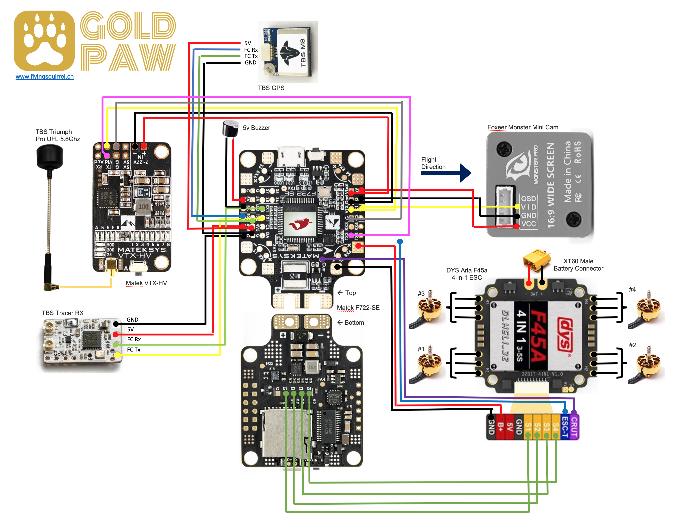
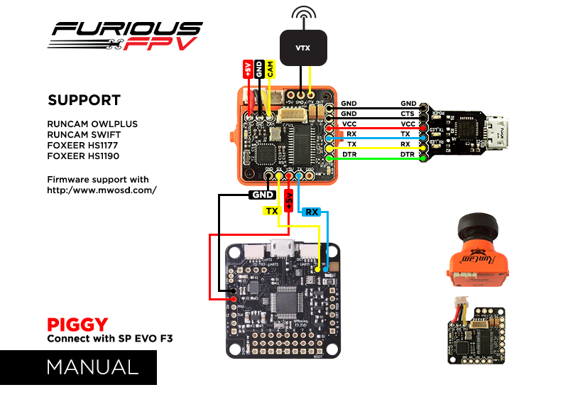
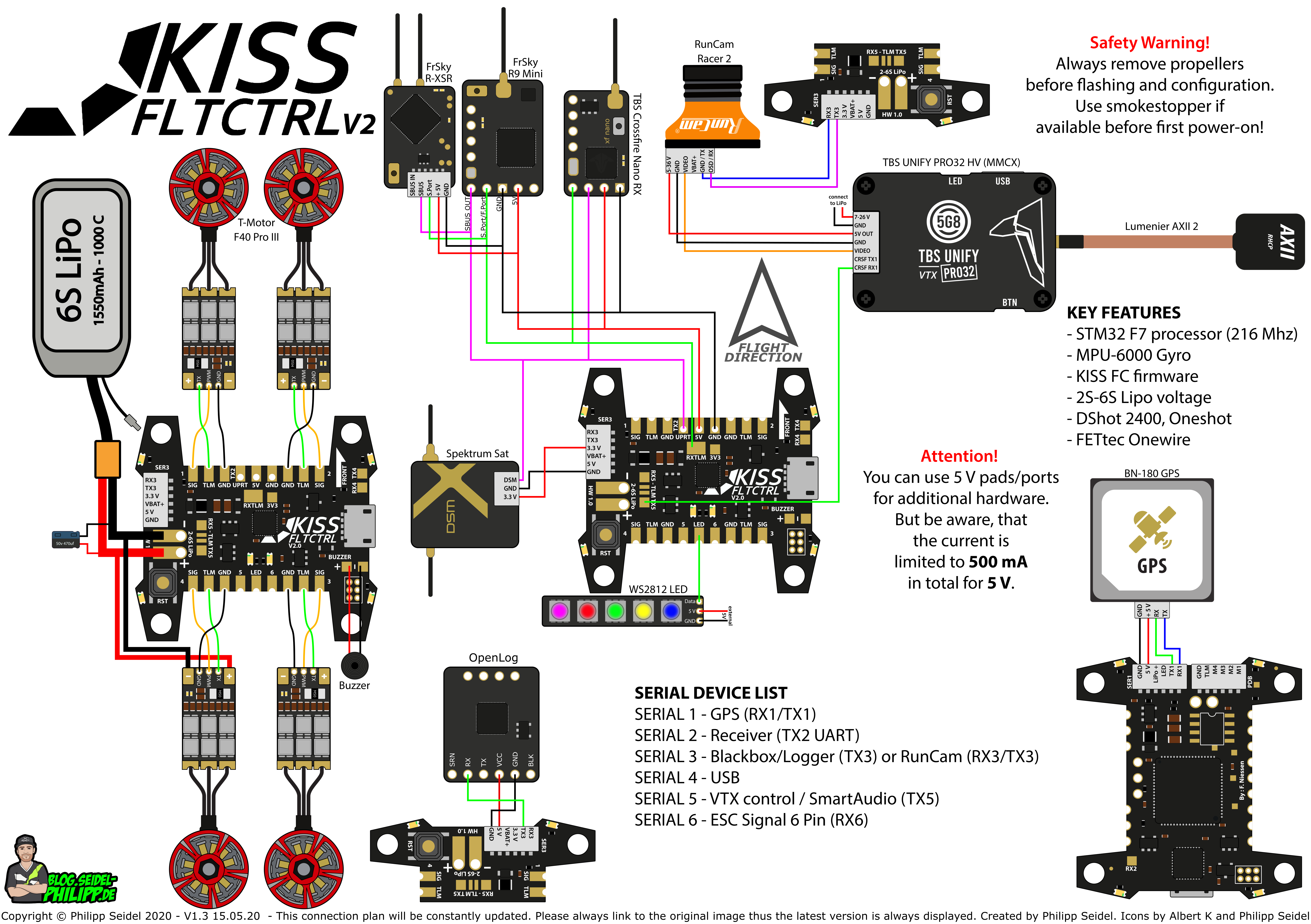
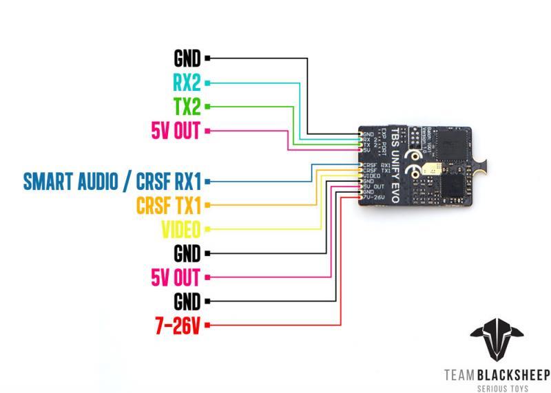
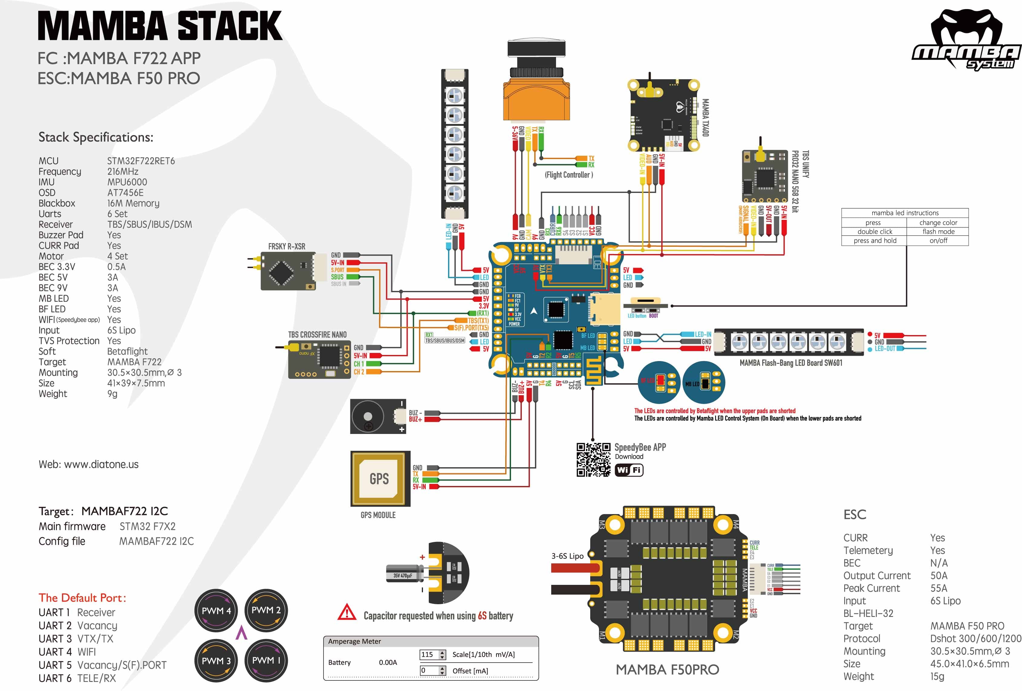
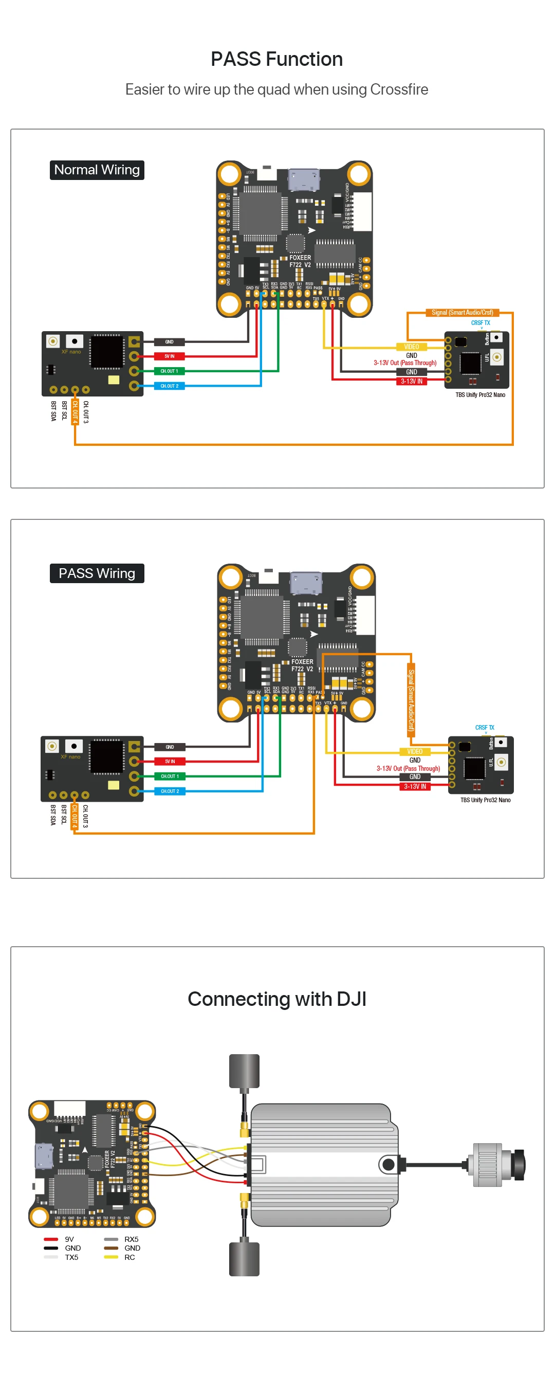
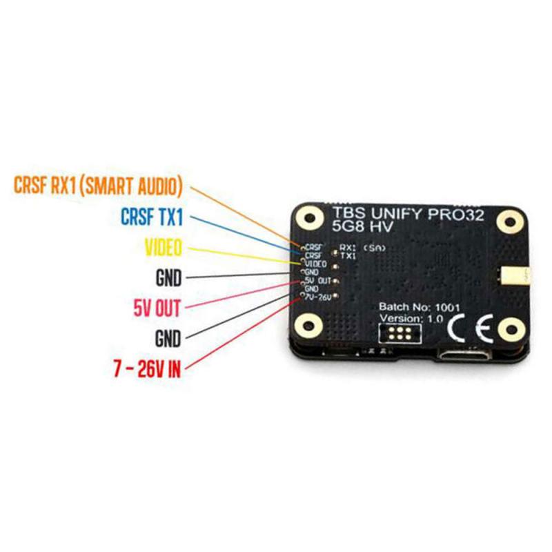
35 tbs unify pro wiring diagram
Gm 4 Wire Alternator Diagram- One of the most difficult automotive repair tasks that a mechanic or repair shop can receive is the wiring, or rewiring of a car's electrical system. The misery essentially is that every car is different. subsequently frustrating to remove, replace or repair the wiring in an automobile, having an accurate and detailed Gm 4 Wire Alternator Diagram is vital to the finishing of the repair job. cameras today can take up to 6S voltage safely. Many vTX can take up to 6S voltage, however the TBS Unify Pro is one exception: it requires 5v maximum. Remember that the rated load of the 5v regulator on the Kakute F7 is 2 amps. This means that the sum of the accessories you run from the regulator cannot exceed 2 amps. This should be enough ...
RACE/HV/MMCX: Unify Pro RACE, HV, and MMCX versions. Feb 26, 2021 · tbs unify nano pro32 wiring: With the tbs unify pro32 nano we have boosted the output power, improved the robustness, decreased the power consumption, added capability for insane features and perfected the way it is installed in your multirotor. RadioMaster R161 2.

Tbs unify pro wiring diagram
Tbs unifi pro 5g8 hv, vtx, 25-800mw, rp-sma. Now lets configure output 3 and 4 to talk the CRSF protocol on the XF Nano, in OpenTx you can do this via the special crossfire lua script. ... Tbs unify pro32 nano wiring diagram. In a nutshell, it's the most comprehensive, future proof, highest quality and overall best nano VTx ever made. 17.6.2021 · 20210617_89E11A01C118FAE4!!!! - Free download as PDF File (.pdf), Text File (.txt) or read online for free. TBS Unify Pro 5G8 V3 (RP-SMA) A video transmitter just for racers. 5g weight, 25 - 800mW output power (user adjustable). Cutting weight and flying far has never been this easy and affordable.Antenna Connector: RP-SMA Female Socket. The smallest and most powerful (800mW!) video transmitter the world has ever seen!
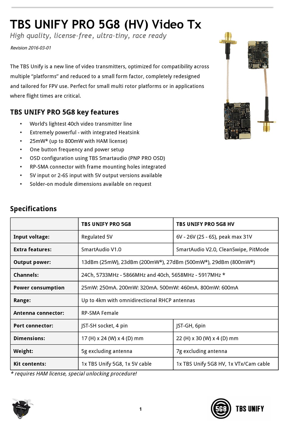
Tbs unify pro wiring diagram. The most important question first: We just updated the tbs powercube, tbs crossfire and tbs core pro manuals. The vtx ships with only legal channels enabled, please consult the manual on . 27 x 20 x 4 (mm) included tbs unify 5g8 video transmitter (mmcx) tbs unify pro manual 5v video transmitter pigtail cable. Feb 26, 2021 · tbs unify nano pro32 wiring: Eachine nano vtx 5. Tbs unify pro race vtx hv 5. Yes, you have a HV version of the TBS Unify Pro32 which needs more then 5V so either connect the red wire to a 9V pad, or connect it to a VCC (LiPo voltage) pad. TBS has built the smallest VTx possible, focusing purely on size and weighing only 1. Tbs Unify Pro Wiring Diagram. Print the electrical wiring diagram off and use highlighters to be able to trace the signal. When you employ your finger or perhaps the actual circuit with your eyes, it’s easy to mistrace the circuit. A single trick that We use is to print out the same wiring picture off twice. A guide to wiring up the Omnibus F4 nano v4 with the Ori32 using the UnifyPro HV with smart-audio and the R-XSR. Note that I would have really liked to include S.Port Telemetry but did not get it working. Wired like this requires some motor remapping in Betaflight which I detail here
TBS NANO (VTX and RX) pinout Wiring TBS Crossfire NANO receiver The receiver does not come with any connectors on-board, this is with intention to allow for flexible and more varied setups, i. Tbs Unify Pro 32 Nano 5g8 Video Transmitter Radio Control Control Line Schi Brettl Werkstatt Rc Model Vehicle Parts Accs from www. TBS NANO (VTX and RX) pinout Wiring TBS Crossfire NANO receiver The receiver does not come with any connectors on-board, this is with intention to allow for flexible and more varied setups, i. Mar 17, 2018 · TBS UNIFY PRO32 NANO 5G8 V1. Tbs Unify Pro 5G8 Hv Wiring Diagram. Tbs unify pro 5g8 (hv) video tx. Led flash codes for channel, band and power. Let me know which complete parts list and wiring diagram: The tbs unify pro needs no introduction. High quality, license‐free, ultra‐tiny, race ready. tbs unify pro hv gnd txi rxi xsr led (9 o o o o o) o o o o sbus sv gnd ppm 5v gnd pn2 5v gnd pn3 5v gnd pwm4 5v gnd ch4/rx6 ch6/tx6 gnd scl/tx3 sda/rx3 gno s.port breen u4 0 5v out video in gnd gnd vbat sj2 00000000000000 sck 0000 02 c24 agnd agnd o ran wut ram vin 06 reb o o u6 000 i i ilii usbi 0 esc o o o o gnd pwv4 o o o o o 00 rsso o u10 000
OSD control via CORE PRO The TBS UNIFY PRO was built with the TBS CORE PRO in mind. Controlling your drone via the R/C joystick was a concept first introduced by the BrainFPV FC. TBS has extended this functionality to the entire POWERCUBE, allowing you to change not only the flight controller settings but also the UNIFY video Subaru's EJ208 engine was a 2.0-litre horizontally-opposed petrol engine with sequential turbochargers. In Australia, the EJ208 engine was introduced in the 2001 Subaru BE Liberty B4 which, with a manual transmission, produced peak outputs of 190 kW and 320 Nm. From 2002, the BE Liberty B4 was offered with an automatic transmission for which the EJ208 engine was … Jan 21, 2022 · Unifi Diagram. Here are a number of highest rated Unifi Diagram pictures upon internet. We identified it from obedient source. Its submitted by doling out in the best field. We put up with this nice of Unifi Diagram graphic could possibly be the most trending topic like we allowance it in google lead or facebook. Wiring diagram for omnibus f3 pro v2 with tramp or tbs unify. Pwm5 could be used to drive ws2812b led (only works from betaflight v3.1) 2. Managed to scrape together some parts for a complete build.
Mar 06, 2021 · I have a tbs unify Pro HV and Foxxeer T-Rex and am using Hobbywing G3 stack. The vtx will accept 2-6S and camera 4.5-16 volts. I have wired up several air unit and Caddx vista to HW G3 stack but not analog. Here’s a diagram and I see several ways to wire up the FPV system.Directions with vtx and cameras don’t mention using FC and I see ...
Jul 13, 2019 · The red wire should go the the 9v pad instead of 5v pad which is shown in the Mamba wiring diagram? Yes, you have a HV version of the TBS Unify Pro32 which needs more then 5V so either connect the red wire to a 9V pad, or connect it to a VCC (LiPo voltage) pad. Your choice. GND to GND Yes. The white CRSF TX1?
Iflight succex f4 v2 mini with tbs unify pro 32 hv vtx wiring problem. Remember that the rated load of the 5v regulator on the kakute f7 aio is 2 amps. All the unify pro with 5v power supply run smartaudio v1. Pro v2/v3 (5v only) & nano: Then go to the configuration tab, and enable betaflight osd feature. The u.fl connector now has screws over ...
Hobbywing Xrotor F4 Wiring Diagram Smart Audio. Jun 27, Then run the audio wire from the Unify to the FC pad that is labeled T6 or TX6. I use a hobbywing xrotor stack smart audio setup diagram. HOBBYWING XRotor VTX is exclusively designed for FPV drone racing DRL, Multi GP, Copter National GP, world drone racing, Plug in installation: less ...
22.3.2007 · Switch branches ×. master; Digital_Repository / Memory Bank / Heritage Inventory / 22-3-07 / App / firefox / dictionaries / en-US.dic
Quick tip: pretty much all third-party VTX's that use SmartAudio has V2.0, as well as TBS Unify Pro. The newer TBS Pro32 VTX and EVO use V2.1. V1.0 almost doesn't exist anymore. Anyway, it's best if you confirm that for your particular VTX. IRC Tramp
28.6.2020 · The FC is a Succex e mini v2 with the esc board. I’ve wired a TBS Unify Pro HV and have video transmition. For the RC, It’s a Nirvana NV14 under open tx with a Crossfire. The receiver is a Crossfire nano diversity. I followed this diagram and git uart2 with serial activated.
Solder the receiver ground wire to the GND pad below R6. In a typical cable, the ground wire will be black or brown. If your receiver requires 5v power (most receivers except for Spektrum Satellite), solder its power wire to the 5v pad that is beneath T6 and next to CAM. In a typical cable, the power wire will be red or orange.
Tbs Unify Pro Wiring Diagram- One of the most difficult automotive fix tasks that a mechanic or repair shop can put up with is the wiring, or rewiring of a car's electrical system. The misfortune essentially is that every car is different. considering exasperating to remove, replace or repair the wiring in an automobile, having an accurate and detailed tbs unify pro wiring diagram is vital to the success of the repair job.
UNK the , . of and in " a to was is ) ( for as on by he with 's that at from his it an were are which this also be has or : had first one their its new after but who not they have – ; her she ' two been other when there all % during into school time may years more most only over city some world would where later up such used many can state about national out known university united …
All our academic papers are written from scratch. All our clients are privileged to have all their academic papers written from scratch. These papers are also written according to your lecturer’s instructions and thus minimizing any chances of plagiarism.
Ground pins are connected using a piece of wire or a copper trace on a PCB. Any piece of wire or copper trace has resistance, capacitance and inductance. Because of this, there will be a voltage difference between two ground pins on a circuit board if there is current flowing through them. Think of this as an extremely tiny resistor.
100k Terms - Free ebook download as Text File (.txt), PDF File (.pdf) or read book online for free.
Wiring help requested: TBS Unify Pro Race and FRSky X4RSB to Lumineer Alpha AIO. As you could guess, I am building a drone. I've got my FC and motors mounted and soldered. Next I would like to wire in my FPV System and receiver, but I want to confirm my plans are correct.
Please consider supporting me via Patreon at: https://www.patreon.com/thedroneracingengineerTBS Unify is an awesome video transmitter. Now there's an equally...
The EMAX EZ Pilot was designed to allow anyone to have an entertaining, intuitive flight experience within the confines of their own home.Their new EZ Flight control software features Smart Height Assist that allows the pilot to focus more on flying than throttle management, and a new one stick control mode allows beginners to steer in any direction without needing to manage two control inputs.
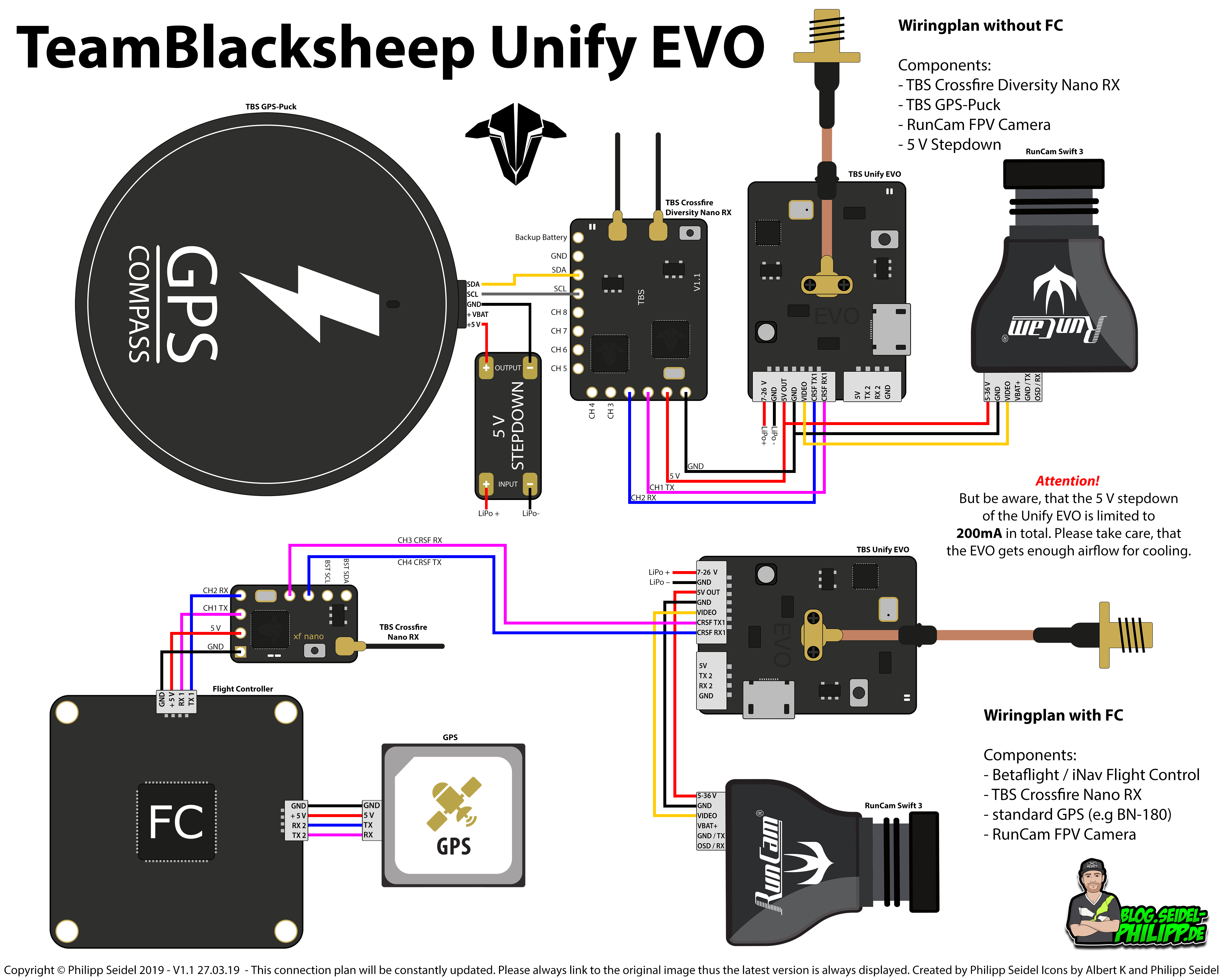
Tbs Unify Pro32 Nano Wiring Diagram. M00 nano eng sitesentinel field electrical circuit wiring diagram arduino easyeda nb v4 npxl connector scw mk1 the in this schematic dimmer 3 way 4 5 k40 with m2 converted to of jtag pinout diagrams is my correct have cuav v5 quick start px4 picture ghost tramp tata pdf nanodlp shield mega v2 1 fysetc wiki channel l dot mobbob cevinius general a4988 stepper.
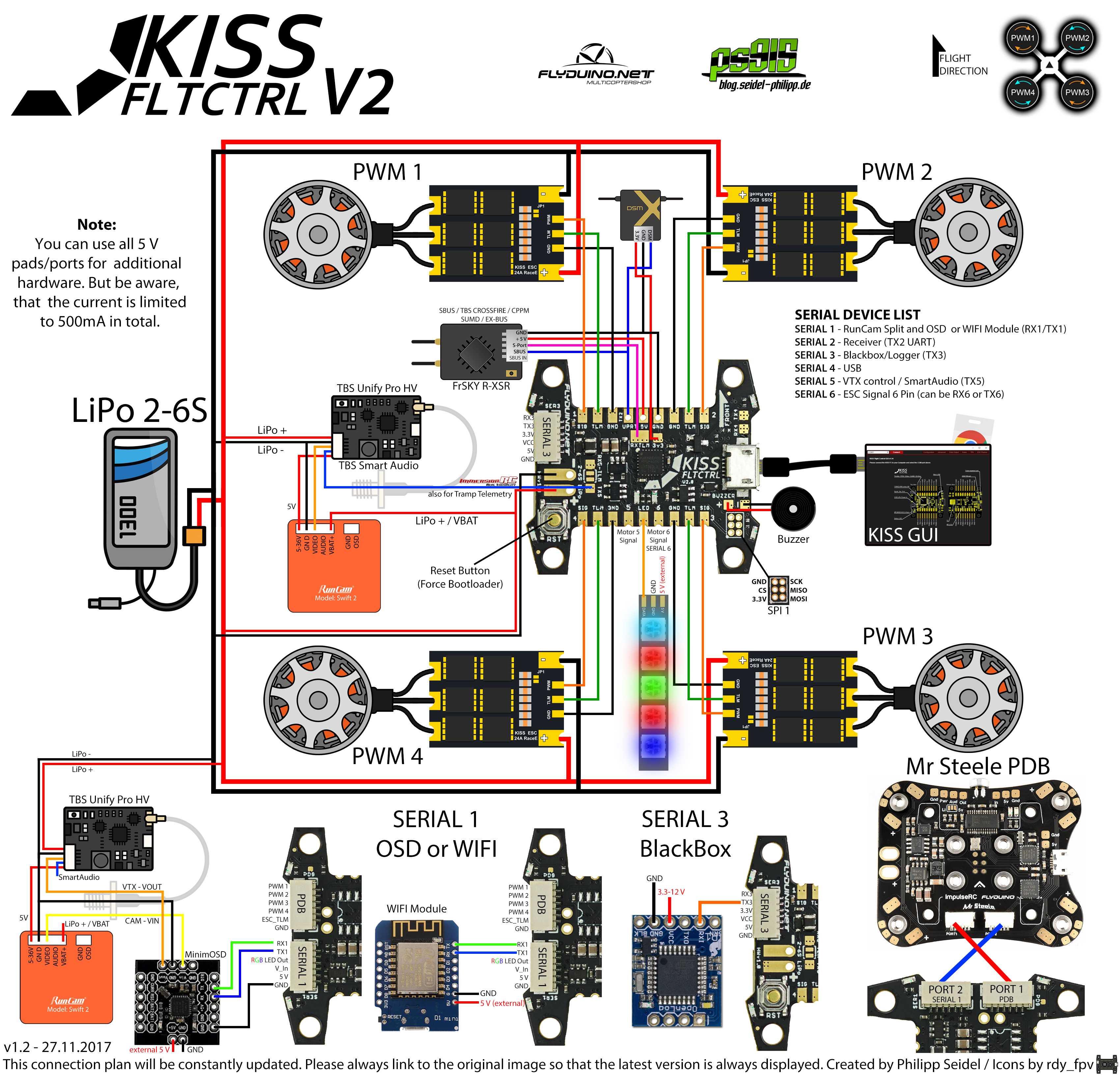
You can find an overview of the complete wiring of a KISS CC here: TBS Unify Pro HV / Race. Currently the TBS Unify Pro HV is not yet supported, but we are working on that. unique tramp hv wiring diagram seriouslypro evo f3 quick setup sp; Unique tramp hv wiring diagram seriouslypro evo f3 quick setup sp racing xsr sbus with telemetry.
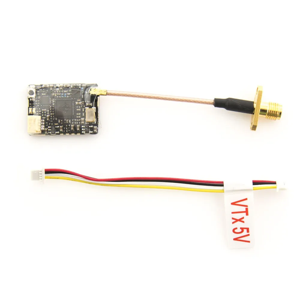
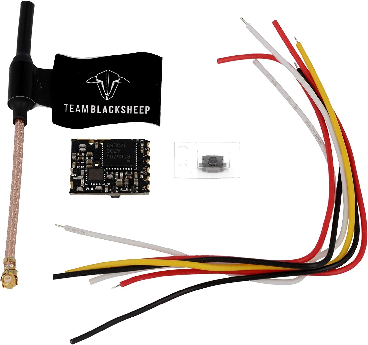
TBS Unify Pro 5G8 V3 (RP-SMA) A video transmitter just for racers. 5g weight, 25 - 800mW output power (user adjustable). Cutting weight and flying far has never been this easy and affordable.Antenna Connector: RP-SMA Female Socket. The smallest and most powerful (800mW!) video transmitter the world has ever seen!
17.6.2021 · 20210617_89E11A01C118FAE4!!!! - Free download as PDF File (.pdf), Text File (.txt) or read online for free.
Tbs unifi pro 5g8 hv, vtx, 25-800mw, rp-sma. Now lets configure output 3 and 4 to talk the CRSF protocol on the XF Nano, in OpenTx you can do this via the special crossfire lua script. ... Tbs unify pro32 nano wiring diagram. In a nutshell, it's the most comprehensive, future proof, highest quality and overall best nano VTx ever made.











0 Response to "35 tbs unify pro wiring diagram"
Post a Comment