35 positive ground wiring diagram
Oct 08, 2021 · The Five Wire Turn Switch Does Not Have The Brake Light Circuit And You Can Only Control The Flow Of Power To Each Rear Light Desc Diagram Turn Ons Stop Light. Introducing Pertronix 1285lsp6 6v Positive Ground Ignitor For Ford Flathead 8cylinder Get Your Car Parts Here And Follow Us For Ford Cylinder Tecumseh Engine. The >white wire is the positive Data wire. (D+). The green wire is the negative. (D-). Both of these wires are involved in data transfer. The red wire is a positive power wire with 5V of DC power that provides power to the USB device. Lastly, the black wire is the ground wire, just like that in any other electrical device (Gnd). If your USB does not follow the above-mentioned wire …
Positive ground wiring Diagram. Title: Microsoft Word - Positive Ground Relay Wiring Schematic.doc Author: Brad Sandberg Created Date: 8/14/2013 5:06:40 P 6 Volt Positive Ground Wiring Diagram from static-resources.imageservice.cloud To properly read a electrical wiring diagram, one has to know how the components inside the program operate.
Positive ground wiring diagram
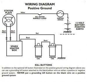
1. See figure B for wiring diagram. 2. Remove the ignition switch wire from the negative coil terminal. 3. Connect the black Ignitor wire directly to the ignition switch wire. 4. Connect the Ignitor black/white wire to negative (-) side of the ignition coil. 5. Connect an insulated, AWG 20 copper stranded wire from the positive coil terminal to ... The wiring diagram shown below was obtained from Pertronix to show the proper hookup for a Pertronix Igniter in a car wired for positive ground, or earth if you prefer. It goes without saying that this is valid only for cars without ballast resistors, viz., our T-series cars. Ford Ranger radio wiring diagram Ranger Tech ('19-'20) Ranger Tech ('83-'11) Product / Build Guide: Other Articles ... , Ground & Illumination: ... 1990-2006 is Positive (1995-1998 is Negative) Dk Green/Orange: Right Front Speaker : 1990-2006 is Negative (1995-1998 is Positive) Gray/Lt Blue: Left Rear Speaker: 1996-2006 is Positive (1999-2000 is Negative) Pink/Lt Green: Left …
Positive ground wiring diagram. Pertronix Ignitor Wiring Diagram - pertronix ignition wiring diagram, pertronix ignitor ii wiring diagram, pertronix ignitor iii wiring diagram, Every electrical arrangement consists of various distinct parts. Each component ought to be placed and connected with other parts in particular manner. If not, the arrangement won't work as it ought to be. Description : Ford 6 Volt Positive Ground Wiring Diagram Gmc Truck Radio Wire inside 6 Volt Positive Ground Wiring Diagram, image size 3804 X 1968 px, and to view image details please click the image. Here is a picture gallery about 6 Volt Positive Ground Wiring Diagram complete with the description of the image, please find the image you need. 04.05.2020 · Door Locks - 5 Wire Alternating 12 Volts Positive (Type C) Relay Wiring Diagram: The switch, when moved in either direction, applies both power and ground directly to motor legs without the use of any relays. Except, at the switch in this case, both motor legs rest at ground . Therefore it is only necessary to change the polarity of one motor ... Wiring Diagram Jds3462 Fuel Positive Ground. The Ignitor is designed for 6-Volt positive ground systems. 2. See Chart on back page for coil recommendations. 4. See figure B for wiring diagram. 2. Positive ground electrical system in old cars. Since the beginning of automotive history, both negative and positive ground polarity have been used by ...
TYPICAL WIRING DIAGRAM (WITHOUT COWL LAMPS) beginning in February 1929. About Ford Wiring • Wires were cloth covered, rubber insulated • Ford used 16 gauge wire on lamp wiring ... 6V ground is Positive • Keep electrolyte levels correct - distilled water • Caps in place Positive ground in automobiles was mostly abandoned with the introduction of 12-volt electrical systems in the fifties. 1955 was pretty much the last use of 6-volt electrics in American-made cars. Most cars switched from 6 volt positive ground to 12 volt negative ground together. One exception to this was the 1955 Packard, switching from 6v to ... Re: 6 volt positive ground battery ignition schematic? On a 6 volt positive ground battery ignition the + goes to the distibutor. Last edited by Barnyard on Tue Jun 12, 2012 3:03 am, edited 1 time in total. There are two ways to get enough Cubs. One is to continue to accumulate more and more. Badland 3500 Winch Wiring Diagram. According to the diagram below, attach the cables from the solenoid to the battery and connect the yellow/blue cables to the winch’s respective terminals. The circuit breaker is then attached to the positive terminal on the battery, and the other end is attached to the solenoid.
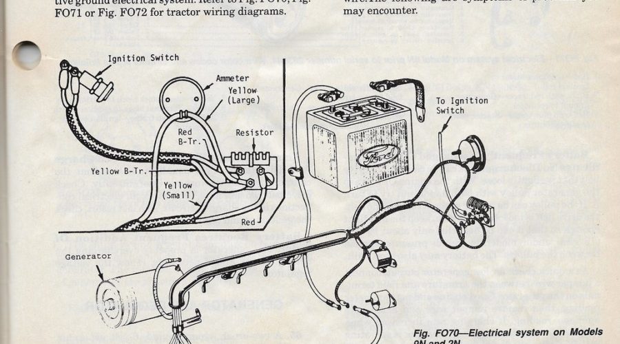
4,465 Posts. #3 · May 21, 2015. A couple of variables whether it's positive or negative ground. If it has the original generator on it then it should be positive ground. If it has been converted to an alternator then it will most likely be negative ground. The starter doesn't care which way it's hooked. J. Wiring Diagram For Ford 9N - 2N - 8N - Readingrat for 6 Volt Positive Ground Wiring Diagram by admin From the thousand photographs on-line about 6 Volt Positive Ground Wiring Diagram, we all choices the best libraries with greatest image resolution just for you all, and this images is actually among pictures selections inside our finest images gallery about 6 Volt Positive Ground Wiring ... This wiring diagram is for use in the installation of a Dynamator in a Tcar wired for positive ground and an ammeter. The relay that is shown in the wiring diagram is provided by Accuspark for use in positive ground systems. The wiring diagram is shown with the permission of Mort Resnicoff. DR _____ WIRING DIAGRAM INFORMATION 8W01 - 9 • Ohmmeter - Used to check the resistance between two points of a circuit. Low or no resistance in a circuit means good continuity. CAUTION:Mostof the electricalcomponents usedintoday’s vehiclesare Solid State.
INSTALLING A KILL BUTTON ON ELECTRONIC IGNITION | JRC ...
13.01.2016 · For those DIY stereo installers, our Silverado Stereo Wiring diagram can give you the information you need. Quickly and easily identify your speaker wires, and what’s needed to wire up your radio. This guide comes in handy whether you are installing a navigation system, MP3 player or even putting the factory stereo back in. Installing a stereo into your Chevy …
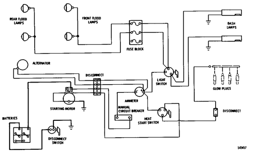
WIRING DIAGRAM--24 Volt System Serial No. 69H2266-Up 951B ...
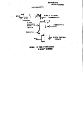
With a positive ground system, the polarity is reversed from a negative ground system. In other words, the flow of electrons goes in the other direction. To get the polarity of the coil correct, the positive side of the coil goes to the points and the negetive side goes to the ignition switch. A distributor is divided in to two different ...
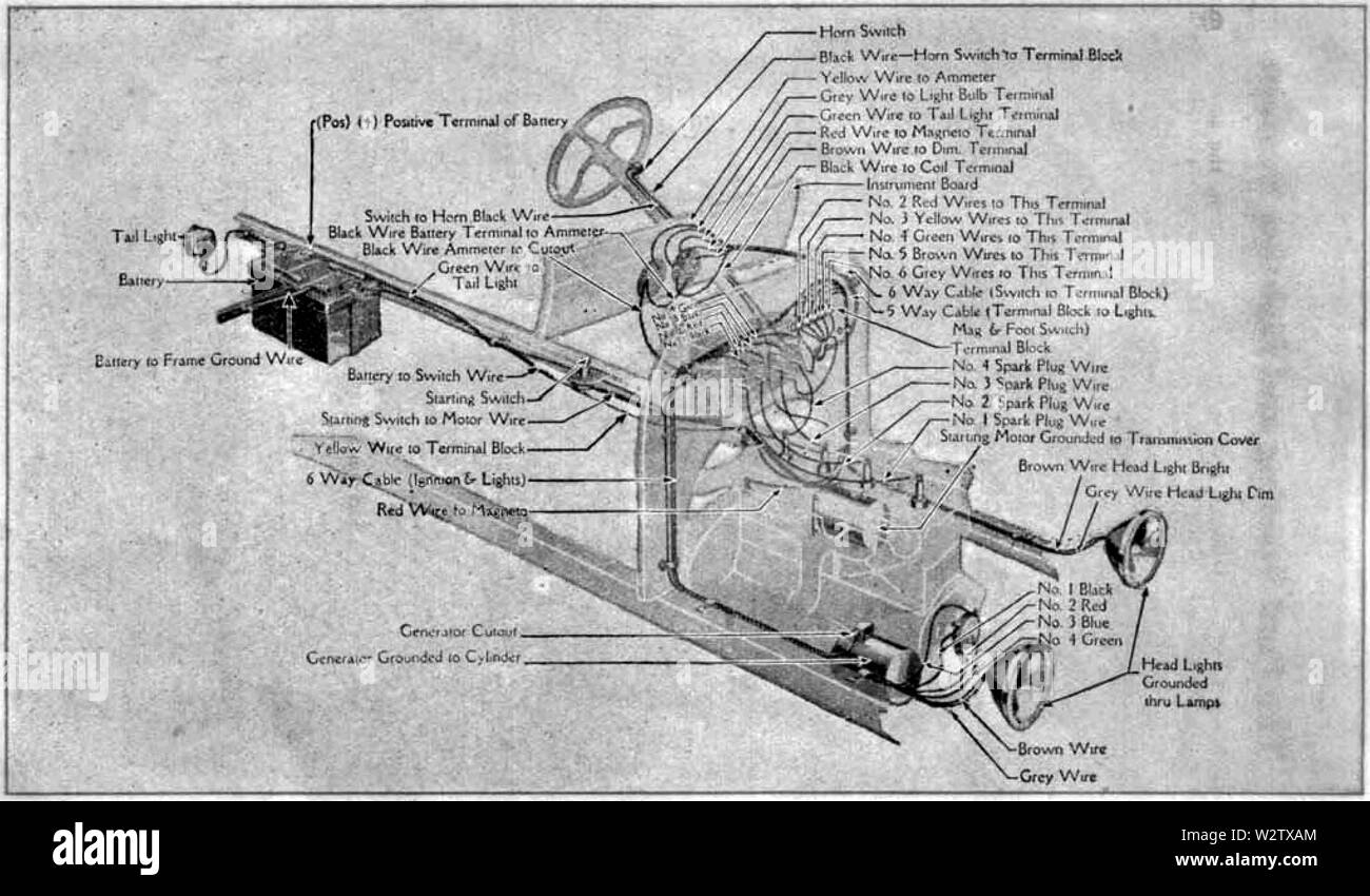
Ford model t 1919 d055 wiring diagram of cars equipped with a ...
Positive Ground Farmall H Wiring Diagram 6 Volt from usguidebook.comeluxitalia.it. Print the wiring diagram off and use highlighters in order to trace the signal. When you employ your finger or even stick to the circuit with your eyes, it's easy to mistrace the circuit. One trick that We use is to print exactly the same wiring picture off twice.

Positive to Negative Ground Conversion
6 volt positive ground wiring diagram - You will need a comprehensive, skilled, and easy to comprehend Wiring Diagram. With this sort of an illustrative manual, you will have the ability to troubleshoot, stop, and complete your tasks with ease. Not only will it help you accomplish your desired outcomes more quickly, but also make the complete ...
6v, 12v negative or positive ground? - Yesterday's Tractors
1 Start by connecting the ground clamp of your test light to the negative battery post and touch the point to the positive post to make sure the test light lights up. 2 Now touch the test light to the dump trailer solenoid positive battery cable light should be on. 3 When you push the up or down button while touching the Small White wire at the motor solenoid the pump motor should run. If …
6 or 12 VOLT POSITIVE GROUND WIRING
Title: Microsoft Word - Positive Ground Relay Wiring Schematic.doc Author: Brad Sandberg Created Date: 8/14/2013 5:06:40 PM

1965 T120 Custom Wiring - No Battery | Triumph Rat Motorcycle ...
25.01.2022 · The ground points circuit diagram shows the connections from all major parts to the respective ground points. When troubleshooting a faulty ground point, checking the system circuits which use a common ground may help you identify the problem ground quickly. The relationship between ground points ( , and \oy shown below) can also be checked this way.
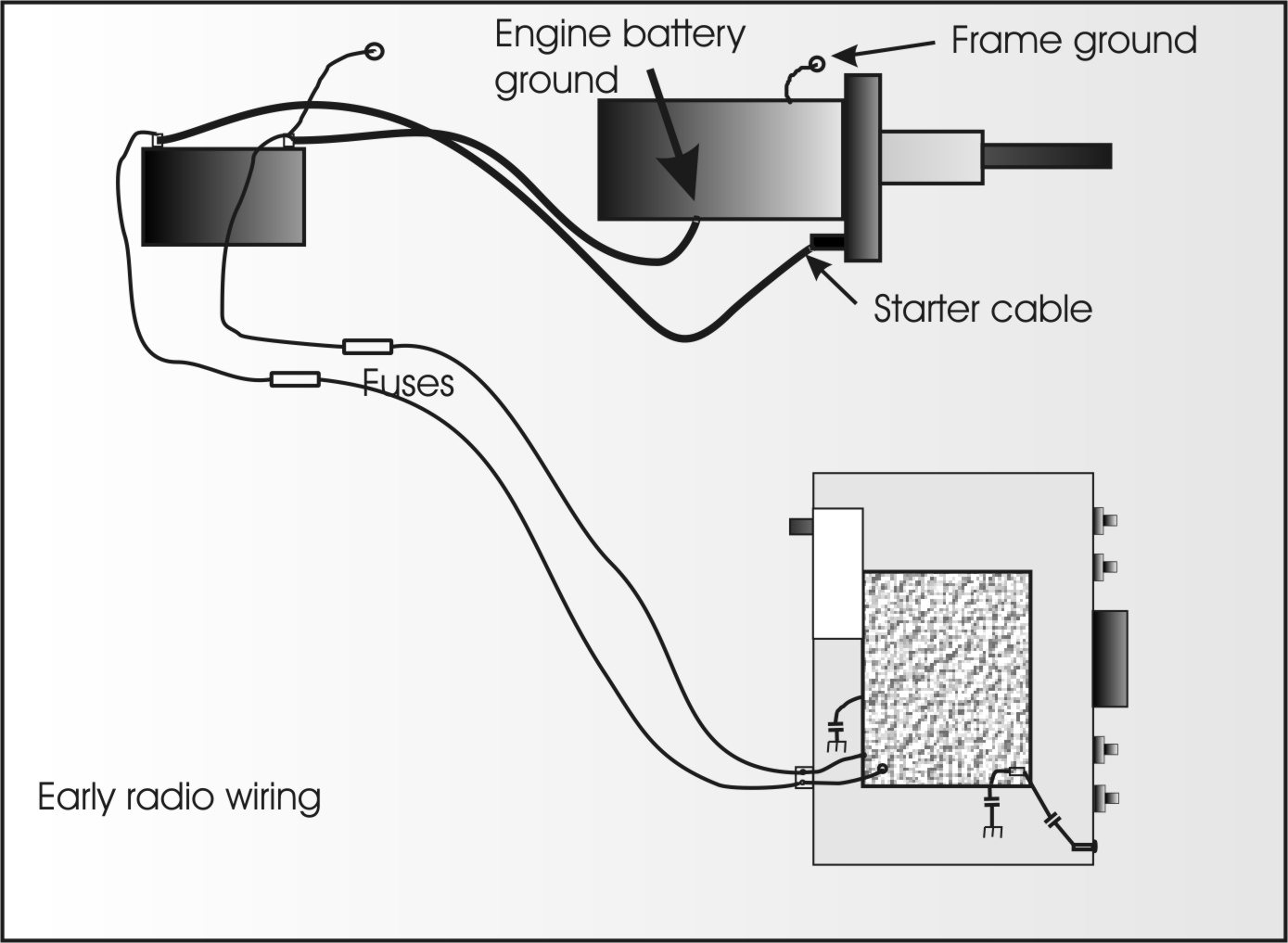
Mobile Radio Wiring and Grounding
The diagram above is the 5 pin relay wiring diagram. There are different kinds of relays for different purposes. It can be used for various switching. Relay can be the best option to control electrical devices automatically. 5 pin is compromised of 3 main pins and an SPDT (single pole double throw). So, a single pole double throw has a mutual point and two other points …
Bob Johnstones Studebaker Resource Website (Wiring Diagram ...
With the coil being correct for negative ground before and the wiring diagram from the GSS-1411 76 revised service manual seems to match my tractor exactly. The ground wire to the battery is red and the wire to the tractor is black, looks like someone just put the battery in wrong. Glad to hear it hasn't hurt anything.
6 Volt Generator "TO" 6 Volt Alternator Conversion, Farmall M ...
6 Volt Positive Ground Wiring Diagram - wiring diagram is a simplified conventional pictorial representation of an electrical circuit. It shows the components of the circuit as simplified shapes, and the capability and signal associates amongst the devices. A wiring diagram usually gives guidance about the relative viewpoint and arrangement ...
1950 Farmall Cub
Nov 03, 2021 · Connect the one wire off the post on the new positive ground alternator with a 10 gauge wire to the top terminal of the ammeter as shown on your diagram. As I said in other replies if your electronic ignition was connected per the manufacturer and the tractor ran fine as you stated several times keep it connected as before and enjoy.
Help me understand the relationship between positive ...
Grote's Answer. A Turn Signal Switch is just a collection of mechanical gates and are not polarity sensitive. In this case, this switch has an indicator bulb, which is incandescent and also not polarity sensitive. So, in relation to the wiring for the switch it should not require any changes, since it is just a matter of continuity.

wiring diagram generator - AllisChalmers Forum
Oct 26, 2021 · 6 Volt Positive Ground Wiring Diagram Fuel Tank | Wiring Diagram – 6 Volt Positive Ground Wiring Diagram. Wiring Diagram consists of several in depth illustrations that show the link of various products. It contains instructions and diagrams for different varieties of wiring methods as well as other items like lights, home windows, and so on.
Pazon Surefire Installation Guide | JRC Engineering, Inc.
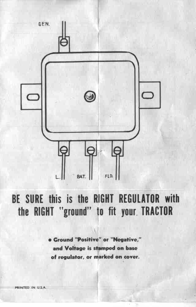
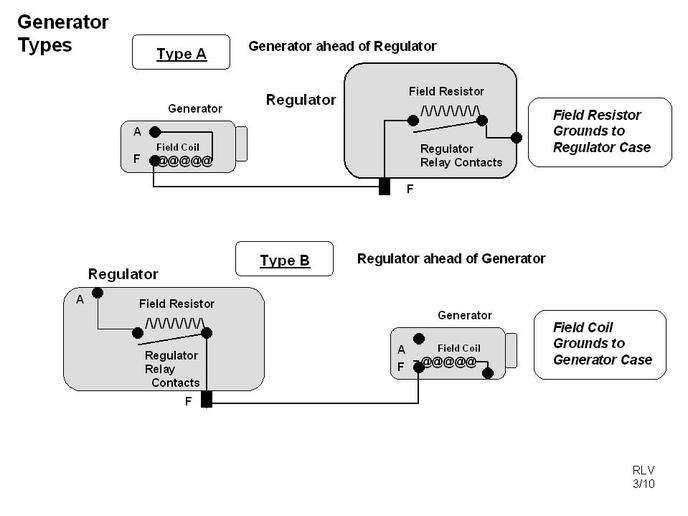
Wiring Diagram For 6v Tractor Voltage Regulator Positive Ground Solenoid Start. This walk-thru is based on the original 8N tractor 6 volt wiring. Many of those were later converted to the 8N type generator and voltage regulator, so this Two small screw terminals on the side of the generator are for "Ground" and " Field".
Positive Ground Dynamo to Alternator conversion : The 3000 ...
14.12.2021 · This wiring diagram is for RV's with factory 50A shore power and will show you what you need to install up to 1200W solar and a 3000w Inverter to your existing electrical system.
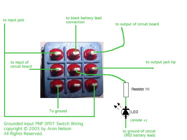
Positive ground Fuzz Face offboard wiring clarification needed.
Positive ground simplified. July 27, 2018 by bugeyeguy. Believe it or not, wiring a car with positive ground is supposed to make them rust less. Doesn't seem to work very well… my first car, a (positive ground) 1966 MGB came to me with rocker panels completely absent, as though they had vaporized. At the time the car was only 12 year old!
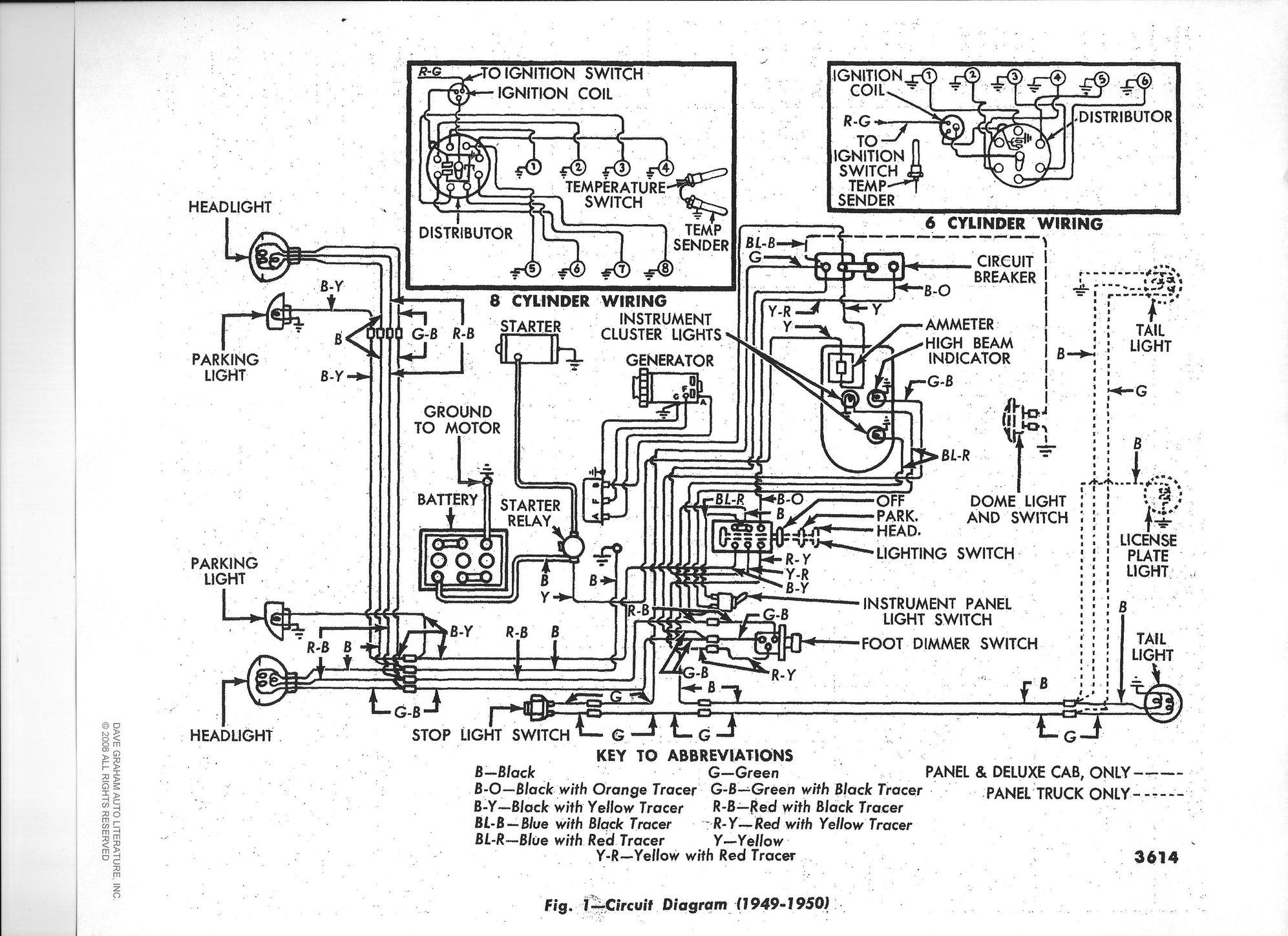
50 f3 wiring diagram - Ford Truck Enthusiasts Forums
The positive ground method was common before the year 1954, and many vintage or classic cars, especially those from the United Kingdom, adopted the positive grounding system. Most modern vehicles use a negative ground system that involves wiring the vehicle chassis to the negative side of the battery, and this has many advantages over positive ...
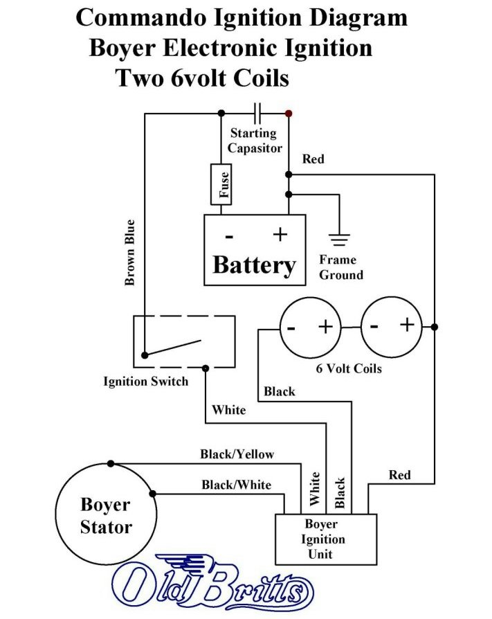
Old Britts, Simplified Wiring Diagrams
6 Volt Positive Ground Wiring Diagram - 6 volt positive ground generator wiring diagram, 6 volt positive ground wiring diagram, Every electrical arrangement is made up of various distinct pieces. Each component should be set and linked to different parts in specific manner. Otherwise, the structure will not work as it should be.

I have a Farmall Model that I want to change from the 6-volt ...
12 Volt Conversion Kit For Allis Chalmers Wd found in: Wiring Harness Diagrams - Antique Tractor Blog, Electronic Ignition Conversion Kit, 6 volt positive ground. Allis Chalmers Wiring Diagram Six Volt Coil Dist by A L. 1 photos. So do you all know of any wiring diagram so I can check to see if it is wired or diagram of how the wiring should be ...
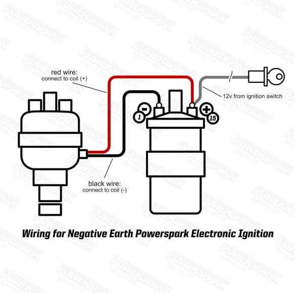
How to fit a Powerspark electronic ignition kit: | Powerspark ...
Other than mounting the solenoid separate from the starter, the wiring is the same as the side-distributor 8N tractor. diagrams show the BEST way that I have found to convert your 6 Volt, Positive Ground, N-Series Tractor to 12 Volts, Negative Ground.A tractor's regulator takes the voltage provided by the battery, manages it by reducing it, and ...
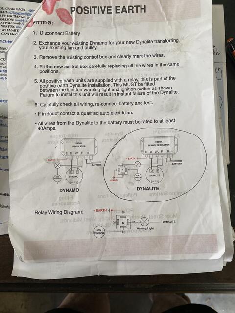
AccuSpark Positive earth fitting instructions
The Ignitor is designed for 12-Volt positive ground systems. 2. Leaving the ignition "ON" with the engine "OFF" for an extended period could result in permanent damage to the Ignitor. ... See figure "B" for wiring diagram. 2. Remove the ignition switch wire from the negative coil terminal. 3. Connect the ignition switch wire ...
12 v positive or negative ground - Yesterday's Tractors
Ford Ranger radio wiring diagram Ranger Tech ('19-'20) Ranger Tech ('83-'11) Product / Build Guide: Other Articles ... , Ground & Illumination: ... 1990-2006 is Positive (1995-1998 is Negative) Dk Green/Orange: Right Front Speaker : 1990-2006 is Negative (1995-1998 is Positive) Gray/Lt Blue: Left Rear Speaker: 1996-2006 is Positive (1999-2000 is Negative) Pink/Lt Green: Left …

Positive to Negative Ground Conversion
The wiring diagram shown below was obtained from Pertronix to show the proper hookup for a Pertronix Igniter in a car wired for positive ground, or earth if you prefer. It goes without saying that this is valid only for cars without ballast resistors, viz., our T-series cars.

Ballast Resistor in a 6 volt system? | The H.A.M.B.
1. See figure B for wiring diagram. 2. Remove the ignition switch wire from the negative coil terminal. 3. Connect the black Ignitor wire directly to the ignition switch wire. 4. Connect the Ignitor black/white wire to negative (-) side of the ignition coil. 5. Connect an insulated, AWG 20 copper stranded wire from the positive coil terminal to ...

Motorcycle Wiring Diagram for Android - APK Download
I'm a newbie wishing to know what I have. (2013) | Page 9 ...

Help needed! Fordson Dexta wiring diagram says ground is ...

Hot-Spark, ignition products. Installation instructions
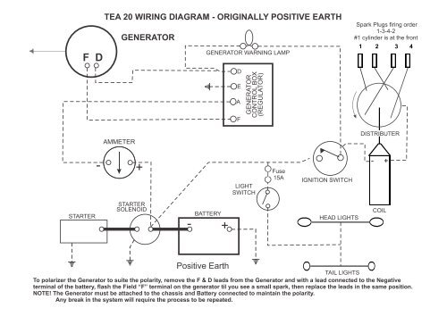
TE20 Generator and Alternator wiring diagrams

12v positive ground wiring question - Farmall Cub

6V Starting and Charging Issues on 1954 Windsor - Chrysler ...
B.B. - 6 VOLT ELECTRICAL TIPS & TRICKS - The Flat-Spot
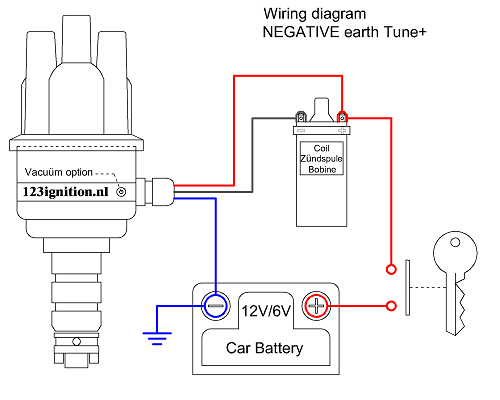
123 Wiring Diagrams
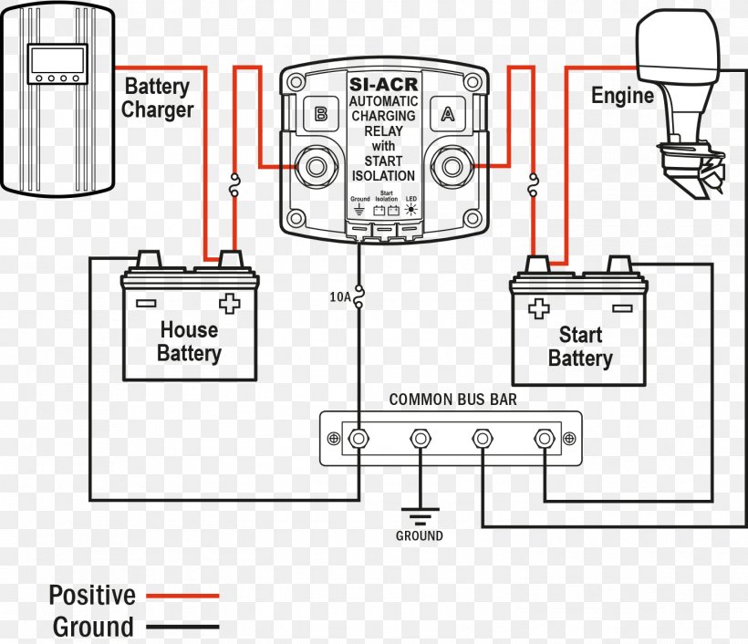
Battery Charger Wiring Diagram Battery Management System ...

Understanding Guitar Wiring, Part 7: Output Jacks - StewMac
0 Response to "35 positive ground wiring diagram"
Post a Comment