39 auto meter wire diagram
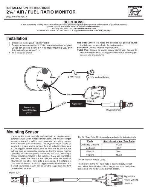
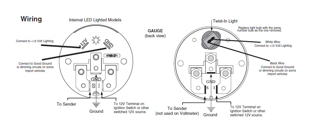
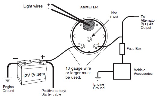
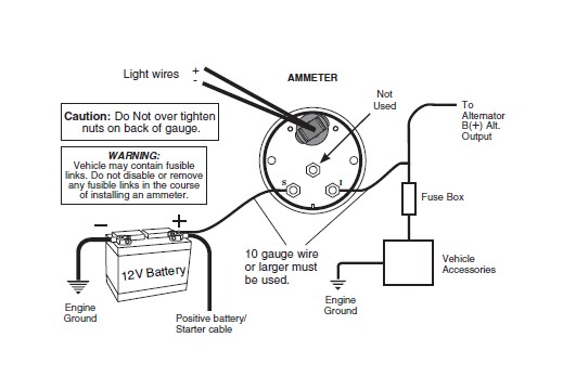
Autometer Pro Comp Ultra Lite Wiring Diagram Fresh Auto Meter Wiring - Autometer Gauge Wiring Diagram. Wiring Diagram arrives with several easy to follow Wiring Diagram Guidelines. It's intended to aid all the average person in developing a suitable method. These guidelines will be easy to understand and apply. Pictured below is a copy of the wiring diagram for the Autometer Oil Pressure Gauge. To install an oil pressure gauge you will first need to purchase one. Pictured below is a copy of the wiring diagram for the Autometer Oil Pressure Gauge. left is labeled 'S', signal wire from oil pressure or water temp sensor? .
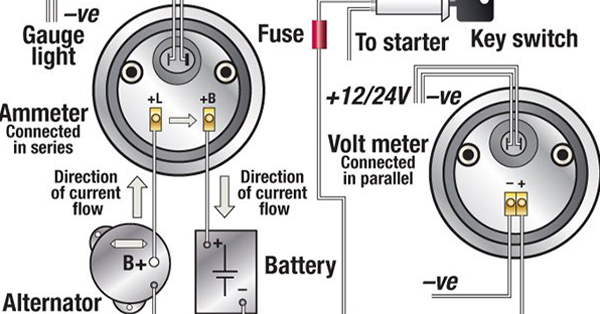
The wiring diagram shown is a typical installation. For Chrysler Blue, Gold and Silver Boxes, Ford Standard Electronic ... Auto Meter Products, Inc. warrants to the consumer that all Auto Meter High Performance products will be free from defects in material and workmanship for a period of twelve (12) months from date of the ...

Auto meter wire diagram
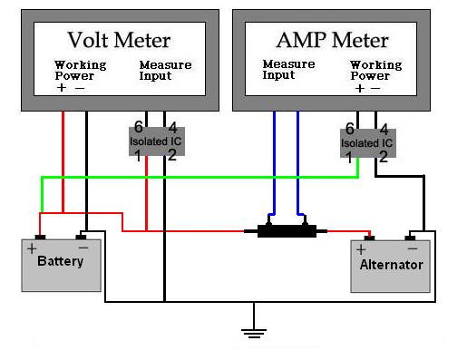
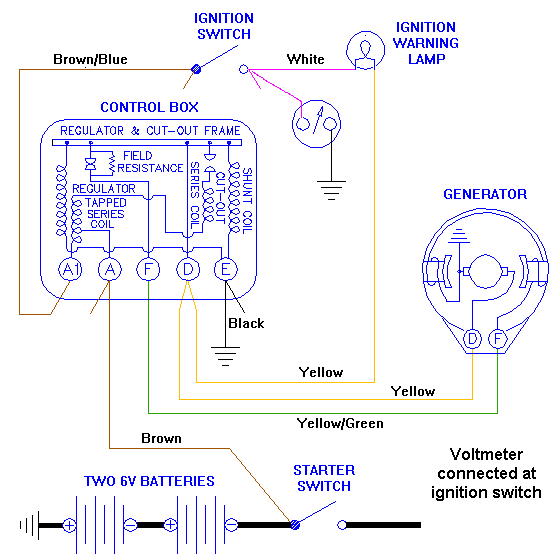
Autometer voltmeter wiring diagram. Voltmeter wiring figure 5. Voltmeter wiring figure 5. Voltmeter instructions wire nut flat washer nut washer voltmeter grommet u bracket do not leave any hardware out of these connections diagram 1 ground source step 2 should be connected as shown in diagram 1 to the voltmeter s connection post marked. 1 16 ... Recommended - Auto Meter Hall effect sender, 3-wire 16 pulses/revolution. Standard 7/8 - 18 thread 5292 Ford, plug in GPS Interface Module Universal Speed Sensor 3299 Optional Tach/Speedo Gauge Connector ... Wiring - Diagram 1 SIG Engine Dash Lighting Ground GND +12V GND LAMP OUT White Wire: Connect to +12 Volt Lighting. INSTALLATION INSTRUCTIONS. SHORT SWEEP ELECTRIC GAUGES. 2650-1079-00 Rev. C. Mounting. Replace light bulb with the same . number bulb as the one removed. These gauges can be mounted in-dash or in Auto Meter mounting solutions (panels, cups, pods, etc.). 2. 1 ⁄ 16" diameter gauges mount in 2. 1 ⁄ 16 ...
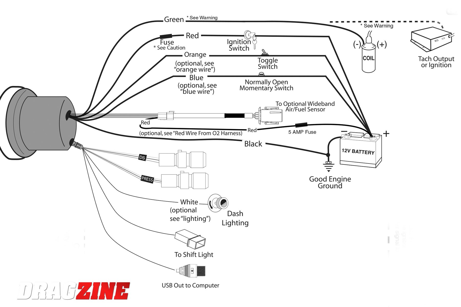
Auto meter wire diagram. Ferguson TO-20 Wiring and Ammeter Installation At a recent meeting of FENA members in Wakarusa IN Brian Schultz of Hamlet IN raised a question about the wiring diagram for the TO-20. Auto Gauge Tach Wiring Wiring Diagram Data Autometer Gauge Wiring Diagram Wiring Diagram consists of numerous in depth illustrations that show the connection of ... Autometer Tach Wiring Diagram Auto Meter Sport P Electrical Drawing Rh G News Co on random diagrams, auto meter monster tach wiring diagram diagrams.A tachometer is a good addition to any vehicle equipped with a manual transmission. In my Jeep CJ-7, I didn't have one of those rare factory tachs so I chose the Autogage Tachometer /4 inch with an ... Connect this to the signal wire at your speed sender/sensor. If you are using a computer (ECM, PCM, ECU, etc), you may connect this to the factory speed signal wire at the computer instead of the speed sensor if it is equipped. Consult a diagram for your computer to verify. Blue: Oil PSI sender wire. Connect this to the Auto Meter oil pressure ... Recommended - Auto Meter Hall effect sender, 3-wire 16 pulses/revolution. 5291 Standard 7/8 - 18 thread 5292 Ford, plug in Mounting 1. 8Mount speedometer in a 33/ " dia. hole. Be careful not to cut the hole too large. 2. 8Cut a 3/ " dia. hole in the firewall for the speedometer wires. Place a rubber grommet in the hole and route
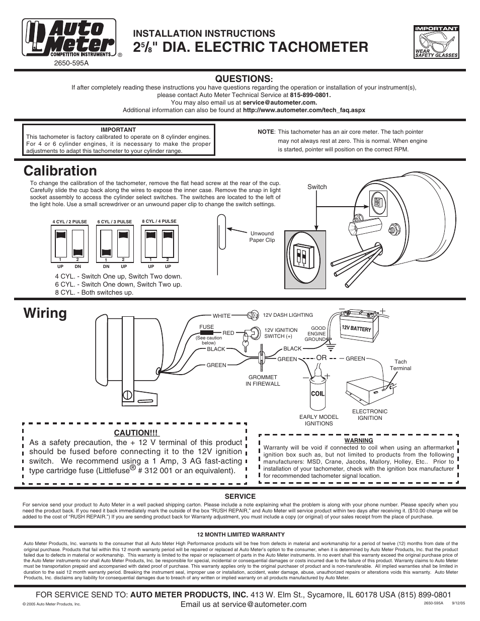
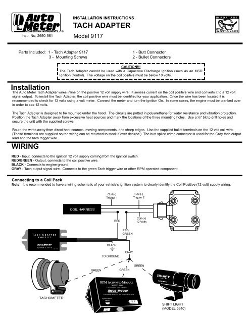
while FoR SERViCE SEND To: AUTO METER PRODUCTS, INC. 413 W. Elm St., Sycamore, iL 60178 USA (866) 248-6357 Email us at service@autometer.com 2650-1244-00 Rev. B 3/30/09 SERVICE For service send your product to Auto Meter Products, inc. in a well packed shipping carton. Autometer Sport Comp Tach Wiring Diagram. Wiring. The special design of the tachometer base allows for a variety of mounting For service send your product to Auto Meter in a well packed shipping carton. To operate the Sport-Comp Shift-Lite tachometer, first determine your desired. Sport-Comp Playback Tachometer · DPSS Shift-Light - Level 2 or ... 2650-1684-00 Rev. A 11/6/13 FOR SERVICE SEND TO: SPEK-PRO SERVICE • 413 West Elm Street • Sycamore, Illinois 60178 USA www.spekpro.com • sevice@autometer.com • (866) 248-6357 12 MONTH LIMITED WARRANTY Spek-Pro/Auto Meter Products, Inc. warrants to the consumer that all Auto Meter High Performance products will be free from defects in material and workmanship for a period of twelve (12 ... Autometer Tach Wiring Diagram - autometer diesel tach wiring diagram, autometer phantom tach wiring diagram, autometer playback tach wiring diagram, Every electrical structure is composed of various diverse parts. Each component ought to be set and linked to different parts in particular way. If not, the structure won't work as it ought to be.
Autometer tach wiring diagram. For chrysler blue gold and silver. The wiring diagram shown is a typical installation. Figure a figure c. A wiring diagram is a simplified traditional pictorial depiction of an electrical circuit. The tach must be returned to autometer for a light replacement. Toll free tech support. A wiring diagram is a simplified conventional photographic representation of an electrical circuit. 8mount speedometer in a 33 dia. The electronic speedometer in this instrument is designed to operate with an electrical speed sender. W auto meter gps interface. Place a rubber grommet in the hole and route. Autometer Basic Tach Installation Wiring Instructions Tutorial How-To http://www.jegs.com/webapp/wcs/stores/servlet/KeywordSearchCmd?manufacturer=Auto%20Mete... 2 5/8" Electric Speedometer, 3 wire with green signal wire. 2-5/8" Electric Speedometer, 4-wire with purple signal wire. 3 3/4" & 5" Electronic Speedometer. Tach/Speedo Combo.
Auto Meter Products. 413 W Elm St. Sycamore, IL 60178. Toll Free Tech Support: 866.248.6357. Toll Free Customer Service: 866.248.6356. International: 815.895.8141
Autometer Gauge Wiring Diagram - auto meter gas gauge wiring diagram, autometer amp gauge wiring diagram, autometer boost gauge wiring diagram, Every electric structure consists of various unique pieces. Each part should be placed and linked to other parts in specific manner. Otherwise, the structure won't work as it should be.
Autometer Sport Comp Tach Wiring Diagram. As a safety precaution the RED wire of this product should be fused before connecting it to the positive (+) side of switched power source. We recommend using. Any Auto Meter Shift-Lite™, or Quick-Lite™ Shift-Lite can be used with tachs 2) Pass tach wires through shock strap assembly and slide tach ...
White Wire: Connect to +12 Volt Lighting. INSTALLATION INSTRUCTIONS. SHORT SWEEP ELECTRIC GAUGES. 2650-1079-00 Rev. C. Mounting. Replace light bulb with the same . number bulb as the one removed. These gauges can be mounted in-dash or in Auto Meter mounting solutions (panels, cups, pods, etc.). 2. 1 ⁄ 16" diameter gauges mount in 2. 1 ⁄ 16 ...
Recommended - Auto Meter Hall effect sender, 3-wire 16 pulses/revolution. Standard 7/8 - 18 thread 5292 Ford, plug in GPS Interface Module Universal Speed Sensor 3299 Optional Tach/Speedo Gauge Connector ... Wiring - Diagram 1 SIG Engine Dash Lighting Ground GND +12V GND LAMP OUT
Autometer voltmeter wiring diagram. Voltmeter wiring figure 5. Voltmeter wiring figure 5. Voltmeter instructions wire nut flat washer nut washer voltmeter grommet u bracket do not leave any hardware out of these connections diagram 1 ground source step 2 should be connected as shown in diagram 1 to the voltmeter s connection post marked. 1 16 ...










0 Response to "39 auto meter wire diagram"
Post a Comment