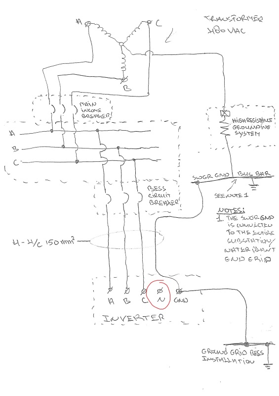
36 high resistance grounding system diagram
Generally speaking, there are two types of resistors used to tie an electrical system's neutral to ground: low resistance and high resistance. Ground fault ...4 pages by D Murray · 2009 · Cited by 12 — gineering oversights in the design of HRG systems are addressed, ... Simplified one-line diagram for isolated redundant UPS system.9 pages
due to a second ground fault is High Resistance Grounding as referenced by ... diagram on the left represents a TVSS on a solidly grounded system while that ...6 pages

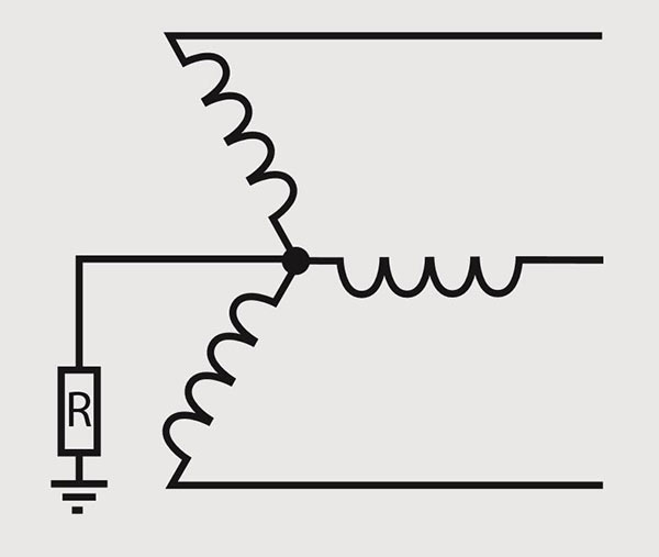
High resistance grounding system diagram
Why Neutral Grounding or Neutral Earthing is Essential?

High Resistance Grounding System Diagram - Diagram ...

Erosion Explosion 💥 The ocean takes back the land. One grain at a time â³

Andromeda galaxy
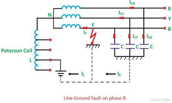
What is Peterson Coil Grounding? - Circuit Globe
High Resistance Grounding

30 High Resistance Grounding System Diagram - Wiring ...

High Resistance Grounding System Diagram - General Wiring ...
High Resistance Grounding System Diagram - Diagram ...

High Resistance Grounding System Ground Fault Detection ...

My first view of the Slovakian countryside.

Two Seasons
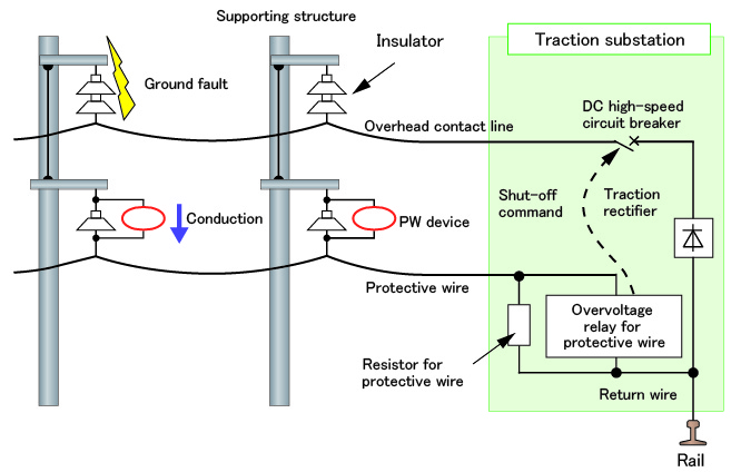
Major Results of Research and Development in Fiscal 2013 I-7

High Resistance Grounding System Diagram - Hanenhuusholli
ignition waveforms - Lixin Advanced Engine Management ...

High Resistance Grounding System Diagram - Wiring Diagram ...
Resistor vs. Reactor - Which Transformer Neutral Grounding ...

Figure 3 from Phasor diagram of a single-phase-ground ...

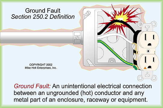
An Overview Of Grounding System (Grounded)

High Resistance Grounding System Ground Fault Detection ...

Figure 1 from Ground fault location self-diagnosis in high ...
Conversion of a solidly grounded system into an HRG system ...
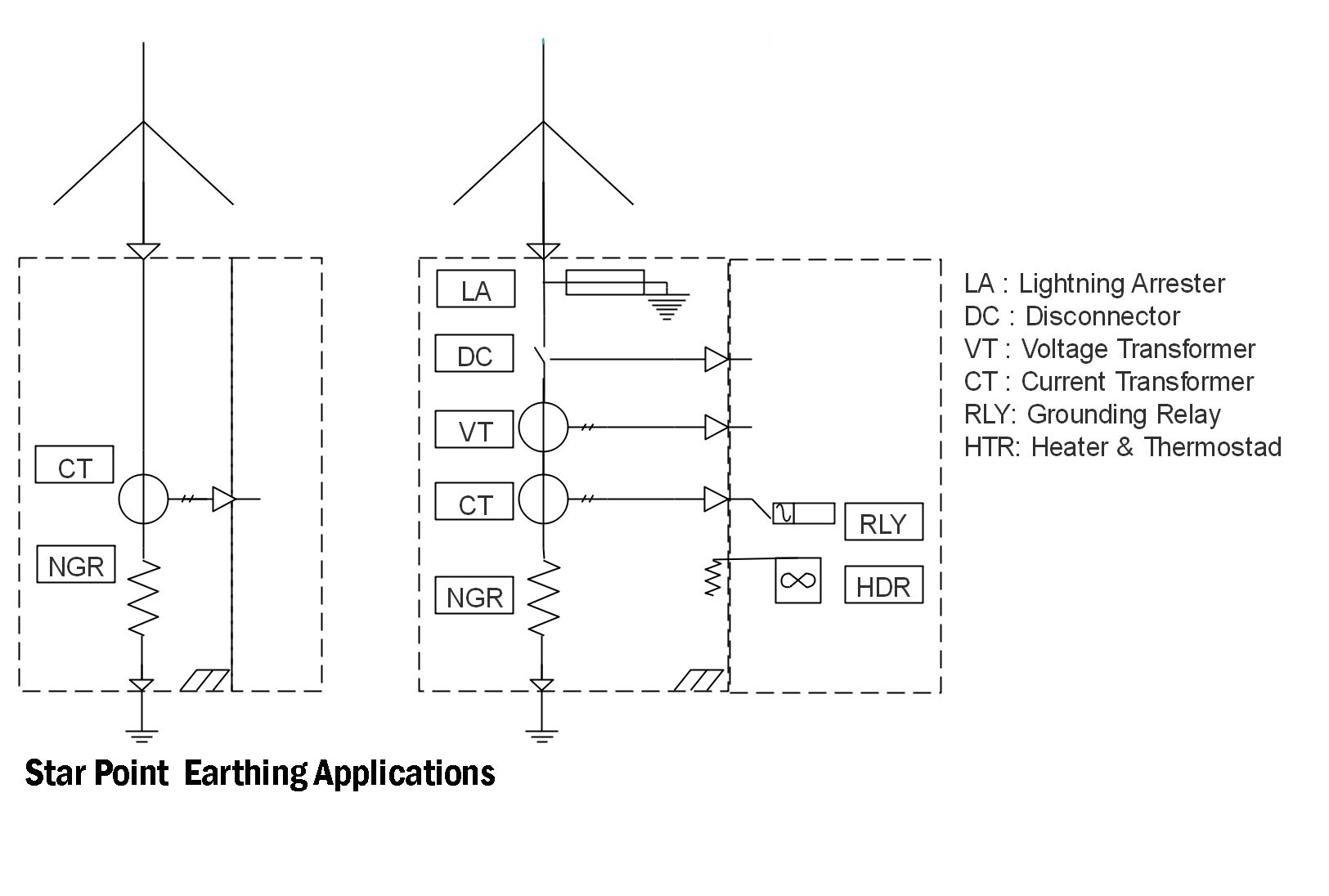
Neutral Earthing Resistor

Green Data Center Design and Management: Earthing ...

30 High Resistance Grounding System Diagram - Wiring ...
High Resistance Grounding System Diagram - General Wiring ...

High Resistance Grounding System Diagram - Diagram ...

High Resistance Grounding System Diagram - Derslatnaback

Snowy owl at the High Desert Museum

Figure 7 from Phasor diagram of a single-phase-ground ...

High Resistance Grounding System Ground Fault Detection ...
![[ZK_7592] Single Phase Transformer Wiring Diagram In ...](https://static-resources.imageservice.cloud/10612839/using-high-resistance-grounding-to-mitigate-arc-flash-hazards.jpg)
[ZK_7592] Single Phase Transformer Wiring Diagram In ...

DITEK Surge Protection - Grounding 101
High Resistance Grounding System Diagram - Free Wiring Diagram
High Resistance Grounding System Diagram - Wiring Site ...

4am start to catch the sunrise on the Jurassic Coast, Devon this morning. Wasn't expecting to see these dudes mind ✌ï¸
0 Response to "36 high resistance grounding system diagram"
Post a Comment