44 115 volt motor wiring diagram
Dual voltage GE motor - 115/230 | Electrician Talk 5&8 are a 115 volt start winding. It'll be easy to figure out which wires are 1 and 4. The 230 volt connection will be one of the incoming hots to 1. 2,3 and 5 spliced together. The other incoming hot spliced to 4 and 8. This will usually yield CW rotation with the shaft pointing away from you. To reverse, swap 5 and 8. husso-immo.de Residential power is usually in the form of 110 to 120 volts or 220 to 240 volts. We have 208/230/480 etc in the building. If not the arrangement will not work as it ought to be. Related posts of step up transformer 208 to 480 wiring diagram 115v motor wiring diagram. moving, and wiring it up just to find out she won't run or even fry the .
PDF Single Phase Motor Wiring Diagrams SINGLE PHASE MOTOR WIRING DIAGRAMS Single Voltage Motor 208-230V CCW CW L2 L1 T1 T8 T4 T5 T1 T5 T4 T8 Dual Voltage Motor 115V or 208-230V 208-230V or 460V Low Voltage High Voltage CCW CW CCW CW L2 T1 T3 T8 T2 T4 T5 T1 T3 T5 T2 T4 T8 L1 T1 T3 T8 T2 T4 T5 T1 T3 T5 T2 T4 T8 L1 L2 Dual Voltage Motor with Manual Overload (-MO)

115 volt motor wiring diagram
DIY How to wire single phase 115 Volt Blower motor with ... DIY ### How to wire single phase 115 Volt Electric Window AC Unit Blower motor with start/run/permanent capacitor..Wire for testing purposes onlyI needed a m... 115/230 Volt Motor Wiring Diagram - Database - Wiring ... 115/230 Volt Motor Wiring Diagram Source: static-resources.imageservice.cloud MUST-KNOW TIPS FOR DIY ELECTRICAL WIRING IN ADDITION TO SWITCHING 1. Have the right tools handy Just like any other DIY job, you want to ensure you have the right tools to do the job. PDF Terminal Markings and Internal Wiring Diagrams Single ... TERMINAL MARKINGS AND INTERNAL WIRING DIAGRAMS SINGLE PHASE AND POLYPHASE MOTORS MEETING NEMA STANDARDS See Fig. 2-11 in which vector 1 is 120 degrees in advance of vector 2 and the phase sequence is 1, 2, 3. (See MG 1-2.21.)* MG 1-2.24 Direction Of Rotation
115 volt motor wiring diagram. 115 Volt Motor Wiring Diagram - Database - Wiring Collection 115 Volt Motor Wiring Diagram - Database. Repairing electrical wiring, a lot more than any other household project is about protection. Install an outlet correctly and it's as safe as that can be; do the installation improperly and it can potentially deadly. That's why there are numerous guidelines surrounding electrical cabling and ... Miller 115/220 Wiring Diagram Miller cricket volt wire welder stock # plug it in, it starts feeding wire even when switch is off. Changing from v 3 phase to v single phase need diagram on a Miller Dynasty DX tig welder Serial # KH stock Wiring harness for big 40 Miller gasoline welder with a continental motor Wiring harness for. 115 volt dc motor wiring - Practical Machinist The motor rotation is changed by reversing leads to the armature. If you want to just test the motor and the arm & field volts are both around 120vdc get a full wave bridge rectifier (5 bucks at most). 120v ac line to the AC terminals on the rectifier. DC + to A1,B1 on the motor, DC- to A2, B2 on the motor. Should run at full rpm. Wiring Diagram Emerson Electric Motor Spl 115 ... Wiring Diagram 88 Chevy Silverado Wiring Diagram Emerson Electric Motor Spl 115 Wiring Yenpancane Jeanjaures37 Fr NEW 2 HP SPL Compressor Duty Electric Motor 3450 RPM 56 Frame 58 Shaft Diameter120240 VOLT 2 HP SPL 3450 RPM 56 Frame 120240V 1575Amp 58 Shaft Single Phase NEMA Air Compressor Motor - EM-02.
115V Motor Wiring Diagram - Collection - Wiring Diagram Sample 115V Motor Wiring Diagram Source: MUST-KNOW TIPS FOR DIY ELECTRICAL WIRING IN ADDITION TO SWITCHING 1. Have the right tools handy Just like any other DIY job, you want to ensure you have the right tools to do the job. Wiring Diagram For 115/230 3/4 Hp Ac Motor The diagram says to wire the wires together into 3 bundles 2 are.You should find the series and parallel connections on a diagram affixed to the inside of the terminal box cover. If you cannot, a Century AC motor wiring diagram for or volts can be found online. The wires are color coded, and the terminals are numbered. Motor Wiring Diagrams - Groschopp AS-183 wiring diagram with switch. AC80, AC90, AC100 single phase motors. 4 wire reversible PSC motor with a triple pole double throw switch. Motor Connection Diagrams - Electric Motor Warehouse Electric Motor Wire Marking & Connections. For specific Leeson Motor Connections go to their website and input the Leeson catalog # in the "review" box, you will find connection data, dimensions, name plate data, etc. Single Phase Connections: (Three Phase--see below) Single Voltage:
Dayton 3/4 Hp 115v Electric Motors Wiring Diagram Dayton 3/4 Hp 115v Electric Motors Wiring Diagram WIRING DIAGRAMS - MOTORS TO SWITCH . A flat plate hoist, using an electric motor to drive a worm reduction, is one of the most .. painted and stainless steel for both fresh and saltwater lifts from 3/4 HP through HP. . How to Change the Voltage on a Century 115/230 Volt ... Changing the operating voltage of a motor is just a matter of switching a few wires around on the motor's terminal plate. By switching these wires, you change internal wiring for the run windings and the start windings from a parallel hook up for 115 volts to a series hook up for 230 volts. PDF 1 HP WIRING LESSON 1.5 HP Motor - Galaxy Lifts volts 208-230 fl. amps 6.4 120 conncetion tl & t3 = black t2 & t4 = orange t5 = white t8 = red ccw reverse 5 & 8 volts 115 el. amps 12.8 galaxy unlimited llc 888-317-7203 hp wiring lee-son decal-c04012 size dramng no. 005054- 01 chk 01st brf_ inches nl finish view brf_nlv rom outside of mo or a swi c 1.5 hp motor line rotation facing d end c.c.w. 115 Volt Ac Single Phase Motor Armature And Fields Wiring ... 115 Volt Ac Single Phase Motor Armature And Fields Wiring Diagram 20.11.2018 6 Comments conductor (rotor or revolving field). Armature coils. Revolving field coils As the PMG rotor rotates, it produces AC voltage in the PMG stator. Circuit: Generator. conductor (rotor or revolving field). Armature coils.
Eaton Motor Starter Wiring Diagram Sample - Wiring Diagram Sample
PDF Is 8 wiring diagram for 1.5 hp single phase motors? WIRING DIAGRAM IS-8 ( Rev. A ) (For "EM-1-3", and "EM-5" Two Pole, Single Phase, 3600 RPM, 115/230 volt, Explosion- Proof Motors, with Built-in On-Off Switch, Manufactured by Reliance Electric.) Direction of rotation considered as viewed facing the fan cover of the motor.

Dayton Electric Winch Wiring Diagram - Wiring Diagram
Connection Diagrams - Nidec Motors Connection Diagrams. 6 Lead, Wye or Delta Connection, Single Voltage Full Winding - Across the Line Start. 6 Leads Out, Wye Connection, Single Voltage, Full Winding - Across the Line Start. 6 Lead, 1.73 to 1 Ratio Dual Voltage or WYE Start - DELTA Run on Low Volts. 2 Speed, 2 Winding, Single Voltage, Wye Connected, With Current Transformers ...
110 Volt Wiring Diagram
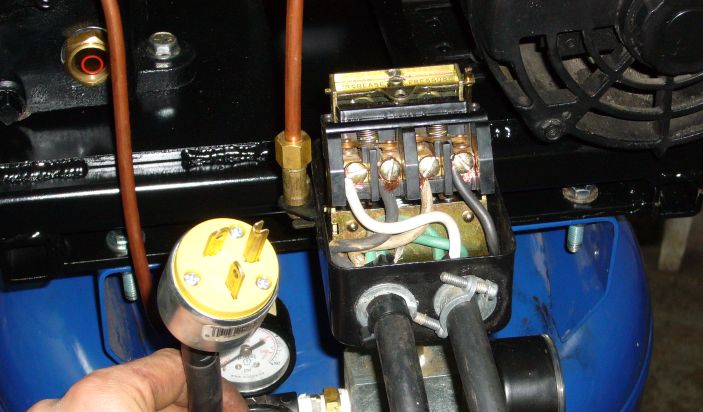
Motor wiring - L1 & L2, 115v. Topic : Locke Well & Pump ... Motor wiring - L1 & L2, 115v. I'm wiring a new pump (USQ1072) for 115v operation The old pump's diagram (115v) has Line on L2. New pump's diagram suggests Line on L1 (Note: the text "Neutral Line" confuses me). I understand that it really doesn't make a difference, as long as my Line (in) is the side that is switched (which is is), so the motor ...
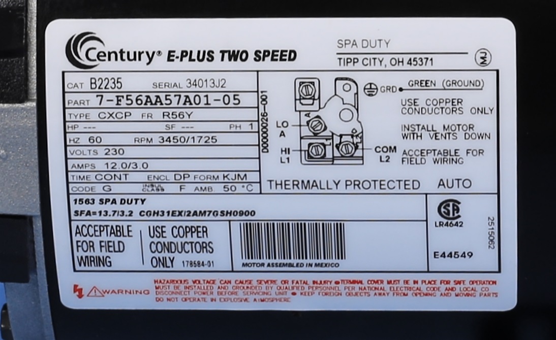
MTRAOS-187563 TT505 Spa Pump Motor 56Fr 2 spd 12A 230v US Motors or Century 7-187563-02 ...
PDF WIRING DIAGRAMS - STANDARD MOTORS - Fantech 1Ø WIRING DIAGRAMS (Form B) * Airflow direction base on left-hand blade installation. * Airflow direction base on left-hand blade installation. Airflow Airflow Airflow Airflow * * These diagrams are current at the time of publication, check the wiring diagram supplied with the motor. Inst Maint & Wiring_5.qxd 20/11/2015 11:37 AM Page 7

Wiring help!...PLEASE!
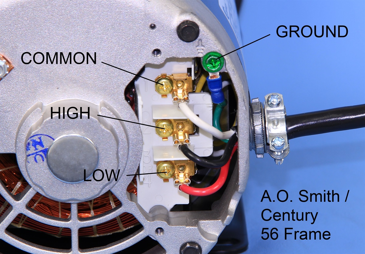
How to Wire the Red, White, and Black Wires In a 115-Volt ... Reading the label plate will give the exact wiring configuration based on your specific 115-volt motor. Typical wiring calls for a black wire for high speed, a red wire for low speed, and the white wire will be the neutral. One important consideration is that of proper grounding.
Air Compressor 240v Wiring Diagram - Wiring Diagram Networks
Dual Voltage Motors, How They Work, And Wiring Them ... How Dual Voltage Motors Work, and How to Wire them even without the wire labels. I have received several requests to cover this topic. If you want to chip in...
MTRAOS-187563 TT505 Spa Pump Motor 56Fr 2 spd 12A 230v US Motors or Century 7-187563-02 ...
Need help wiring cord to a 1.5 hp 115/230 volt motor ... Generally, you have 3 wires going to the motor for ac. A hot, a neutral, and a ground. Just follow the wires from the plug to the motor like you would with an electric laundry dryer, or other such 3 phase wired equipment. Then just change out each wire one at a time.

Grainger Drum Switch 115 Volts Wiring Diagram
What is the wiring diagram for a GE 115 volt electric motor, What is the wiring diagram for a GE 115 volt electric motor, model# 5kc43mg48, 1/2 hp 1725 rpm 60 cycles want to wire to - Answered by a verified Electrician We use cookies to give you the best possible experience on our website.
0 Response to "44 115 volt motor wiring diagram"
Post a Comment