41 automatic vent damper wiring diagram
Refrigerator Parts: Fast Shipping - Frigidaire Appliance Parts Refrigerator Parts - Shop online or call 888-343-4948. Fast shipping. Open 7 days a week. 365 day return policy. PDF GAS VENT DAMPER - Field Controls UNPACKING INSTRUCTIONS 1. The Field Controls GVD Series Gas Vent Damper is packaged in a single carton containing an assembled GVD, instruction manual, and a plug. NOTE: Some OEM supplied units have the wiring harness attached. 2. Inspect for damage prior to the installation. 3. Retrofit installations require a wire harness.
PDF GAS VENT DAMPER - SupplyHouse.com GAS VENT DAMPER Model: GVD-4 through 12 Field Controls (GVD) gas vent damper was developed to reduce off cycle venting losses through boilers and draft hoods. When, the boiler is in a standby mode. Heat escapes up the chimney. The heat comes from the boiler and the condition space. To significantly reduce these losses install a Field Controls ...

Automatic vent damper wiring diagram
PDF Burnham Damper Installation Instructions - Alpine Home Air The Field Controls GVD Series Gas Vent Damper is packaged in a single carton containing an assembled GVD, instruction manual and a plug. NOTE: Some OEM supplied units have the wiring harness attached. Inspect for damage prior to the installation. Retrofit installations require a wire harness. Order the universal wire harness #46390008. Wire a Vent Damper | How To - YouTube Items used/shown in this video:Weil McLean Vent Damper Assembly: Controls Vent Damper Assembly: V... PDF Installation Instructions Caution VENT DAMPER (MUST ROTATE COUNTER CLOCKWISE). M3944 S4 NORMAL SERVICE SERVICE FUNCTION (SWITCH OR JUMPER OPTION) Fig. 4. Wiring diagram for M892 connection to L8148E1166 using wiring harness with two Molex plugs. MV MV/PV PV GND (BURNER) 24V GND 24V SPARK S8600F, H, M; S8610F,H POWER SUPPLY. PROVIDE DISCONNECT MEANS AND OVERLOAD PROTECTION AS ...
Automatic vent damper wiring diagram. Gvd-6 Wiring Diagram - schematron.org A wiring diagram is a streamlined standard photographic representation of an electrical circuit. It shows the parts of the circuit as.A Wiring Harness is a 4-wire cable, 8 feet ( meters) long, with D mating plug on one end and mating plug for S86/S/S/S or Penn Baso G60 or G66 on the other. An outlet box connector is on each end. Guide to Zone Dampers for Heating & Cooling Air Duct Controls This unit is an automatic opposed-blade duct damper. Here is a commercial automatic air supply register control which contains a booster fan as well. You can spot an automatic zone damper on duct work by noticing that there is an external motor mounted on the ducts in one or more locations. Gas Venting Dampers, GVD Models - Field Controls Field Controls gas vent dampers (GVD) are made of stainless steel and is available in 8 sizes, 4″ through 10″ and 12″. Dual safety switches allow the burner to fire only when the damper is in the open position. The GVD, gas venting damper, will not interfere with existing appliance safety controls, when properly installed. Specifications PDF AUTOMATIC VENT DAMPER - Slantfin 1. Read this installation manual, vent damper manufacturer's instructions, the "WARNING" label attached to the top of the boiler, the "WARNING" on the wiring diagram and the "DAN-GER" label on the vent damper carton. 2. Perform pre-installation inspection as required by ANSI specifi-cation Z21.66. See manufacturer's vent damper ...
Vent Damper Wiring Diagram - chatbot.euroresidentes.com vent-damper-wiring-diagram 2/3 Downloaded from chatbot.euroresidentes.com on May 18, 2022 by guest Insulate with batts, sheet, tubing covers, and foam Work with solid-state controls Understand electrical and electronic symbols used in schematics Voluntary industrial standards, 1976 United States. Congress. Senate. Committee on the Judiciary. How to bypass Blocked Vent Switch? - DoItYourself.com ... I have my Effikal Vent Damper set to "Hold Open" and the Burnham Series 2 will not fire up. I assume this is due to the Blocked Vent Switch being faulty but I want to make sure it is just that and not anything else before ordering parts. Thanks in advance for any help! JohnnyO Photo and image hosting, free photo galleries, photo editing Chapter 30 Elevators and Conveying Systems - UpCodes The diagram on such sign may be omitted provided that signs containing such diagram are posted in conspicuous places on the respective floor. In such case, the sign at the elevator landing shall be at least 2 1 / 2 inches by 10 inches (64 mm by 254 mm) and the diagram signs shall be at least 8 inches by 12 inches (203 mm by 305 mm). 24 Vac Motorized Damper Wiring Diagram - schematron.org MOTOR TERMINALS. 1. Trim 1/4" off the end of the Air Flow by jumping terminal W and Y and then wiring. to damper terminal #4. Wire R on the thermostat to 24 VAC between Terminal 1 and 3 when damper is open. End Switch - maximum load rating - 2 amps. (usage optional) TRANSFORMER.
PDF Automatic Make-up Air Damper With Transformer & Pressure ... MULTIPLE DAMPERS More than one damper may be required to balance the system. If more than one is required use (1) MD6TU or MD8TU and then use the MD6 or MD8 dampers as ad-ditional dampers. INSTALLATION OF PRESSURE SWITCH AND PROBE For the probe & pressure switch to work effectively the roof or wall cap must have a spring loaded damper. Q35 Series Automatic Vent Damper System Technical Bulletin Figure 1: Q35 Automatic Vent Damper System The Q35 energy-saving, high-efficiency, automatic vent damper system retains heat that is normally wasted through the open flue when the appliance is not firing. The Q35 consists of a Y15 damper, M35 actuator, and Y84 wiring harness. The damper section is available in sizes from Damper Wiring Diagram - banca-movil.euroresidentes.com get those all. We offer Damper Wiring Diagram and numerous ebook collections from fictions to scientific research in any way. accompanied by them is this Damper Wiring Diagram that can be your partner. Safety Investigation of Gas Appliance Energy Saving Devices and Automatic Vent Dampers for Oil Furnaces D. E. Adams 1977 Indiana Register 1987 Creative SBS 370 Speakers Repaired For No Power 16.04.2022 · This one is same speaker which was modified earlier by me by installing Bluetooth Kit. Customer sent me complaining no power. On arrival I checked the adapter it uses 11.4V AC tested using multimeter voltage is OK. Now for further inspection I opened the unit. I am shocked Creative SBS 370 Speakers Repaired For No Power By Yogesh From India
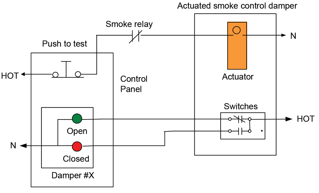
Fire Smoke Damper Wiring Diagram Collection
Damper Diagram Wiring - consbi.comuni.fvg.it See wiring diagram Automatic Vent Damper Wiring Diagram AOBD damper wiring (single) 350z Fans Not Working Terminal 3 is the pot's output Terminal 3 is the pot's output. Automatic reports show actual and historical performance data, recommending the further potential for energy savings, predictive maintenance It reveals the components of the ...

Hvac Damper Wiring | schematic and wiring diagram
Vent Damper Wiring Diagram vent-damper-wiring-diagram 1/1 Downloaded from zee.kentamplinvocalacademy.com on May 16, 2022 by guest Vent Damper Wiring Diagram This is likewise one of the factors by obtaining the soft documents of this Vent Damper Wiring Diagram by online.
32 Automatic Vent Damper Wiring Diagram - Wiring Diagram Database
Series Q35 MIZER Automatic Vent Damper System Technical ... The Q35 energy-saving, high-efficiency, automatic vent damper system retains heat that is normally wasted through the open flue when the appliance is not firing. The Q35 consists of a Y15 damper, M35 actuator, and Y84 wiring harness. The damper section is available in sizes from 102 mm (4 in.) through 305 mm (12 in.) nominal duct diameter.
Automatic Damper Wiring Diagram - Wiring Diagram Schema
View Products By Publication: LOREN COOK COMPANY Lab Exhaust Isolation Damper Wiring 200-480v submittal; Lab Exhaust Isolation Damper Wiring 230-575v submittal; Lab Exhaust Isolation Damper Wiring VFD 200-480v submittal; Lab Exhaust Isolation Damper Wiring VFD 230-575v submittal; Side Intake Panel - QMX submittal; Side Intake Panel - TCNHBLE submittal; VP Nozzle submittal; VPA Nozzle submittal

Wiring-Automatic Vent Damper
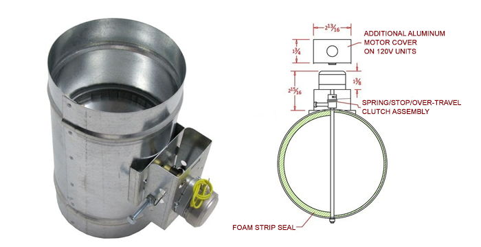
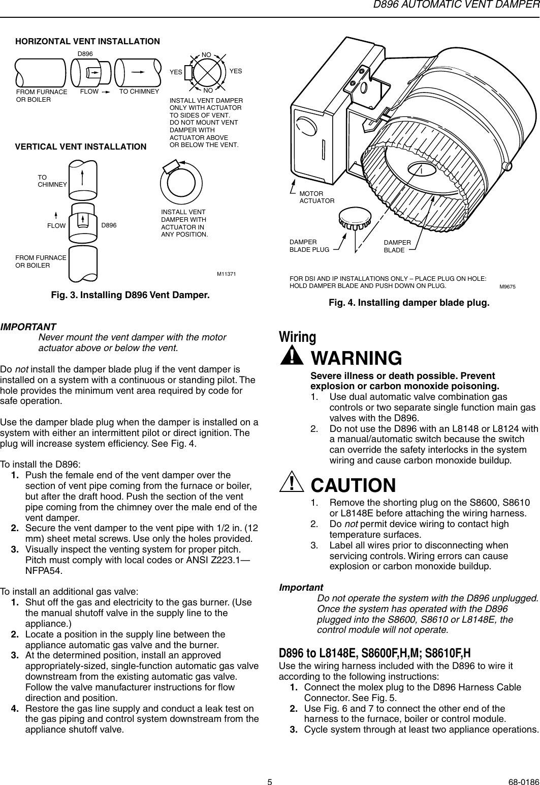
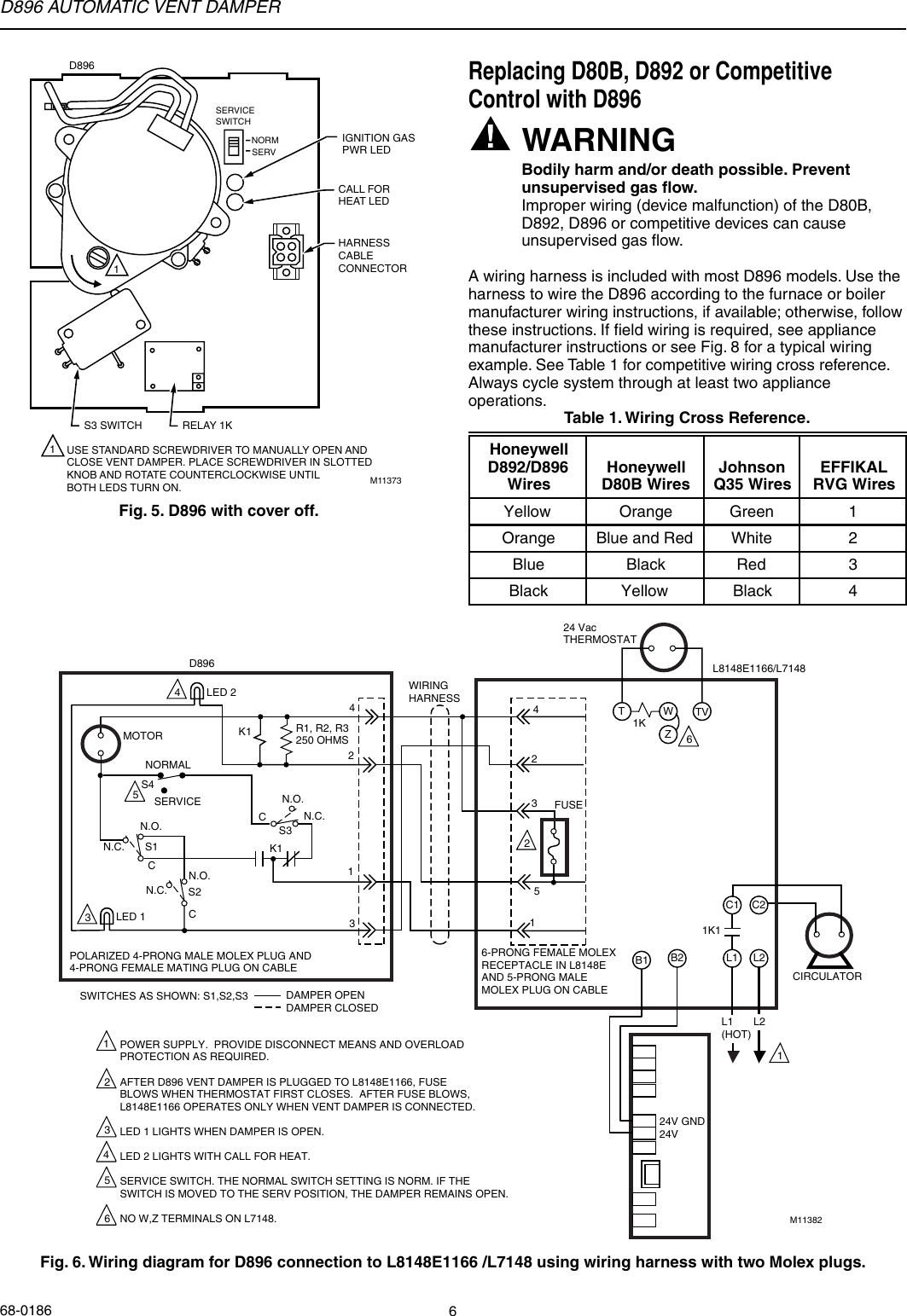
PDF 69-1088B - D896 Automatic Vent Damper - Honeywell Push the female end of the vent damper over the section of vent pipe coming from the furnace or boiler, but after the draft hood. Push the section of the vent pipe coming from the chimney over the male end of the vent damper. 2. Secure the vent damper to the vent pipe with 1/2 in. (12 mm) sheet metal screws. Use only the holes provided. 3.

Automatic Vent Damper Wiring Diagram - General Wiring Diagram
ALLDATA Cookie Notice. We use cookies to keep our products working properly, improve user experience, analyze site traffic through our analytics partners, and serve targeted communications.
Automatic Vent Damper Wiring Diagram - Free Wiring Diagram
MUAS 750 Makeup Air System - Makeup air systems - Fantech The MUAS 750 includes an 8” EC-motor fan with airflow up to 750 cfm (max), an 8” metal intake wall hood, an 8” motorized shut-off damper, an 8” filter cabinet with a pleated MERV 10 filter, an 8” duct silencer, and 3 pairs of 8” mounting clamps. Each MUAS comes equipped with a Fantech Makeup Air Controller (FMAC).

How To Install Motorized Damper : Honeywell TRUEZone® Damper System Installation - YouTube
Automatic Vent Damper Wiring Diagram Collection - Wiring ... Automatic Vent Damper Wiring Diagram Collection. automatic vent damper wiring diagram - A Novice s Overview of Circuit Diagrams A first take a look at a circuit diagram may be confusing, yet if you can read a metro map, you can review schematics. The objective coincides: receiving from point A to point B. Literally, a circuit…
Automatic Vent Damper Wiring Diagram - Wiring Diagram
Guide to Zone Dampers for Heating & Cooling Air Duct Controls Carson, Dunlop & Associates Ltd., 120 Carlton Street Suite 407, Toronto ON M5A 4K2. Tel: (416) 964-9415 1-800-268-7070 Email: info@carsondunlop.com.The firm provides professional HOME INSPECTION SERVICES and also extensive HOME INSPECTION EDUCATION and home inspection-related PUBLICATIONS.Alan Carson is a past president of ASHI, the American …
Motorized Dampers | AmericanHVACParts.com
Gas Log 101 Troubleshooting NOTE: Vent Free & Vented Variable Wall Switches Variable Wall Switches Include Rocker Switch & Battery Pack NOTE: Vent Free & Vented Vent Free Burners • Certified Heating Appliance Z21.11.2B‐2010 • Equipped with An Oxygen Depletion Sensor (ODS) • Use in Listed Solid‐Fuel Burning or Vent Free Firebox
Automatic Vent Damper Wiring Diagram - General Wiring Diagram
Flue Damper Wiring - Heating Help: The Wall If you remove the damper completely, then all you need to do is connect the blue and red. This is the boiler side of the molex. That way the 24v which powered the motor and went through all the safeties/limits will power the gas valve. If you have a picture of the wireing diagram, I can confirm 100%. Serving Northern Maine HVAC & Controls.

Hvac Damper Wiring | schematic and wiring diagram
Gas Boiler Vent Damper Troubleshooting Video - YouTube Smith from Hudson Valley Community Colleges details the entire process troubleshooting a vent damper on a gas boiler usi...

Motorized Power Damper HVAC - Normally Closed, Power Open | FAMCO
AUTOMATIC VENT DAMPER boiler, the "WARNING" on the wiring diagram and the “DAN-. GER” label on the vent damper carton. 2. Perform pre-installation inspection as required by ANSI ...
Automatic Damper Wiring Diagram - Wiring Diagram Schema
Furnaces Vent Damper Wiring Diagram - Forced Air Furnace • Check the wiring diagram for the damper and 24 VAC transformer. The Ventilation Controller operates 2.When installing the Ventilation Control on downflow furnaces, Lennox Vent Control.5 furnaces and boilers. D896 AUTOMATIC VENT DAMPER Fig. 5. Wiring diagram for D896 connection to L8148E1166 using wiring harness with two molex plugs.
Master Flow Temperature Thermostat Wiring Diagram - Wiring Diagram
Bypassing the wiring on a vent damper? - Heating Help: The ... Run the damper to the open position. It is for efficiency savings only. Once the damper is open disconnect all wiring from the damper. It will then stay open. Then you have to bypass the damper end switch wiring so the burner will run. You have to know how to do this.
0 Response to "41 automatic vent damper wiring diagram"
Post a Comment