38 autometer tach wire diagram
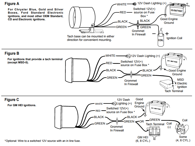
Jul 02, 2021 · Autometer tach wiring diagram. For chrysler blue gold and silver. The wiring diagram shown is a typical installation. Figure a figure c. A wiring diagram is a simplified traditional pictorial depiction of an electrical circuit. The tach must be returned to autometer for a light replacement. Toll free tech support. INSTALLATION INSTRUCTIONS. 5" Tachometer. Part Number. P5155500. P5155975. INTRODUCTION. • Any Auto Meter Shift-Lite™, or Quick-Lite™ Shift-Lite can be used ...3 pages
Buy Auto Meter Autogage Tachometer: Tachometers - wiringall.com FREE 4 simple wires needed for operation, Power, Ground, Light source from a . Installation of the Autogage Tachometer was fairly simple with only minor wiring including a wire to the distributor, a good ground, a 12 volt switched power.

Autometer tach wire diagram
INSTALLATION INSTRUCTIONS. Elite Street Tach. 2650-1455-00 Rev. A. Wiring. The wires are connected as follows: • Black - Engine Ground.3 pages INSTALLATION INSTRUCTIONS. ®. Instr. No. 2650-444D. IMPORTANT. This tachometer is factory calibrated to operate on 8 cylinder engines. For 4 or 6.2 pages The wiring diagram shown is a typical installation. Autometer gps speedometer wiring diagram auto meter diesel tach wiring diagram wire center u2022 rh. As stated earlier the lines in a Autometer Tach Wiring Diagram represents wires. Autometer Tachometer Wiring Diagram wiring diagram is a simplified gratifying pictorial representation of an ...
Autometer tach wire diagram. Nov 19, 2020 · Auto Gauge Tach Wiring – Wiring Diagram Data – Autometer Gauge Wiring Diagram Wiring Diagram consists of numerous in depth illustrations that show the connection of varied items. It contains directions and diagrams for various varieties of wiring strategies along with other things like lights, windows, etc. Prior to installation of your tachometer, check with the ignition box manufacturer for recommended tachometer signal location. WARNING. Do NoT USE THiS PRoDUCT ...3 pages Autometer Tach Wiring Diagram. Variety of autometer tach wiring diagram. A wiring diagram is a streamlined standard pictorial representation of an electrical circuit. It reveals the components of the circuit as simplified shapes, and also the power and also signal connections in between the devices. A wiring diagram usually gives info about the relative… Autometer Basic Tach Installation Wiring Instructions Tutorial How-To http://www.jegs.com/webapp/wcs/stores/servlet/KeywordSearchCmd?manufacturer=Auto%20Mete...
Autometer Tach Wiring Diagram Gallery April 14, 2018 by headcontrolsystem Variety of autometer tach wiring diagram. A wiring diagram is a simplified conventional photographic representation of an electric circuit. It reveals the elements of the circuit as simplified shapes, as well as the power and signal links in between the devices. Gauges. Autometer volt gauge wiring diagram how to install auto meter voltmeter mad with boat gauges instrumenteters classic style 60 160 vdc the hull truth boating cobalt air fuel ratio 3 ways a car amp electric monitor installation voltage instructions dimmer switch in direct fit 2 1 16 8 18v core wire on an tach images ford ranger tachometer electrical network short sweep panel 600a ammeter ... autometer tach wiring diagram - thanks for visiting my internet site, this message will go over regarding autometer tach wiring diagram. We have collected several images, hopefully this picture is useful for you, and aid you in finding the solution you are searching for. Description : How To Install An Auto Meter Tach by IDS Mount · 2006 · Cited by 2 — INSTALLATION INSTRUCTIONS. 2650-1141 ... You may also email us at service@autometer.com. ... Insert tachometer hook-up wires through the shock mounting to.2 pages
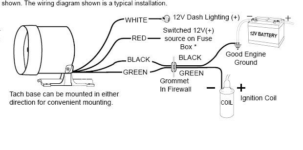
Replace the screw. W iring Connect the tachometer wires as shown. The wiring diagram shown is a typical installation.2 pages Wiring your new Autometer tachometer into your car will complete the installation. Once you have selected a mounting location, you can run the four wires that operate the tachometer. The tachometer is designed to show the engine RPMs or rotations per minute. Autometer has designed their tach to be used with four, six ... order Auto Meter 3219 or GE 86 bulb. Turn socket 1/8 turn counter-clockwise to remove. 1. Turn on the power to the tach by turning the key on (Do Not start the engine). Set the desired RPM by turning the adjust knob on the tach; the pointer will move. Stop when it reaches the desired shift point. 2. Turn the power off. The tach will now use the Autometer Phantom Tach Wiring Diagram - wiring diagram is a simplified satisfactory pictorial representation of an electrical circuit. It shows the components of the circuit as simplified shapes, and the facility and signal connections along with the devices.
white and yellow ice cream with cone
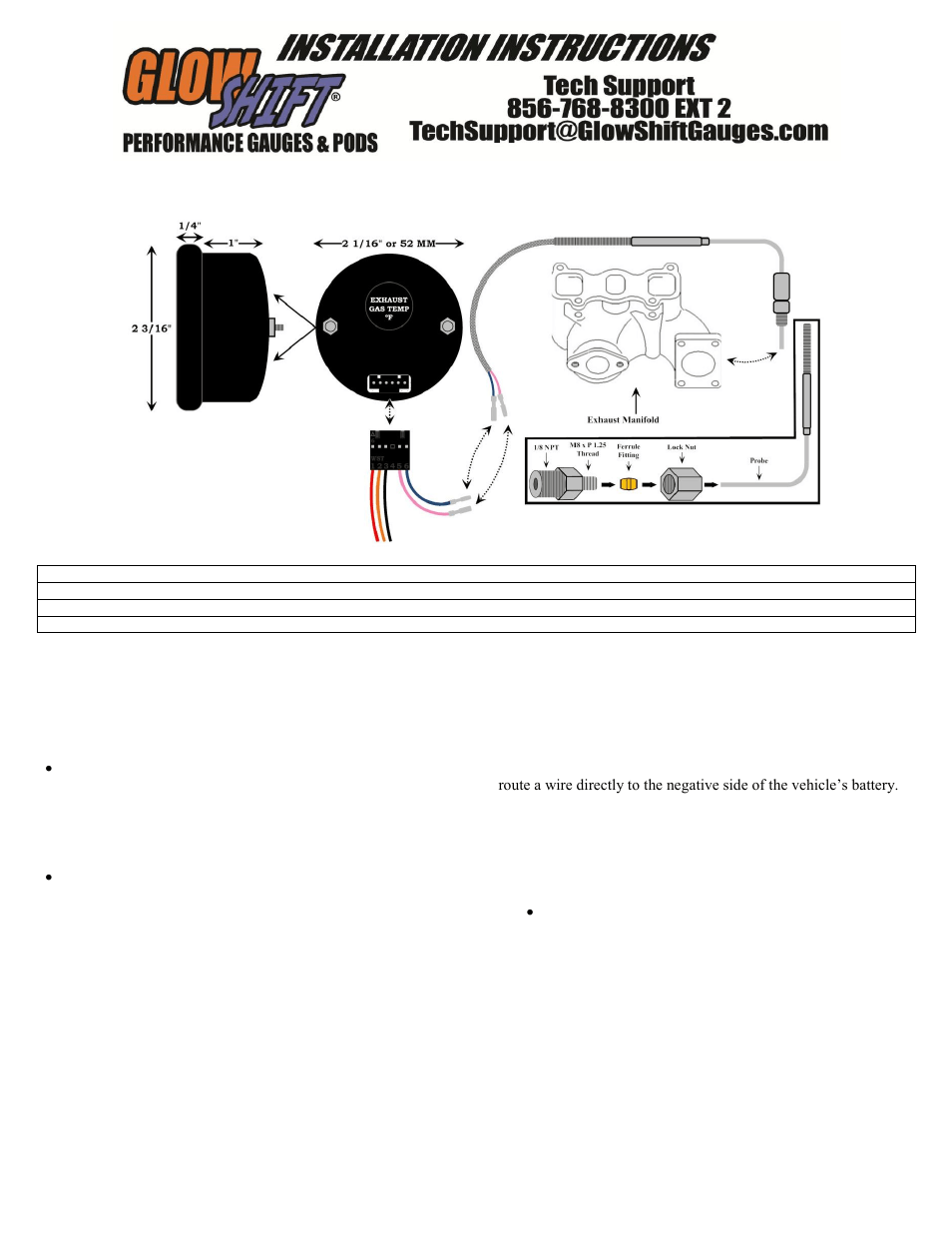
For turbo engines, install the probe inches from the turbo exhaust outlet or . a hole in the dash, a gauge panel or an Auto Meter Gauge Pod.Sep 30, · Need help wiring Autometer electric gauges Posted by blcknspo0ln, Sep 17, Sep 17, #1. blcknspo0ln The actual diagram can be found in the DSM manual or something like a Haynes manual.

Autometer Sport Comp Wiring Diagram | Free Wiring Diagram
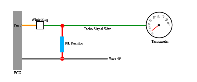
The yellow wire from our tachometer can receive signal from the ecu by following the diagram in fig 4. Diagram a vdo tachometer with hourmeter is programmable from 5 to 200 pulses per revolution vdo vdo item description quantity 1. Variety of autometer tach wiring diagram. Set the cylinder switches to match the number of cylinders in your ...
How to Install an Auto Meter Sport Comp 5in Tachometer w ...
The tachometer is designed to show the engine RPMs or rotations per minute. Autometer Sport Comp Tachometer Wiring Diagram pro p tach wiring diagram maipinineh pro p tach wiring diagram operates on 4 6 or 8 cylinder engines with points electronic and most 12v high performance racing ignitions pro p tach chart.
Ford Ranger Tachometer Install
Wiring Connect the tachometer wires as shown. The wiring diagram shown is a typical installation. ... diagram illustration on the right. 4 Cyl.- Both switches down 6 Cyl.- Switch #1 down. Switch #2 up ... gage model 2302 tachometer when used with Auto Meter Model 5215 BEI/Laser Adapter. Laser II with date code of 8100 or higher
Autometer Egt Gauge Wiring
AutoMeter's gauges are only as good as the installation. Make sure your gauge is Find product manuals and wiring diagrams for your Auto Meter product.AutoMeter Pro comp gauges, pro comp gauges, pro comp. Thank you for your purchase of the Digital Pro Shift System (DPSS) from Auto Meter Products, Inc.

SS Tach Signal Conversion for LSX ECM Setup - Chevelle Tech
As stated earlier, the lines at a Autometer Tach Wiring Diagram represents wires. Sometimes, the wires will cross. However, it does not imply link between the wires. Injunction of 2 wires is generally indicated by black dot at the junction of two lines. There'll be primary lines which are represented by L1, L2, L3, and so on.
Autometer Gauge Wiring Diagram | Wiring Diagram
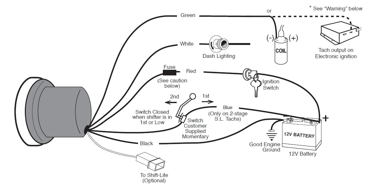
The tachometers in the diagram use a specific Auto Meter wiring color code, so if you've got a different brand of tachometer you should reference its own schematic. (Image/Auto Meter) Of course, this cheat sheet only covers the tachometer's needle movement.

Wiring Up A 5'' Monster Tacho In Your Car - Car Electrical ...
Autometer Sport Comp Tachometer Wiring Diagram pro p tach wiring diagram maipinineh pro p tach wiring diagram operates on 4 6 or 8 cylinder engines with points electronic and most 12v high performance racing ignitions pro p tach chart.

19 Beautiful Autogage Tachometer Wiring Diagram
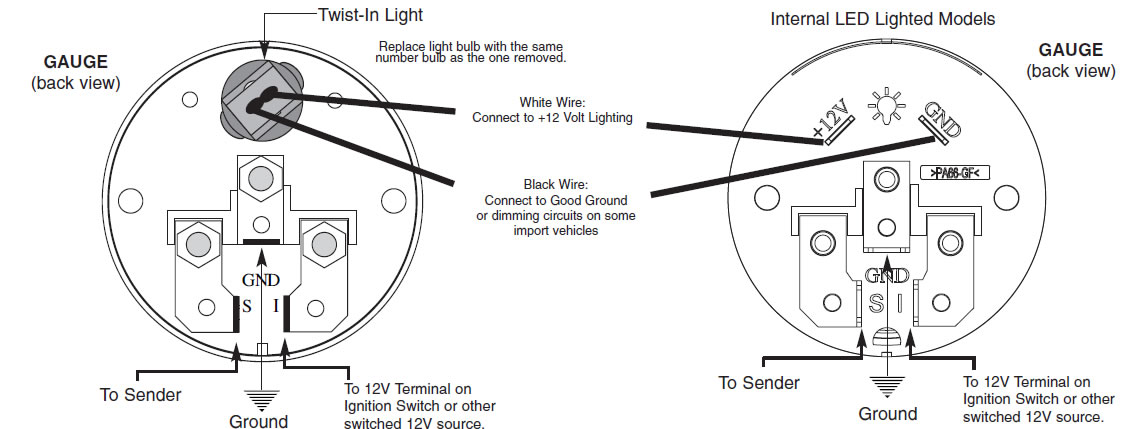
May 7, 2020 — Red = key on power supply · Black = common chassis ground · White = dash lighting power · Yellow = used only on Internal Coil Magneto tachometers ...

Autometer Tach Troubleshooting
Please download these autometer tach wiring diagram by using the download button, or right select selected image, then use Save Image menu. Wiring diagrams help technicians to determine the way the controls are wired to the system. Many people can read and understand schematics generally known as label or line diagrams.

Autometer Tach Wiring Diagram | Free Wiring Diagram
If after completely reading these instructions you have questions regarding the operation or installation of your instrument(s), please contact Auto Meter ...4 pages

Auto Meter Tach Wiring Diagram Wires | schematic and ...
Wiring Connect the tachometer wires as shown. The tach must be returned to AutoMeter for a light replacement. The wiring diagram shown is a typical installation. The tachometer is designed to show the engine RPMs or rotations per minute. Figure A Figure C. This tachometer is factory calibrated for 8 cylinder engines.

Autometer Sport Comp Tach Wiring
2 5/8" Electric Speedometer, 3 wire with green signal wire. 2-5/8" Electric Speedometer, 4-wire with purple signal wire. 3 3/4" & 5" Electronic Speedometer. Tach/Speedo Combo.
Autometer Tachometer Wiring Diagram Collection
while FoR SERViCE SEND To: AUTO METER PRODUCTS, INC. 413 W. Elm St., Sycamore, iL 60178 USA (866) 248-6357 Email us at service@autometer.com 2650-1244-00 Rev. B 3/30/09 SERVICE For service send your product to Auto Meter Products, inc. in a well packed shipping carton.

Tachometer Wiring Diagram - Wiring Diagram And Schematic ...
Replace the cup back onto the tach with mounting bracket located at the bottom while making sure the wires are clear of the screw hole, then reinstall the screw. Wiring the Tachometer. Connect the tachometer wires as shown in the wiring diagrams below, which are typical installations.

Autometer Temp Gauge Wiring Diagram - Wiring Diagram And ...
Autometer Sport Comp Tach Wiring. Engine Cylinder Adjustments. This tachometer is factory calibrated for 8 cylinder engines. Wiring Connect the tachometer wires as shown. The wiring diagram. Wiring your new Autometer tachometer into your car will complete the installation. Once you have selected a mounting location, you can run the four wires that.

Autometer C2 Tach Wiring Diagram - 30
As stated earlier, the lines in a Autometer Tach Wiring Diagram represents wires. At times, the wires will cross. However, it does not imply connection between the wires. Injunction of two wires is usually indicated by black dot on the junction of 2 lines.
Autometer Sport Comp Tachometer Wiring Diagram For Your Needs
Autometer Tachometer Wiring Diagram. How to install a tachometer onallcylinders 5 pro comp stock tach wiring installation instructions manualzz auto meter 6858 elite street smithsclassic autometer and msd ignition factory five racing forum ford ranger 9117 adapter jegs 2893 user manual 1 page also for 2891 2892 2890 hands on effective data ...

Autometer Sport Comp Wiring Diagram | Free Wiring Diagram
TACHOMETER For use on standard and most electronic ignitions MODELS 3904, 3905, 3911, 4299, 4899, 5699, 5899 ... Crane connect wire to tach terminal. COIL Tach Terminal TM ... Auto Meter Products, Inc. warrants to the consumer that all Auto Meter High Performance products will be free from defects in material and workmanship for a period of ...
Autometer Pyrometer Wiring Diagram
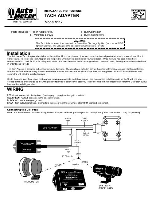
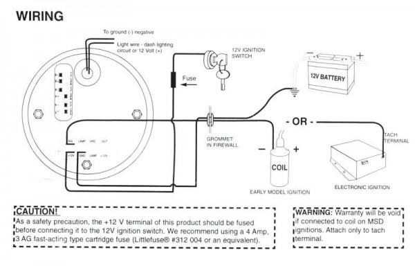
to installation of your tachometer, check with the ignition box manufacturer for recommended tachometer signal location. CAUTION!!! As a safety precaution, ...2 pages
How to Install an Auto Meter Pro-Comp Ultra-Lite Voltmeter ...
Autometer Sport Comp Tach Wiring Diagram. As a safety precaution the RED wire of this product should be fused before connecting it to the positive (+) side of switched power source. We recommend using. Any Auto Meter Shift-Lite™, or Quick-Lite™ Shift-Lite can be used with tachs 2) Pass tach wires through shock strap assembly and slide tach ...
Autometer Phantom Tach Wiring Diagram - 14
Jun 04, 2020 · Autometer Tachometer Wiring Diagram – wiring diagram is a simplified gratifying pictorial representation of an electrical circuit. It shows the components of the circuit as simplified shapes, and the aptitude and signal connections between the devices. A wiring diagram usually gives guidance virtually the relative slant and settlement of ...

brown flip phone on brown wooden table
The wiring diagram shown is a typical installation. Autometer gps speedometer wiring diagram auto meter diesel tach wiring diagram wire center u2022 rh. As stated earlier the lines in a Autometer Tach Wiring Diagram represents wires. Autometer Tachometer Wiring Diagram wiring diagram is a simplified gratifying pictorial representation of an ...

gray concrete statue of a man
INSTALLATION INSTRUCTIONS. ®. Instr. No. 2650-444D. IMPORTANT. This tachometer is factory calibrated to operate on 8 cylinder engines. For 4 or 6.2 pages
How to Install a Tachometer - OnAllCylinders
INSTALLATION INSTRUCTIONS. Elite Street Tach. 2650-1455-00 Rev. A. Wiring. The wires are connected as follows: • Black - Engine Ground.3 pages
Autometer Pro Comp Tach Wiring Diagram Collection

Autometer Autogage Tach Wiring Diagram - Wiring Schema

Auto Gauge Wiring Diagram Tachometer Database

blue and green thread on brown wooden shelf
msd 8360 tach use? - Chevelle Tech

Wiring Diagram For Autometer Gauges
Autogage Tach Wiring

Autometer Sport Comp 2 Wiring Diagram - Wiring Diagram and ...

Tachometer Wiring - Complete Wiring Schemas

8 Gauge Wire Relay Simple Tachometer Wiring Diagram ...

Ford Ranger Tachometer Install : The Ranger Station

21 New Glowshift Boost Gauge Wiring Diagram
Autometer Phantom Tach Wiring Diagram
0 Response to "38 autometer tach wire diagram"
Post a Comment