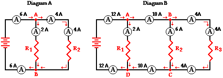
42 where is the resistor located on this diagram
› kb › articlesUnderstanding Battery Configurations | Battery Stuff Jan 24, 2016 · One stationary (12v/140ah) and one portable (12v/25ah). I want to be able to plug portable bank into stationary bank for charging. Should I be concerned about the inrush current when connecting portable bank into stationary bank while battery charges are equalizing. Can a resistor be added to cable to slow current while banks are equalizing. Understanding Battery Configurations | Battery Stuff Jan 24, 2016 · In the diagram above, we have a battery bank that produces 12 volts and has 20 amp hours. Don't get lost now. Remember, electricity flows through a parallel connection just the same as it does in a single battery. It can't tell the difference. ... Can a resistor be added to cable to slow current while banks are equalizing. If so where in ...
Dodge Dakota,Durango Blower Motor Resistor Wiring Diagram Wiring diagram for 2001 Dakota and Durango Blower Motor Resistor. With this kit available from Napa/Dorman, make sure to use the proper crimping tool that cr...

Where is the resistor located on this diagram
How the Ballast Resistor Works - YouTube This Video explains how the Ballast Resistor Works.For additional How-to Tutorials Visit our Website: 9.06 Unit Test: Electricity Flashcards | Quizlet Mechanical energy is converted to electrical energy. Which statement best describes magnetic fields? Magnetic fields are always found in insulators. Magnetic fields have north and south magnetic poles. Magnetic fields need a conductor. Magnetic fields must have only positive charges. Magnetic fields have north and south magnetic poles. Why does the location of the resistor matter in this circuit wolowizard: In my understanding, the actual location of a resistor in a serial circuit does not matter. Correct. wolowizard: So why do I get an alert in the second circuit, as shown in Img 2, but not in the first one (Img 1) ? The resistor in the second circuit is not connected to the circuit. It's two pins are also shorted together in row 19.
Where is the resistor located on this diagram. › glossary › blower-motor-resistorBlower motor, resistor: how it works, symptoms, problems, testing Aug 01, 2021 · In the 2008-2011 Ford F150, the blower motor resistor is also located behind the glove box, but is installed on the right side of the plastic air duct. This thread at f150online.com shows where the resistor is located. The author of this blog shared his experience of replacing the blower motor resistor in Jeep Liberty. In some older cars and ... › en › productsElectronic Components and Parts Search | DigiKey Electronics Co-Browse. By using the Co-Browse feature, you are agreeing to allow a support representative from Digi-Key to view your browser remotely. When the Co-Browse window opens, give the session ID that is located in the toolbar to the representative. Strains Mushroom Psychoactive Sep 17, 2022 · Search: Psychoactive Mushroom Strains. The famous types of psychedelic mushrooms, including, Psilocybe semilanceata, Psilocybe cubensis, Psilocybe baeocystis, Psilocybe tampanensis, etc There are many varieties of magic mushrooms that can take people on a mind-altering trip 6 milligrams per gram of dried mushroom THC-rich strains may be …
Resistor Circuit Diagrams: Understanding Connections and ... - WellPCB In the diagram below, we have a simple circuit with a series of connections of resistors. The first resistor has a resistance value of R1, and the second resistor has R2. According to Ohm's Law; V=IR V = I * R_t Where R_t here is our effective resistance of resistors connected in the circuit. en.wikipedia.org › wiki › Electrical_networkElectrical network - Wikipedia The effective resistance and current distribution properties of arbitrary resistor networks can be modeled in terms of their graph measures and geometrical properties. A network that contains active electronic components is known as an electronic circuit. Such networks are generally nonlinear and require more complex design and analysis tools. Simple Series Circuits | Series And Parallel Circuits | Electronics ... This printout is telling us the battery voltage is 9 volts, and the voltage drops across R 1, R 2, and R 3 are 1.5 volts, 5 volts, and 2.5 volts, respectively. Voltage drops across any component in SPICE are referenced by the node numbers the component lies between, so v(1,2) is referencing the voltage between nodes 1 and 2 in the circuit, which are the points between which R 1 is … resistor wire location | Ford Mustang Forum The resistor wire is a short section of the wire only, not the whole thing. If you follow the pink wire from the ignition switch the resistor area would be several inches from the ignition switch. The wire would be thicker in that area that is the resistor. You will have to unwrap the harness a bit to get to it.
Where is the resistor located on the diagram? - Brainly.com INSTRUCTION: Refer your TWO answers in diagram/picture above with explanation please >Which combination of elements would likely form a covalent bo … nds? a. W and Y b. Y and Z c. V and W d. X and Y >Which combination of elements would likely form a covalent bonds? a. V and Z b. Z and W c. V and Y d. Y and X#Nonsense=Report Resistor Located On This Diagram Where Is The Resistor Located On The Diagram Brainly Com. Part 1 Blower Motor Circuit Diagram 1991 1995 3 9l Dodge. Toyota Rav4 Service Manual Blower Motor Circuit. Building Simple Resistor Circuits Series And Parallel. 2006 Chevy Silverado Blower Motor Resistor Wiring Diagram. EOF Diagram of where the resistor is located i've looked..fire wall Diagram of where the resistor is located i've looked..fire wall - Answered by a verified Ford Mechanic. We use cookies to give you the best possible experience on our website. By continuing to use this site you consent to the use of cookies on your device as described in our cookie policy unless you have disabled them.
Schematic diagram of the second-order resistor-capacitor (RC ...
Blower motor, resistor: how it works, symptoms, problems, … Aug 01, 2021 · In the 2008-2011 Ford Escape, the resistor is located behind the glove box on top of the HVAC unit air duct. It's held by two screws and is easy to replace. See the photo. ... This diagram shows how the blower motor resistor is connected in a typical car. In this car, in the highest "4" fan speed setting, the resistor is bypassed and the blower ...
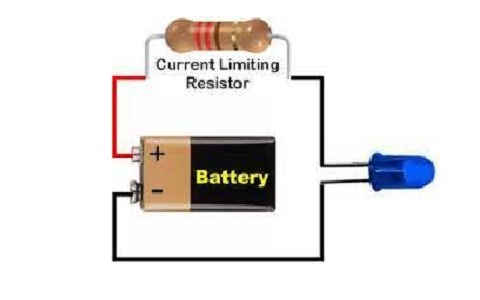
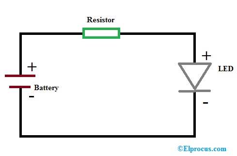
LED Resistor : Circuit Diagram, Working and Example Problems
Kenworth W900 A/C wiring diagram - MHH AUTO - Page 1 Jul 15, 2015 · It's located on the bottom row of the fuse box, on the right-hand side. The A/C relay is located above that. There is also a 5-amp fuse for the HVAC control box mounted in the dash. If the fuses & relay(s) are good, next stop is the "freeze control". This is located inside the blower housing on the firewall, passenger side.
How To Make A Schematic Diagram in CorelDRAW
The diagram you sent. Is the location of the resistor in the… Is the location of the resistor in the hole above the blower motor? - Answered by a verified Hyundai Mechanic. ... The diagram you sent. Is the location of the resistor in the hole above the blower motor? Submitted: 1 year ago. Category: Hyundai. Show More. Show Less. Ask Your Own Hyundai Question.
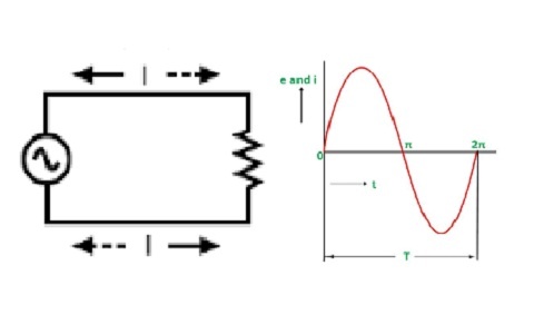
Resistors in AC Circuits - Derivation, Power Dissipation and ...
durango blower resistor wiring diagram picture 2001 Dodge Durango Blower Motor Resistor Wiring Diagram - Database. 2002 jeep grand cherokee cooling fan wiring diagram. Part 1 -how to test the blower motor resistor (2001-2004 dakota, durango). Dakota dodge blower resistor motor wiring 2001 2002 harness replacing burned diy 1999 diagram source.
Circuit Diagram And Its Components - Explanation With Circuit ...
› textbook › direct-currentSimple Series Circuits | Series And Parallel Circuits ... This printout is telling us the battery voltage is 9 volts, and the voltage drops across R 1, R 2, and R 3 are 1.5 volts, 5 volts, and 2.5 volts, respectively. Voltage drops across any component in SPICE are referenced by the node numbers the component lies between, so v(1,2) is referencing the voltage between nodes 1 and 2 in the circuit, which are the points between which R 1 is located.
Physics Tutorial: Parallel Circuits
What is the MOSFET: Basics, Working Principle and Applications MOSFET Block Diagram P-Channel MOSFET. The P- channel MOSFET has a P- Channel region located in between the source and drain terminals. It is a four-terminal device having the terminals as gate, drain, source, and body. The drain and source are heavily doped p+ region and the body or substrate is of n-type.

Block diagram of MPPT stand-alone PV systems with load ...
1988 OMC Ballist resistor location?? - iboats.com The following was excerpted from my OMC Service Manual #507605. Resistor Wire. For Models: All. Special Tools Required: Ohmmeter. Test Procedure - Resistor Wire. Disconnect 20 gauge purple/red resistor wire from ignition coil positive (+) terminal. Disconnect purple lead at back of alternator. Connect ohmmeter between purple/red wire at coil ...
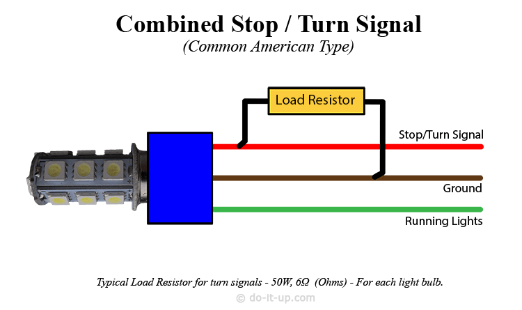
do-it-up.com | How to Install Load Resistors for LED Turn ...
› 12F675A PIC 12F675 Tutorial Including 7 Projects you can Easily ... Circuit diagram. The following diagram shows the above Plugblock circuit in schematic form. It is exactly the same circuit but lets you view the circuit in an easier way and shows the layout of the circuit from the point of view of the circuit block functions rather than how you have to place the components (using the Plugblock).

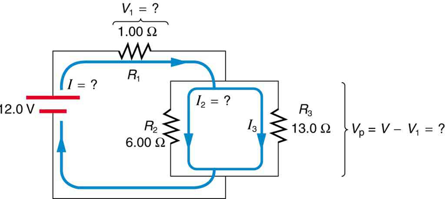
The resistance of each resistor in the circuit diagram shown ...
SparkFun Inventor's Kit Experiment Guide - v4.0 Jan 07, 2014 · Replace 10Kohm Resistor with LED: Alter the circuit be replacing the 10Kohm resistor with an LED (the negative leg should connect to GND). Now what happens when you place your finger over the photoresistor? This is a great way to see Ohm's law in action by visualizing the change in resistance's affect on the current flowing through the LED.

Colorado Blower Motor Resistor and Connector Replacement (Tips and Tricks)
Car Heater and A/C Problem, Hyundai Tiburon Blower Motor Relay Location ... Car heter and A/C Problem, not working, Hyundai Tiburon blower motor relay Location, where is the climate control Resistor, My car not blowing any hot or col...
A Complete Guide to Resistors | RS Components
Where is the fan resistor located on 04 grand caravan where is the fan resistor located on 04 grand caravan please send diagram if have one - Dodge 2000 Caravan question. Search Fixya. Browse Categories Answer Questions . ... Where is the fan resistor located on 04 grand caravan. Please send diagram if have one Posted by dl_graham69 on Sep 07, 2009.

A circuit is built based on the circuit diagram shown. What ...
Electrical Symbols — Resistors | Electrical Diagram Software ... The vector stencils library "Resistors" contains 14 element symbols of resistors for drawing electronic schematics, circuit diagrams and electrical drawings. "A resistor is a passive two-terminal electrical component that implements electrical resistance as a circuit element.
21.1 Resistors in Series and Parallel – College Physics: OpenStax
What is a Resistor? Construction, Circuit Diagram, and ... - ElProCus The circuit diagram of the resistors in parallel connection is shown below. Here the resistors used in the circuit are denoted with R1, R2, and R3. The total resistance of the three resistors can be written as, R Total = R1 + R2 = R3 1/ R Total = 1/ R1 + 1/ R2 + 1/ R3. As a result, Rtotal = R1 * R2 * R3 / R1 + R2 + R3

Electronics | Free Full-Text | New Resistor-Less ...
Electronic Components and Parts Search | DigiKey Electronics Digi-Key is your authorized distributor with over a million in stock products from the world’s top suppliers. Rated #1 in content and design support!
Resistor & Types of Resistors - Fixed, Variable, Linear & Non ...
learn.sparkfun.com › tutorials › sparkfun-inventorsSparkFun Inventor's Kit Experiment Guide - v4.0 Jan 07, 2014 · Replace 10Kohm Resistor with LED: Alter the circuit be replacing the 10Kohm resistor with an LED (the negative leg should connect to GND). Now what happens when you place your finger over the photoresistor? This is a great way to see Ohm's law in action by visualizing the change in resistance's affect on the current flowing through the LED.
operational amplifier - About Negative Gain in Bode Plot ...
PIC 12F675 Microcontroller Tutorial. - Best Microcontroller … Circuit diagram. The following diagram shows the above Plugblock circuit in schematic form. It is exactly the same circuit but lets you view the circuit in an easier way and shows the layout of the circuit from the point of view of the circuit block functions rather than how you have to place the components (using the Plugblock).
Digital Input Pull-Up Resistor | Arduino Documentation ...
Electrical network - Wikipedia An electrical network is an interconnection of electrical components (e.g., batteries, resistors, inductors, capacitors, switches, transistors) or a model of such an interconnection, consisting of electrical elements (e.g., voltage sources, current sources, resistances, inductances, capacitances).An electrical circuit is a network consisting of a closed loop, giving a return path …

Introduction to Electronics: Basic Terminology - Fusion 360 Blog
Why does the location of the resistor matter in this circuit wolowizard: In my understanding, the actual location of a resistor in a serial circuit does not matter. Correct. wolowizard: So why do I get an alert in the second circuit, as shown in Img 2, but not in the first one (Img 1) ? The resistor in the second circuit is not connected to the circuit. It's two pins are also shorted together in row 19.
Basic Resistor Circuit Patterns | SpringerLink
9.06 Unit Test: Electricity Flashcards | Quizlet Mechanical energy is converted to electrical energy. Which statement best describes magnetic fields? Magnetic fields are always found in insulators. Magnetic fields have north and south magnetic poles. Magnetic fields need a conductor. Magnetic fields must have only positive charges. Magnetic fields have north and south magnetic poles.
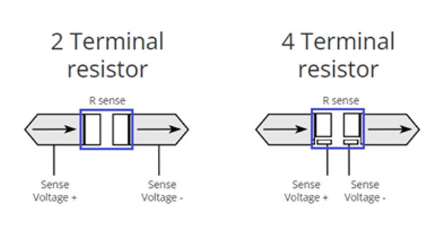
4 terminal current sense resistors in parallel configuration ...
How the Ballast Resistor Works - YouTube This Video explains how the Ballast Resistor Works.For additional How-to Tutorials Visit our Website:

19.2 Series Circuits | Texas Gateway

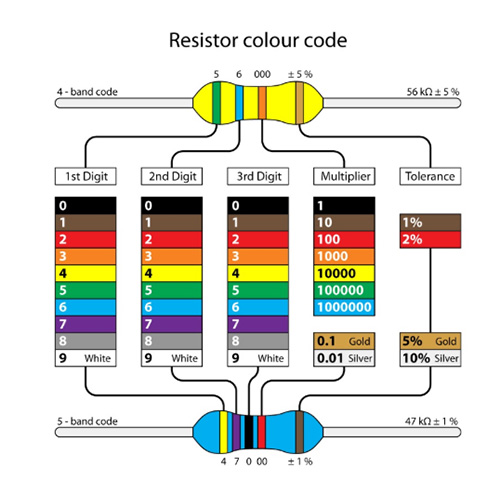
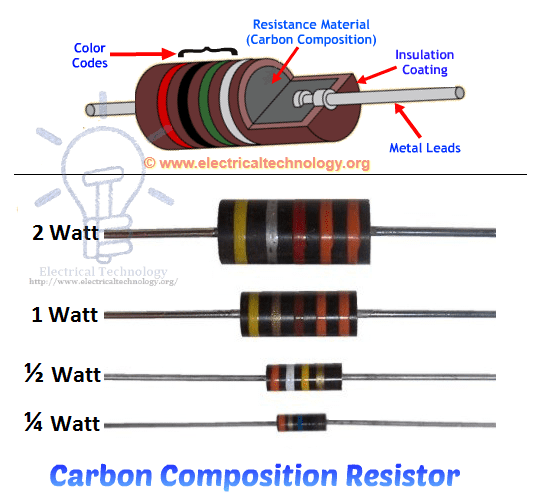
Circuit Notes: How to Read a Resistor | Jameco Electronics
What is a Resistor? Construction, Circuit Diagram and ...
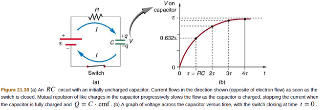
Chapter 21, Problem 36CQ | bartleby

Lesson Worksheet:Design of the Ohmmeter | Nagwa
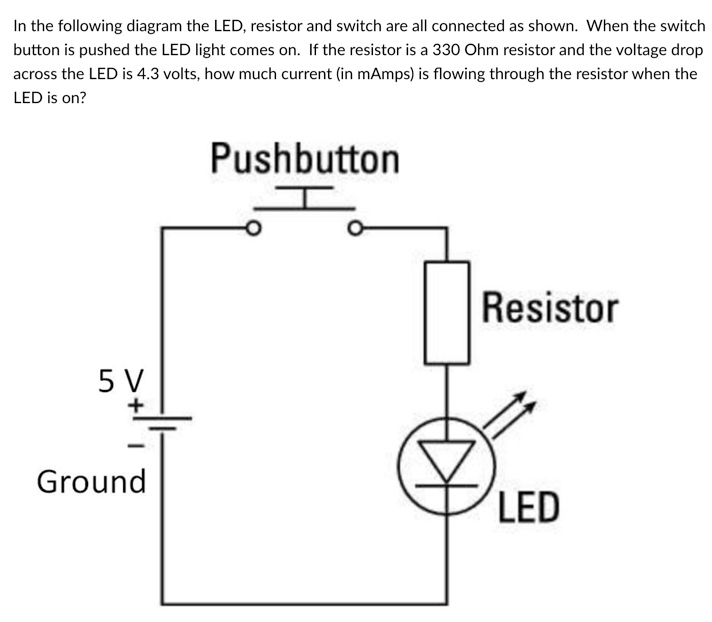
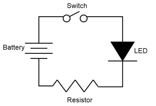
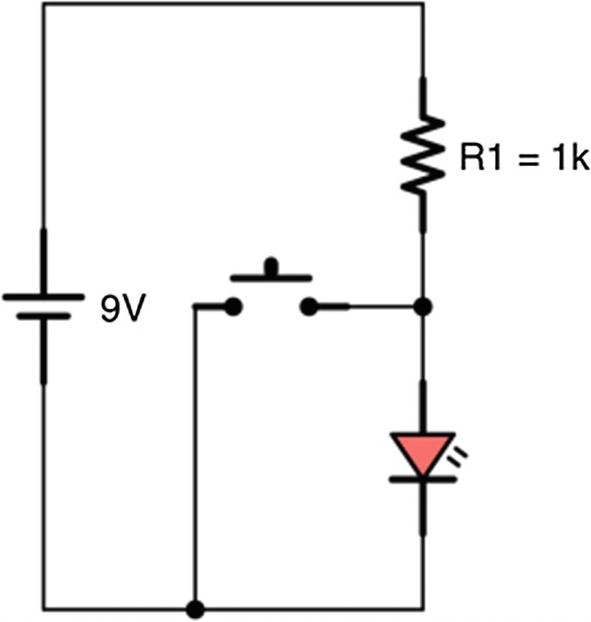
Solved In the following diagram the LED, resistor and switch ...
21.1 Resistors in Series and Parallel – College Physics: OpenStax

Electronic symbol - Wikipedia
Heater Blower Motor Resistor | Cars.com
Resistor Circuit Diagrams: Understanding Connections and ...
Questions
Circuit diagram of a voltage divider based on a adjustable ...

11.2 Ohm's Law | Electric circuits | Siyavula
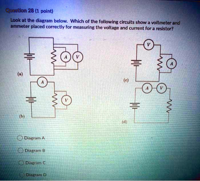
SOLVED: Qucstlon 28 (1 point) Look at the diagram below ...

Circuit diagram, including the power supply, dump resistors ...
Physics Tutorial: Series Circuits

Electricity class 10: CBSE previous question paper problems ...
Solved A) First, let us consider a resistor with resistance ...
Resistor : Construction, Circuit, Working, Properties & Its ...
Circuit network theory of n-horizontal bridge structure ...
Digital Potentiometer | Resistor Types | Resistor Guide

Tunable Floating Resistor Based on Current Inverting ...
0 Response to "42 where is the resistor located on this diagram"
Post a Comment