44 plc ladder diagram for traffic light
Control Of Traffic Light Ladder Logic Diagram - Pinterest Dec 1, 2019 - Control Of Traffic Light Ladder Logic Diagram. Dec 1, 2019 - Control Of Traffic Light Ladder Logic Diagram. Pinterest. Today. Explore. When autocomplete results are available use up and down arrows to review and enter to select. Touch device users, explore by touch or with swipe gestures. ... PLC Training - RSlogix Simulator (Size ... Traffic light using plc - SlideShare Mitsubishi FX PLC Crosswalk Programming Ladder Diagram arco zhang. Programmable Logic Controllers Anchit Walia. Four elevator controller Bhagwat Singh Rathore ... Traffic light using plc 1. On Submitted by Banzadio salazaku Roll 2013010100016 B tech E and I 6th sem Submitted to Mrs. Arti Nagpal 2. Preface An industrial PLCs system is used for ...
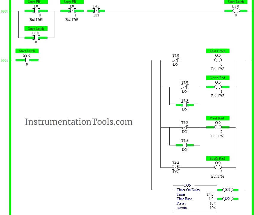
PLC Ladder logic example for beginners: Four-Way traffic light control ... Ladder explanation: When the memory bit is on and since the timer DB7 done bit is (NC) contact state. The timer DB0 starts to run according to the preset time. Since the timer DB0 done bit is (NC) contact state as a result the output East Green (%Q0.0) will be on until it reaches the preset value of the timer DB0.
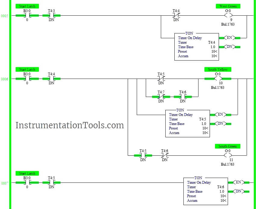
Plc ladder diagram for traffic light
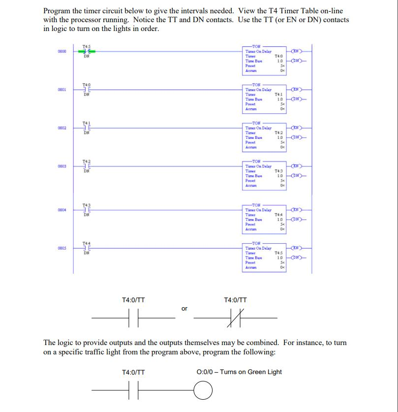
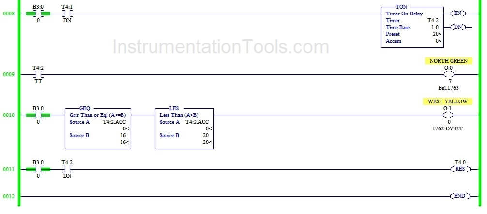
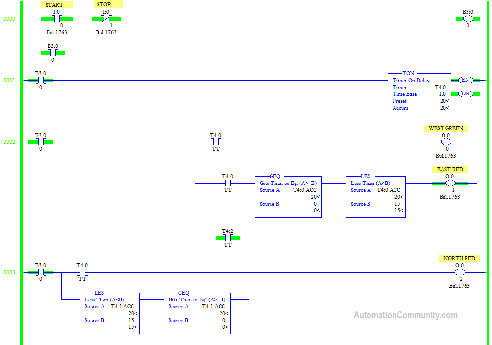
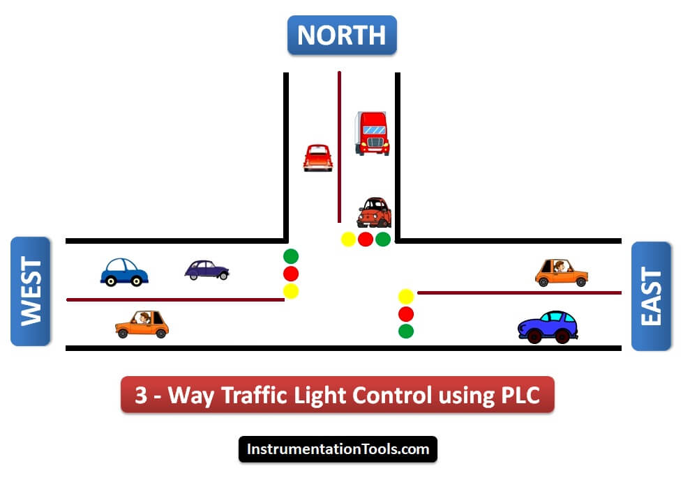
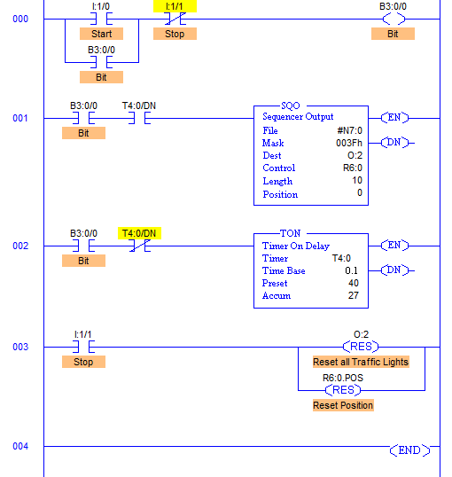
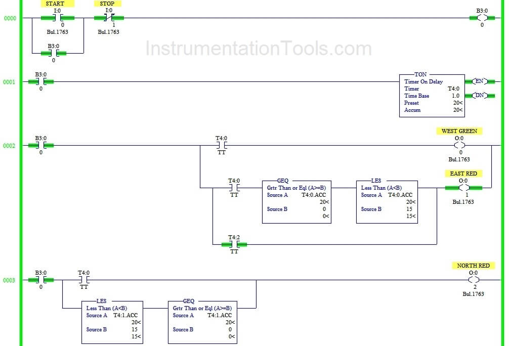
PLC based 4 Way Traffic Light Control System - Inst Tools This PLC ladder logic gives the solution to control city traffic using programmable logic control. 4 Way Traffic Light Control, Problem Solution, They are so many ways to write a program for traffic light control ex: sequencer output method but in this normal input, outputs and timers are used. Three way Traffic Light Control using PLC - Automation Community Write the ladder logic for this 3-way traffic light control using the above sequence. Inputs and Outputs Three way Traffic Light Control PLC Program Description: RUNG 000. Latching rung to operate the system through Master Start and Stop PB. 2. RUNG 001 and RUNG 0002. Starting the timer to turn on first output West Green so east and west should ... Inilah Ladder Diagram Untuk Traffic Light Control (Lampu ... - NIGURU Then pada bahasa pemrograman tingkat tinggi seperti VB, Delphi, dan lain sebagainya. Untuk menjelaskan beberapa instruksi tersebut, Niguru.com menggunakan rangkaian traffic light control (lampu pengatur lalu lintas). Demikianlah penjelasan mengenai ladder diagram untuk rangkaian lampu pengatur lalu lintas. Selamat mencoba ..
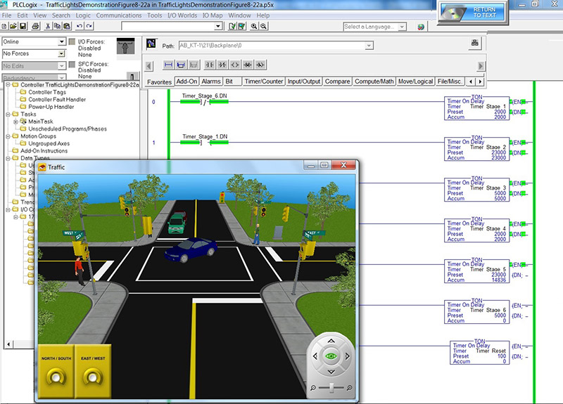
Plc ladder diagram for traffic light. IOP Conference Series: Earth and Environmental Science PAPER OPEN ... research and develop an intelligent traffic light called PLC control system.It uses PLC as control core,using a sensor module for receiving real-time information of vehicles, traffic ... Figure3. ladder diagram 5.1 main program design System based on PLC internal clock, judge the current time is in a period during the day or at night, if ... Intelligent Traffic Light Based on PLC Control - ResearchGate Figure 4. traffic comparison ladder diagram . 5.2 Normal working mode . ... This document research and development of intelligent traffic lights called PLC control system. PLC Ladder Programming tutorial for beginners in Traffic Signal | plc ... #TrafficSignal #TrafficLight #PlcProgramming #plc #plctutorial #plcbasics #ladderlogic #ladderdiagram #programmablelogiccontrollerTutorial for Traffic Signal... Traffic Light Control using PLC Ladder Logic - Inst Tools This PLC program gives the solution to control heavy traffic jams using programmable logic control. Traffic Light Control using PLC, Problem Solution, They are so many ways to write a program for traffic light control ex: sequencer output method but in this normal input, outputs and timers are used.
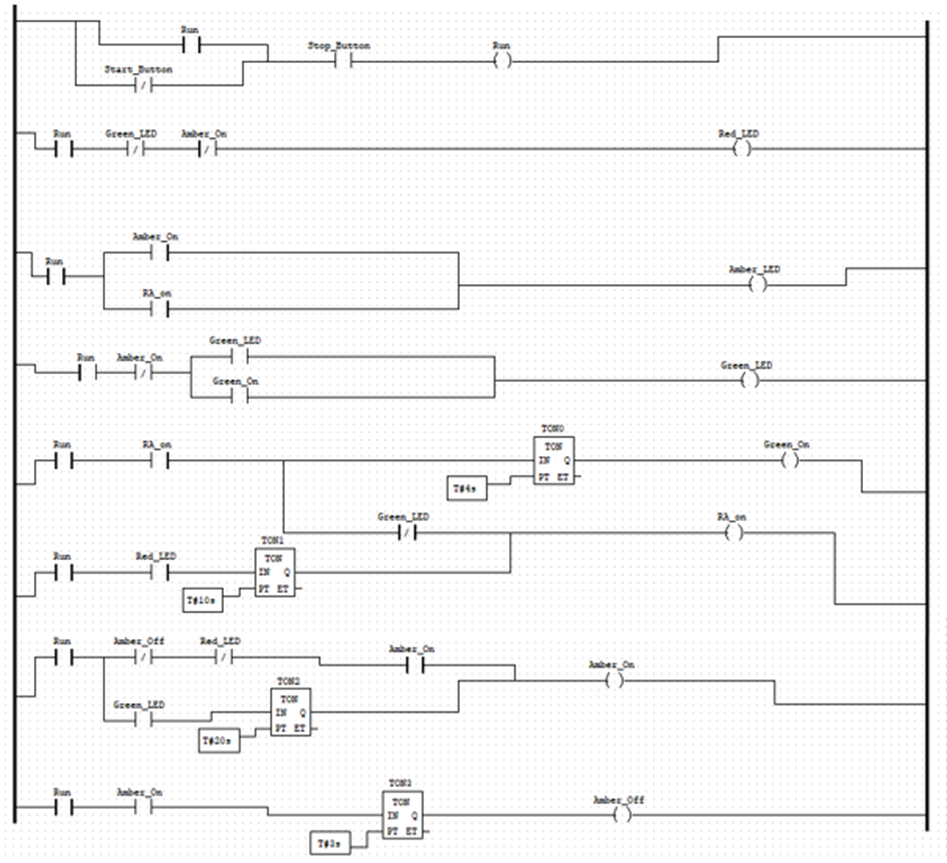
kursus plc, pelatihan plc,HMI,SCADA jakarta,depok,bekasi,tangerang KURSUS PLC; JASA PROGRAM PLC; Ladder diagram traffic light this ladder diagram for two way traffic light , please see the lay out below: I use omron PLC and I have determine the I/O below: No: Devices. Address. 1: green lamp line #1: 01.00: 2: Yellow lamp line#1: 01.01: 3: Red lamp line#1: 01.02: 1: PDF Plc ladder diagram for traffic light control using timers pdf - ASBU Plc ladder diagram for 2 way traffic light control using timers. Plc ladder diagram for traffic light control using timers pdf. Do-More, Do-More Designer, PLC, PLC Basics, PLC Learn May 10, 2015 garrys Leave a comment In part 1 we examined the writing of PLC programs to control a traffic light using discrete bits and then using the punctual ... "[Help] PLC ladder diagram for traffic light (4way)" Steve Bailey - (85 posts): Feb-06-02, 09:29 AM (EST) 3. "RE: [Help] PLC ladder diagram for traffic light (4way)" You won't make any friends among the drivers on Avenue A and Boulevard B if you make them wait for a full minute for a single vehicle to enter from Causeway C or D Drive. traffic light control using plc ladder logic | ACC Automation May 10, 2015. No Comments. In part 1 we looked at writing PLC programs to control a traffic light using discrete bits and then using timed sequencing using indirect addressing. Part 2 used indirect addressing for inputs as well as output to control the sequence of pneumatic (air) cylinders in the program. Part 3 returned to the traffic light ...
Instruction list to ladder diagram for traffic light | GGL ホーム › フォーラム › 【トリマ】お友達紹介コード掲示板 › Instruction list to ladder diagram for traffic light このトピックは空です。 1件の投稿を表示中 - 1 - 1件目 (全1件中) PLC Program for Traffic Light Control - PLC Tutorial Point PLC Program for Traffic Light Control, by Vinod Kumbhar, PLC Program, for Traffic Light Control, Control Purpose: Enabling the traffic lights to work by Start button X0 and to stop by Stop button X1. Setting the time of red light in East-West direction as 60 sec and North-South direction with a heavier traffic as 30 sec. The time of red light in, PLC Training 52 - Traffic Light Control using PLC Ladder Logic Write a PLC program for two-way traffic light control using ladder logic programming.4 Way Traffic Light Control Logichttps://instrumentationtools.com/plc-ba... Automation Community - PLC and SCADA Industrial Automation Courses Online PLC Course - Programmable Logic Controllers . Editorial Staff . June 28, 2022 . Automation Community provides you access to a free online PLC course to learn the basics of programmable logic controllers. Solenoid Valve Testing Procedure . Editorial Staff . June 5, 2021 .
LADDER Practical Exercises - Lesson2 - plc4me.com Practical Exercises 7 : Control the sequence of lights to operate sequentially. 1 The sequence of 5 lights operates on the following principles : + Turn off the system with the S1 button, turn off the system with the S2 button, switch Automatic / Manual mode (A/M) with the S3 button. + Auto Mode : When the Up button is pressed, the lights turn ...
ladder diagram one way traffic light - MathewSpain's blog Ladder diagram consists of one vertical line found on the left hand. conditions determines when and in what way. Traffic Light with PLC; Weighing Machine Using PLC, Here's one way of making sure the traffic light is always "green": a team of researchers at the University of Nebraska-Lincoln is working on a three-year green. TheLearningPit,
Plc Ladder Diagram For Traffic Light Control Using Timers Pdf Traffic Light Automation Control Program Designed By A Student Scientific Diagram, Traffic Light Control Using Plc Ladder Logic Programming, Four Way Traffic Control By Using Plc Technical Hub, Smart Traffic Control System Using Plc Programming And Ld Diagram, Four Way Traffic Control By Using Plc Technical Hub,
plc programming examples traffic light | ACC Automation In part 1 we looked at writing PLC programs to control a traffic light using discrete bits and then using timed sequencing using indirect addressing. Part 2 used indirect addressing for inputs as well as output to control the sequence of pneumatic (air) cylinders in the program. Part 3 returned to the traffic light application and expand our program significantly.
Traffic Light Control using PLC Ladder Logic Programming The traffic light is one of the classic examples in PLC ladder logic. We can take four directions (North, South, west, and east) with three output lamps (Green, Red, and Yellow). You can build your own concept for making logic for this example. Follow below tabular column - Logic for the four way traffic light, List of Inputs and Outputs,
PLC Ladder Logic Diagram for Traffic Signal. - Instructables PLC Ladder Logic Diagram for Traffic Signal. By muneeb4889 in Circuits Software. 4,191. 2. Download. Favorite. By muneeb4889 muneeb aslam.
PLC Ladder Logic Programming Examples with detailed explanation Look at the ladder logic diagram, how simple it is. X0, X1, X2, and X3 are the open type Input contacts while Y0, Y1, Y2, and Y3 are the output contacts. Now, using this program any load can be turned ON and turned OFF. If you write the same program in Arduino, it will be a long program using multiple IF conditions and flags.
mitsubishi plc traffic light ladder diagram - PLC Controller - Google mitsubishi plc traffic light ladder diagram. ncusbpod.dll. no ssf files found. op320-a software download. Power failure delay type time relay physical wiring diagram. qs-fs01. siemens s7 date and time format. siemens s7 date and time format. siemens s7 date and time format.
FOUR WAY TRAFFIC CONTROL BY USING PLC - Technical Hub 4. Write your code in the program window by using timers, counters, memory, arithmetic blocks. 5. For our four way traffic light control project we used 12outputs and 2 inputs. 6. Take 2 inputs and 12 outputs according to our requirement. 7. The next 7 Rungs we have timers used to turn on and turn off the 12 outputs. 8.
Smart Traffic Control System using PLC Programming and LD Diagram Prerequisite: Basic Parts of Ladder Diagram in PLC Programming, PLC Tools Used in the Project, Tools recruitment are as follow. Two Push-Button [PB1 & PB2] Three Lamp Signal [Q1, Q2 & Q3] One Memory [M] Three Timers [T1, T2 & T3] This is how the LD diagram looks like with these components on ABB PLC. Program on ABB PLC Software,
Plc Ladder Logic Diagram For Traffic Light - Americanwarmoms.org Traffic Light Control Using Plc Ladder Logic Program, Traffic Light Automation Control Program Designed By A Student Scientific Diagram, Three Way Traffic Light Control Using Plc Automation Community, Traffic Light Signal Project 2021 Best Plc Simulation Programming Tutorial You,
Inilah Ladder Diagram Untuk Traffic Light Control (Lampu ... - NIGURU Then pada bahasa pemrograman tingkat tinggi seperti VB, Delphi, dan lain sebagainya. Untuk menjelaskan beberapa instruksi tersebut, Niguru.com menggunakan rangkaian traffic light control (lampu pengatur lalu lintas). Demikianlah penjelasan mengenai ladder diagram untuk rangkaian lampu pengatur lalu lintas. Selamat mencoba ..
Three way Traffic Light Control using PLC - Automation Community Write the ladder logic for this 3-way traffic light control using the above sequence. Inputs and Outputs Three way Traffic Light Control PLC Program Description: RUNG 000. Latching rung to operate the system through Master Start and Stop PB. 2. RUNG 001 and RUNG 0002. Starting the timer to turn on first output West Green so east and west should ...
PLC based 4 Way Traffic Light Control System - Inst Tools This PLC ladder logic gives the solution to control city traffic using programmable logic control. 4 Way Traffic Light Control, Problem Solution, They are so many ways to write a program for traffic light control ex: sequencer output method but in this normal input, outputs and timers are used.
















0 Response to "44 plc ladder diagram for traffic light"
Post a Comment