38 statics free body diagram examples
PDF EQUILIBRIUM OF A RIGID BODY & FREE-BODY DIAGRAMS Today's Objectives 1. Draw an outlined shape. Imagine the body to be isolated or cut "free" from its constraints and draw its outlined shape. 2. Show all the external forces and couple moments. These typically include: a) applied loads, b) the weight of the body, and c) support reactions (can be difficult). Idealized model Free-body diagram PDF Statics of Bending: Shear and Bending Moment Diagrams Figure2:Acantileveredbeam. Free-body diagrams Asasimplestartingexample,considerabeamclamped(\cantilevered")atoneendandsub-jectedtoaloadPatthefreeendasshowninFig.2 ...
Fundamentals of Engineering Exam Review | Coursera We show how to draw a meaningful free body diagram with different types of supports. Then how to analyze pulleys and compute static friction forces and solve problems involving friction. The concept and major characteristics of trusses are discussed, especially simple trusses, and we show how to analyze them by the method of joints and the method of sections.

Statics free body diagram examples
Statics eBook: Shear and Moment Diagrams I - University of Oklahoma This process can be repeated for for the section to the right of the load. The free-body diagrams for the two pieces are shown at the left. For this section, it is easier to solve for the piece to the right of the cut. ΣF y = 0 2F/3 + V 2 = 0 V 2 = -2F/3 . The moments about the left edge can be used to determine the bending moment. ΣM cut = 0 Statics Free Body Diagram Examples - Google Groups All groups and messages ... ... 4.2 Rigid Body Free Body Diagrams - Engineering Mechanics: Statics Following what we learned in Section 2.2 on particle Free-Body Diagrams (FBDs), this section will expand on that for rigid bodies. The biggest difference between a particle and rigid body FBD is where the force is applied. In a rigid body FBD, you have to be precise about pointing the head of the force arrow to the location where it applied.
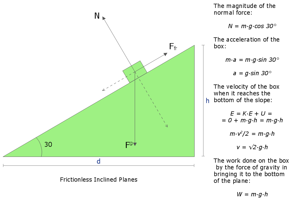
Statics free body diagram examples. Free Body Diagram Example | Statics - YouTube First of all, the video introduces with the given exemplary diagram that shows a block is at rest condition over a slope having 30 degree angle with the ground. The mass of the block has given as 1... 4.3 Rigid Body Equilibrium Equations – Engineering Mechanics: Statics As with particles, the first step in finding the equilibrium equations is to draw a free body diagram of the body being analyzed. This diagram should show all the force vectors acting on the body. In the free body diagram, provide values for any of the known magnitudes, directions, and points of application for the force vectors and provide variable names for any unknowns (either … Statics: Free Body Diagrams Possible free-body diagrams for two common situations are shown in the next two examples. 🔗 Example 5.2.5. Fixed support. The cantilevered beam is embedded into a fixed vertical wall at . A. Draw a neat, labeled, correct free-body diagram of the beam and identify the knowns and the unknowns. Solution. 🔗 Example 5.2.6. Frictionless pin and roller. Engineering Statics: Free Body Diagram, Frames, Examples An educational video from Actus Potentia. Free Body Diagram, frames, basic principles, thumb rules, examples.
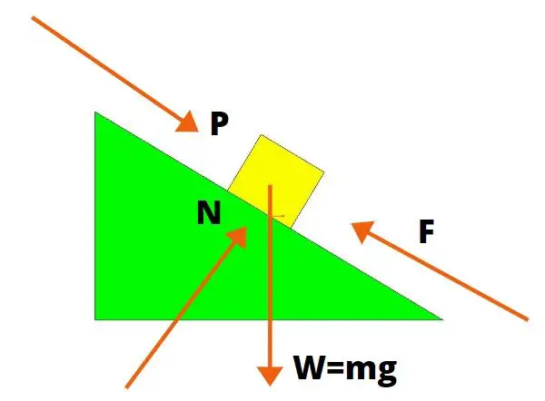
12.2 Examples of Static Equilibrium - OpenStax Equation 12.21 and Equation 12.22 are two equations of the first equilibrium condition (for forces). Next, we read from the free-body diagram that the net torque along the axis of rotation is. + r T T y − r w w y = 0. 12.23. Equation 12.23 is the second equilibrium condition (for torques) for the forearm. Statics eBook: Equilibrium & Free Body Diagrams - University of Oklahoma Free Body Diagram Example : A Free-body diagram (FBD) is an essential tool when the forces on an object need to be determined using equilibrium equations. They help focus attention on the object of interest in order to determine the forces acting on it. Creating FBD's is a straightforward process: Identify the object that will be isolated. Free Body Diagrams, Tutorials with Examples and Explanations Example 8 : A system with two blocks, an inclined plane and a pulley. A) free body diagram for block m 1 (left of figure below) 1) The weight W1 exerted by the earth on the box. 2) The normal force N. 3) The force of friction Fk. 4) The tension force T exerted by the string on the block m1. B) free body diagram of block m 2 (right of figure below) Force - Wikipedia In physics, a force is an influence that can change the motion of an object.A force can cause an object with mass to change its velocity (e.g. moving from a state of rest), i.e., to accelerate.Force can also be described intuitively as a push or a pull. A force has both magnitude and direction, making it a vector quantity. It is measured in the SI unit of newton (N).
Statics: Free Body Diagrams The “free-body” in free-body diagram means that the body to be analyzed must be free from the supports that are physically holding it in place. Simply sketch a quick outline of the object as if it is floating in space disconnected from everything. Do not draw free-body diagram forces on top of your problem drawing — the body needs to be ... 6.2 Shear/Moment Diagrams – Engineering Mechanics: Statics Shear Diagram. To create the shear force diagram, we will use the following process. Solve for all external forces acting on the body. Draw out a free body diagram of the body horizontally. Leave all distributed forces as distributed forces and do not replace them with the equivalent point load. Lined up below the free body diagram, draw a set ... Free Body Diagrams - Design Technology For example, for a block resting on the ground - the support from the ground must be transformed into a vertical resisting force. For a steel eye-loop anchored to the ground, pulled on by a diagonal rope - the rope must become a force vector in the identical direction, and the anchor must be transformed into perpendicular force vectors. Engineering Fluid Mechanics - Staffordshire University Download free ebooks at bookboon.com Please click the advert Engineering Fluid Mechanics 5 Contents 2.6 Darcy Formula 59 2.7 The Friction factor and Moody diagram 60 2.8 Flow Obstruction Losses 64 2.9 Fluid Power 65 2.10 Fluid Momentum 67 2.11 Tutorial Problems 75 3 External Fluid Flow 77 3.1 Regimes of External Flow 77 3.2 Drag Coefficient 78
Free-body diagram of static conditions | Download Scientific Diagram
Equilibrium and Statics - Physics Classroom To illustrate this, consider a 10-Newton picture held by three different wire orientations as shown in the diagrams below. In each case, two wires are used to support the picture; each wire must support one-half of the sign's weight (5 N). The angle that the wires make with the horizontal is varied from 60 degrees to 15 degrees.
engineering statics :equilibrium
Statics - Free Body Diagram - YouTube The free body diagram is one of the most important ideas in statics. Here's a description along with an easy example.

How to Make a Free Body Diagram - Saint Mary's Physics Demos
Statics free body diagram - SlideShare Statics (MET 2214) Example 1 The sphere has a mass of 6 kg and is supported as shown. Draw a free-body diagram of the sphere, cord CEsphere, cord CE, and the knot at C.the knot at C. 17. Statics (MET 2214) Sphere There are two forces acting on the sphere. These are its weight and the force of cord CE. The weight is: W = 6 kg (9.81 m/s2 ) = 58.9 N.
statics - Free Body Diagram Problem - Engineering Stack Exchange
Simply Supported Beams Free Body Diagram Example | Statics for more FREE video tutorials covering Engineering Mechanics (Statics & Dynamics)The objectives of this video are to give an introducto...
Statics
6.2 Shear/Moment Diagrams - Engineering Mechanics: Statics Draw the shear force and bending moment diagrams for the cantilever beam supporting a concentrated load of 5 lb at the free end 3 ft from the wall. 1. Draw a FBD of the structure 2. Calculate the reactions using the equilibrium equations (may not need to do this if choosing a cantilever beam and using the free side for the FBD).

Free Body Diagram Example | Statics - YouTube
Shear and moment diagram - Wikipedia Shear and bending moment diagrams are analytical tools used in conjunction with structural analysis to help perform structural design by determining the value of shear force and bending moment at a given point of a structural element such as a beam.These diagrams can be used to easily determine the type, size, and material of a member in a structure so that a given set of …

An Easy Guide to Understand Free Body Diagrams in Physics
Statics: 2D Rigid Body Equilibrium Section 5.4 2D Rigid Body Equilibrium. Two-dimensional rigid bodies have three degrees of freedom, so they only require three independent equilibrium equations to solve. The six scalar equations of can easily be reduced to three by eliminating the equations which refer to the unused \(z\) dimension. For objects in the \(xy\) plane there are no forces acting in the \(z\) direction to …
ME Dynamics - Multiple ideal pulleys + an inclined plane | Physics Forums
Statics - Engineer4Free: The #1 Source for Free Engineering Tutorials Vector concepts apply to vectors in any dimension. 1. Draw a vector in standard position, or anywhere 2. Find the scalar multiple of a vector 3. Adding vectors 4. Subtracting vectors 5. Find the dot product of vectors 6. Find the length of a vector and give a unit vector in it's direction 7. Determine orthogonality and angles between vectors 8.

Free body diagram Concept in Mechanics
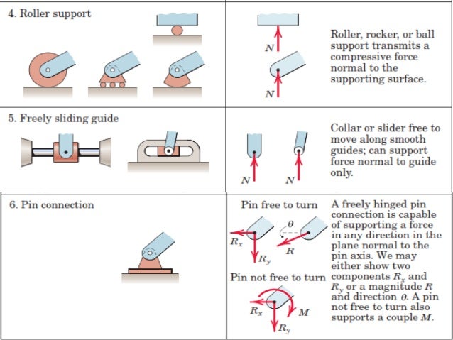
Statics of Non-Concurrent Force Systems: Free-Body Diagram of a Rigid Body this task, and will look at some examples of free-body diagrams. Hints in Drawing Free-Body Diagrams 1. Identify the member of interest, and separate (free, cut) it from the rest of the system at the supports and points of contact (joints) with other members. 2. - All the applied forces (including weight if specified) and couple moments.
What is Free Body Diagram : Definition with examples | RiansClub
Engineering Mechanics Statics (13th Edition) - BAIXARDOC Emphasis on Free-Body Diagrams. Drawing a free-body diagram is particularly important when solving problems, and for this reason this step is strongly emphasized throughout the book. In particular, special sections and examples are devoted to show how to draw free-body diagrams. Specific homework problems have also been added to develop this ...

Free Body Diagram (FBD) and Equilibrium Concepts in Mechanics - YouTube
Module 15: Shear Force Diagrams - Space Trusses; Shear Force … 21-08-2015 · Module 17: Shear Force and Bending Moment Diagrams – Examples 5:33. Taught By. Dr. Wayne Whiteman, PE. Senior Academic Professional. Try the Course for Free. Transcript. Explore our Catalog Join for free and get personalized recommendations, updates and offers. Get Started. Coursera Footer. Start or advance your career. Google Data ...
What is meant by the concept of a free-body diagram in physics? - Quora
Statics eBook: Equilibrium & Free Body Diagrams - University of Oklahoma a. As with all statics problem, a free-body diagram will assist in solving the problem. In this example, all forces acting on the elevator cabin is first analyzed. The 5000 lb weight is divided evenly between the cables due to symmetry. Consequently the force of each cable will be P = 5000 / 2 = 2,500 lb

An Easy Guide to Understand Free Body Diagrams in Physics | Physics ...
4.2 Rigid Body Free Body Diagrams - Engineering Mechanics: Statics Following what we learned in Section 2.2 on particle Free-Body Diagrams (FBDs), this section will expand on that for rigid bodies. The biggest difference between a particle and rigid body FBD is where the force is applied. In a rigid body FBD, you have to be precise about pointing the head of the force arrow to the location where it applied.
32 Free Body Diagram Problems And Solutions Pdf - Wiring Diagram List
Statics Free Body Diagram Examples - Google Groups All groups and messages ... ...

Statics 3-1b Creating a Free Body Diagram - YouTube
Statics eBook: Shear and Moment Diagrams I - University of Oklahoma This process can be repeated for for the section to the right of the load. The free-body diagrams for the two pieces are shown at the left. For this section, it is easier to solve for the piece to the right of the cut. ΣF y = 0 2F/3 + V 2 = 0 V 2 = -2F/3 . The moments about the left edge can be used to determine the bending moment. ΣM cut = 0

Force | Free Body Diagrams | Physics | Don't Memorise - YouTube
0 Response to "38 statics free body diagram examples"
Post a Comment