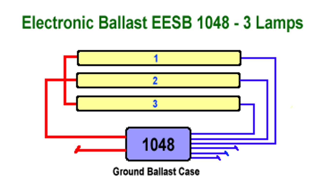
38 t5 ballast wiring diagram
4 Lamp T5 Wiring Diagram | Manual E-Books - 4 Lamp 2 Ballast Wiring Diagram. Additionally, Wiring Diagram gives you enough time frame during which the projects are for being accomplished. You'll be in a position to learn exactly when the tasks needs to be accomplished, that makes it much easier for you to properly handle your time and effort. Connect the white wire “neutral” to each lamp holder on the “power” side of the fixture per the wiring diagram. Use UL approved and appropriately rated wire ...1 page
Ballast” diagram may not necessarily take you to another “Two Lamp Ballast” diagram. To aid in locating specific diagrams, each has been bookmarked and categorized in the navigation window. 2) USING THE FIND COMMAND Some diagrams feature a Model List for reference. If you know the actual model number of the AC ballast that the emergency ...

T5 ballast wiring diagram
Wiring diagrams and installation examples, page 7 EM T5 BASIC, 220 - 240 V 50/60 Hz T5 BASIC version ... Wiring Lamp/ballast/supply 8 - 9 mm wire preparation: 0.5 - 0.75 mm² ... This means, for example, in a linear T8 or T5 luminaire the mains wiring should be routed along one side of the luminaire body, while the wires T8/T5 Ballast Wiring Diagram available for reference online at EML Direct. All diagrams are available in PDF format for viewing on almost any device. Here you will find a selection of wiring diagrams for converting existing T5 and T8 fluorescent fittings to emergency operation using the ECK range of conversion kits. Select the proper voltage lead and cap the unused lead. When the XEB-T5-5-B is used with a switched fixture, the A.C. input to the emergency ballast must be connected ahead of the fixture switch. Refer to the figure below for switched and unswitched fixture wiring diagrams. INSTALLATION INSTRUCTIONS Figure 1 Figure 3 Ballast Wiring Block Diagram
T5 ballast wiring diagram. Ballast Wiring Guide standard layouts for default ballasts September 2014 labor saving master satellite (ls) — A master satellite configuration with separately controlled luminaires 1 - 4-LamP BaLLaStS (t8) 1 & 2-LamP BaLLaStS (t5/t5HO) 1 lamp 2 lamps 3 lamps 4 lamps 2 lamps 1 lamp Digital DALI electronic ballasts for T5-eco fluorescent lamps Lamp type Wattage No. of lamps Ballast EEI Dimensions Connection Weight Circuit power 2) Mains current 2) Lamp power (p.14) (g) (W) (A) (W) T5 eco 14 eco 1 EL1x14-35iDim 4) A1 BAT 1 1 250 17 0.08-0.07 13.7 14 eco 2 EL2x14-35iDim 4) A1 BAT 2 2 330 32.5 0.15-0.14 13.7 Mount the I-320 in the ballast channel at least 1/ 2″ away from the A.C. ballast(s). When battery packs are remote mounted, consult Customer Service for the maximum allowable distance between the battery pack and the lamp. 3.WIRING Refer to the wiring diagrams on the back page for the appropriate wiring of lamp(s) and ballast. Install in ... 177 Broad Street, 12th Floor, Stamford, CT 06901 T - 805 578 2536 E - Support@rvlti.com rvlti.com PC003_v05 (2016-08-02) Ballast Compatibility List and Guide - Uni-Fit T5 Tube Lamps. This list provides the known and tested compatible ballasts for Revolution Lighting Uni-Fit LED T5 Tube
Ballast Wiring Block Diagram SWITCHED FIXTURE UNSWITCHED FIXTURE Figure 2 LED COMBO SWITCH LED COMBO SWITCH WHITE LED COMBO SWITCH BALLAST CHANNEL COVER Page 2 BAL T5-500 BAL T5-500 * * * * 5. Labels: Attach the appropriate labels adjacent to the LED COMBO SWITCH. The 'Caution' and the Re-lamping labels must be on the fixture in a readily ... ULTRA ELECTRONIC BALLAST ULTRA MAX ELECTRONIC BALLAST MAX ULTRAMAX ULTRAMAX ELECTRONIC BALLASTS TM ELECTRONIC BALLASTS 1-6 transforming the power of light™ For more information, visit www.gelighting.com 1-7 CHOOSING THE RIGHT BALLAST IS SIMPLE. The easy-to-understand model numbering system helps you choose and install the right model. Wiring diagrams and installation examples, page 6. PC T5 PRO lp, 24 – 80 W. T5 high output, T8 and TC-L fluorescent lamps (CFL). 5 - 150-250w mh 480v 6 - 250-1000w hps 480v electronic ballast wiring diagrams 1 - t5 2 lamp 2 - t5 4 lamp 7- pulse start mh 9 - 5-tap hps 8 - 5-tap mh 4 - t8 3 lamp 240v 277v com com 120v 208v 480v cap lamp ignitor tap x3 x2 x1 277v black 240 tan 208 purple 120v orange white common blk/ wht blk/ wht/red blue cap red ignitor lamp yellow 5 - t8 ...
Description: Wiring Fluorescent Light Ballast Replacement – Wiring Diagram And in 4 Lamp T5 Ballast Wiring Diagram, image size 800 X 522 px, and to view image details please click the image.. Truly, we have been noticed that 4 lamp t5 ballast wiring diagram is being just about the most popular issue at this moment. So that we tried to uncover some terrific 4 lamp t5 ballast wiring diagram ... Ballast Wiring Diagram T5 . October 25, 2019 1 Margaret Byrd . 0 . Tridonc t5 twin ballast wiring change electronic for fluorescent universal accustart5 b228punv c 2 lamp rapid start 4 lamps tridonic diagram reef2reef saler and reef aquarium forum sign ballasts smart wire parallel ... Jan 17, 2013 · RIP 1959-2015. Looking at the ballast wiring diagram, black, white, and grey wires to orange quick disconnect. Line on diagram going to grey has a symbol for a switch and letters "sw" next to symbol. Wire push in on line side of orange quick disconnect (for grey fixture wire) is ringed with broken black line, un-broken black line for black. BALLAST TABLE BALLAST FACTOR Ratio of the lamp’s lumen output on the specified ballast to the lamp’s lumen output when operated by a reference ballast. WIRING DIAGRAM References the wiring diagram to use. INPUT POWER Total power input to the ballast which includes lamp watts and ballast losses. PRODUCT CODE Abbreviated product description
Ballast bypass Led Wiring Diagram - wiring diagram is a simplified usual pictorial representation of an electrical circuit. It shows the components of the circuit as simplified shapes, and the capability and signal connections amongst the devices. A wiring diagram usually gives recommendation about the relative twist and harmony of devices ...
3 1. Find your lamp type. 2. Find the quantity and wattage of lamps. 3. Look across and find the ballast you need. 4. The colored number represents wiring diagram.
2 Philips Advance Ballast Quick Guide 3 Introduction 4 T8 ballasts 6 T5 ballasts 7 CFL ballasts 8 Magnetic T12 conversion to electronic 9 T12 ballasts 10 Dimming ballasts 11 Circline and signage ballasts 12 HID ballast kits specifications, wiring diagrams, and more. Another way to differentiate the tubes is by knowing the diameter for each.
Wiring for instant start ballasts differs from that for rapid start ballasts and programmed start ballasts. In addition, the rapid and programmed start ballasts have two options for wiring when being connected with more than two T5 lamps (see figure 6). Figure 6 illustrates the two wiring methods of T5 ballasts. In series wiring, electrodes of ...
LED T5 Tue Series RAB Ligting is committe to creating ig-uality aorale well-esigne an energ-ecient LED ligting an controls tat mae it eas or electricians to install an en users to save energ. We' love to ear our comments. Please call te Marketing Department at 888-RAB- or email: marketingraligting.com Program Start Ballast Wiring Diagram ...
Wiring Diagram Finder. Find wiring diagrams for your WorkHorse, WHAM, or LongHorse ballasts. Select your lamp type from the list below. Select the lamp quantity and wattage. Select the ballast family. Select your ballast. To download the diagram, right click the image when it appears and choose "Save as…". Twin.
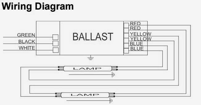
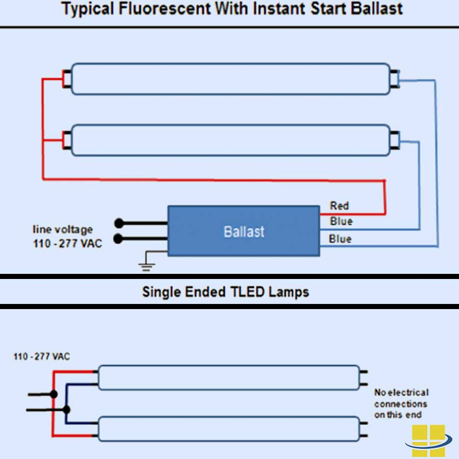
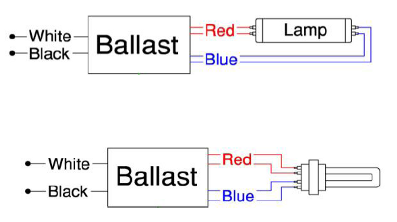
IMPORTANT: The below ballast wiring diagrams represent a typical configuration. Actual ballast wiring varies according to the ballast model. There is no need to change the socket (if it is in good condition) to operate double ended lamps, regardless of the type of sockets.
specifications, wiring diagrams, and more ... Ballast Factor Other T5 & T5/HO Lamps Operated Philips Advance Model Grainger F14T5 F21T5 F28T5 F35T5 F24T5/HO F39T5/HO F54T5/HO SKU 1 or 2 120-277 F28T5 Centium 61-60 0.59-0.23 1.00 1 or 2 1 or 2 1 or 2 ICN2S28N 1 or 2 120-277 F24T5/HO Centium 52 0.49-0.19 1.00 1 or 2 1 ICN2S24 3CE44 ...
Instant start ballasts can only be wired in parallel according to the diagram on the ballast. Changing the wiring on a fluorescent light fixture from rapid start to instant start, involves changing the wiring from series to parallel. 1 Lamp Rapid Start Ballast Diagram.
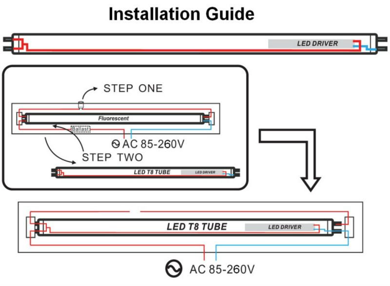
LED T5 Tube. • Installation instructions ... 25W LED T5 DW XXK 46”Double Input ... THE FOLLOWING BALLAST WIRING DIAGRAMS REPRESENT TYPICAL CONFIGURATION.3 pages
Description. Maxlite T5 wiring harness is the ideal solution for retrofitting a 4-lamp fluorescent T5 fixture with Type-B (ballast bypass) LED T5s. Each kit comes with pre-wired non-shunted G5 lampholders and a power quick connector to help reduce installation time and cost. Non-shunted G5 lamp holders pre-wired for fast and easy installation.
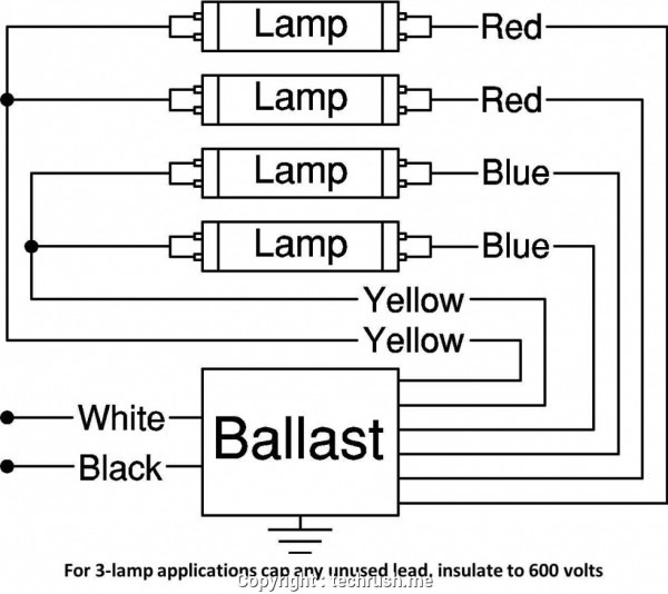
This diagram shows the basic wiring diagram for 6 bulbs, but you may be wiring . Wiring Diagram Detail: Name: Fulham Workhorse Ballast Wiring Diagram - 4 lamp t5 ballast wiring diagram b2network co in britishpanto rh britishpanto org connecting t5 ballast how to wire a t5 ho ballast.
Socket Wiring for T5 Linear Socket Wiring for T5 Twin Tube Correct - sockets wired in parallel Incorrect - sockets wired in series For ballasts that control more than one lamp, sockets wired to the yellow or blue-with-white stripe leads of the ballast must be wired in parallel,not in series. Typical 2-lamp installation Blue Yellow Note:Wired in ...
Wiring Diagram For Metal Halide Lights Inspirationa 1000 Watt - 4 - Ballast Wiring Diagram T8. Wiring diagram also provides beneficial suggestions for tasks that might need some extra gear. This book even contains ideas for added supplies that you might want as a way to end your tasks. It will likely be capable to offer you with further ...
Ok, as stated in the title of post and description a few times, the lamp (1 Circline lamp) is a T5. Ballast does indeed match the lamp according to its specs. The wiring diagram and only instructions they gave me in printed on the ballast ! lol Very very short instructions, hence the problem. I have it wired exactly as they say.
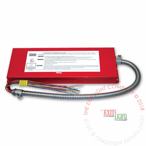
Select the proper voltage lead and cap the unused lead. When the XEB-T5-5-B is used with a switched fixture, the A.C. input to the emergency ballast must be connected ahead of the fixture switch. Refer to the figure below for switched and unswitched fixture wiring diagrams. INSTALLATION INSTRUCTIONS Figure 1 Figure 3 Ballast Wiring Block Diagram
T8/T5 Ballast Wiring Diagram available for reference online at EML Direct. All diagrams are available in PDF format for viewing on almost any device. Here you will find a selection of wiring diagrams for converting existing T5 and T8 fluorescent fittings to emergency operation using the ECK range of conversion kits.
Wiring diagrams and installation examples, page 7 EM T5 BASIC, 220 - 240 V 50/60 Hz T5 BASIC version ... Wiring Lamp/ballast/supply 8 - 9 mm wire preparation: 0.5 - 0.75 mm² ... This means, for example, in a linear T8 or T5 luminaire the mains wiring should be routed along one side of the luminaire body, while the wires












0 Response to "38 t5 ballast wiring diagram"
Post a Comment