38 6.2 glow plug controller wiring diagram
7 3 Glow Plug Wiring Harness - Wire Center • Regarding 7.3 Idi Glow - 7.3 Idi Glow Plug Controller Wiring Diagram. Wiring Diagram arrives with a number of easy to stick to Wiring Diagram Instructions. It's intended to help all of the average user in building a proper method. These instructions will likely be easy to grasp and implement. 3. Turn multi meter to amps or current flow setting. 4. Connect test leads between feed wire to each bank of glow plugs and to output terminal of glow plug controller/ relay. 5. Turn ignition switch to Run position to cycle glow plugs. Current reading should be 50-55 amps at each bank when cycling.
Zstar 110cc Atv Wiring Diagram; 1980 Volare Wiring Diagram; Pioneer Deh 4300ub Wiring Diagram; Ecg Placement Leads Diagram; Gm 10si Alternator Wiring; Lanzar Snv65i3d Wiring Diagram; 6.2 Glow Plug Controller Wiring Diagram; Supermicro X9scm-f Wiring Diagram; Recent Comments. Richy C. on Arduino uno dm542t wiring diagram

6.2 glow plug controller wiring diagram
A glow plug relay, or other standard relay, will have an isolated ground, with a 12V signal and a ground lug. Usually the control is from the ground lug, while the supply is either keyed hot, or always hot. Oh, and any relay that is for a starter relay, is not designed for constant current, even if it's wired correctly. Description: Glow Plug/controller Question – Page 2 – Diesel Place : Chevrolet for 6.2 Diesel Wiring Diagram, image size 640 X 416 px, image source : ww2.justanswer.com Description : 1983 Glow Plug Relay Wiring Diagram For 6.2L Diesel – Fixya pertaining to 6.2 Diesel Wiring Diagram, image size 415 X 300 px, image source : i.fixya.net Aug 09, 2011 · The Glow Plug Relay - Located on the left inner fender panel, provides current to the glow plugs as long as the thermal controller completes the ground circuit. The 6 Volt Glow Plugs--Used in This 12 Volt System - Are pulsed ON and OFF by the glow plug relay in response to messages received by the controller to prevent damage to the glow plugs.
6.2 glow plug controller wiring diagram. Wiring Diagrams 6.2 Glow Plug Controller Wiring Diagram [Archive] Glow System Contoller Location L Diesel. In your M the glow plug controller normally is located in a black box under For the wiring diagrams you should look at TM or TM I have an 86 Chevy Diesel with a L engine. The negative side of the glow plug relay (distributor) will not engage. See DB2 Handbook page 8-12 "Electrical- Glow Plug System" (pg 244/344) for a complete and thorough "OPERATION" description. In short.. "The glow plug controller electronic circuit operates the relay with cycling action that varies in length, based on the underhood air temperature and engine temperature sensed at its mounting bracket." 6.2 Glow Plug Controller Wiring Diagram Monday, April 26, 2021 Add Comment Edit. Get 6.2 Glow Plug Controller Wiring Diagram Images. Supply pump assembly (suction control valve). On my 2000 65 the glow plug controller has two terminals one goes into. Odd glow plug controller...-1984.jpg Images - Frompo from repairguide.autozone.com Of the wires on the two small terminals, the insulation color ... Joined Mar 13, 2008. ·. 3,949 Posts. #5 · Dec 11, 2009. on the drivers side there should be a wire on the front and rear glowplug and a rail from the front across each of them to the rear. on the pass side i cant be sure if there is two wires or not. but there should be a wire and then the rail across the plugs. U.
Glow Plug / controller Question Page 2 Diesel Place : Chevrolet for 6.2 Diesel Wiring Diagram is high definition wallpaper and size this wallpaper is 640x416. You can make Glow Plug / controller Question Page 2 Diesel Place : Chevrolet for 6.2 Diesel Wiring Diagram For your Desktop Background, Tablet, Android or iPhone and another Smartphone ... This is to me the best way to run your glow plugs for your GM 6.2 or 6.5 diesel engine. She fires right up every time and it allows you to control how long ... the glow plug controller is usually in the rear top of the passenger head, the fast idle/cold advance is usuall in the rear, side of the passenger head, and on some of the newer ones it moved to the coolant crossover. I may have got the head positions for each reversed, but it will give you the idea of what to look for Riddle_3d Registered Dec 19, 2010 · 2. Ran a wire from each side of the two main screw terminals (which are toward the front on the glow plug relay) to the terminals of the solenoid/relay. 3. Ran a wire from the solenoid/relay's controlling terminal to a lighted switch under the dashboard that goes to a positive lead from the lighter.
6.2 glow plug controller wiring diagram. 25 Jan 2013 — 1983 K5 6.2 L, i have all the Diesel Page books and bought the new ... you'd need a new glow plug wiring harness made for the 1985-93 glow... The Glow Plug Relay - Located on the left inner fender panel, provides current to the glow plug s as long as the thermal controller completes the ground circuit. The 6 Volt Glow Plug s--Used in ... The one piece glow plug controller of 85+ on the 6.2 was actually a very simple unit. Here's a wiring diagram of how the controller is wired. However where is says "glow plugs 6 volt" is wrong. The glowplugs are 10.5 volts each, not 6 volts. the 6.2 and 6.5 never used 6 volt glowplugs, ever. Pin E is ground for the relay. A video describing my newly installed glow plug override on The Hulk (my green 1990 suburban) 6.2/6.5 glow plug controller diagram I need a wiring diagram for 6.2/6.5 glow plug controller - Cars & Trucks question
6.2 Diesel Manual Glow Plug Conversion
Basically you need to either activate a relay (ford starter solenoids are common, but older 6.2 relays will work), or you need to wire a switch (one that can handle the power, like the ones used in race car ignitions) between the battery and the glow plug controller. I hope this helps.

6 5 Diesel Glow Plug Wiring Diagram - Wiring Diagram Networks
63. Location. OKC, OK. The easiest way to work on a CUCV electrical issue is to copy and paste the wiring diagram you need from the TM, save it to your computer, And then color the circuit you are working on. I use MS Paint. Don't know how to read the diagrams? Then read the first few pages of the Troubleshooting section of the -20 or -34 manual.
2002 6.6 duramax engine glow plug timer wiring schematic ...
25 Jan 2013 — 1983 K5 6.2L, i have all the Diesel Page books and bought the new ... you'd need a new glow plug wiring harness made for the 1985-93 glow ...
Ford Glow Plug Controller Wiring Diagram For 1993 - Wiring ...
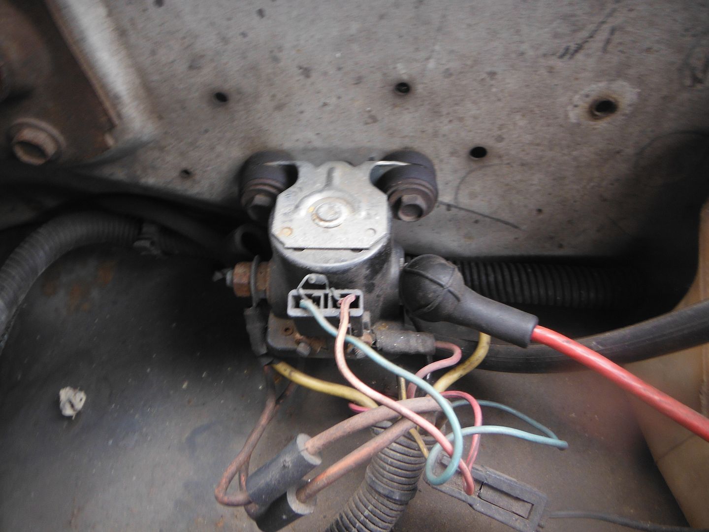
The two-prong switch used in many 6.2 diesel glow plug systems is the "inhibit switch." It has two prongs on top and there is full continuity between them until the switch reaches a temp of 125 degree F. Then it opens and prevents the glow plugs from working. Easy to buy, easy to replace, and easy to do without.
65 Glow Plug Controller Wiring Diagram - Derslatnaback
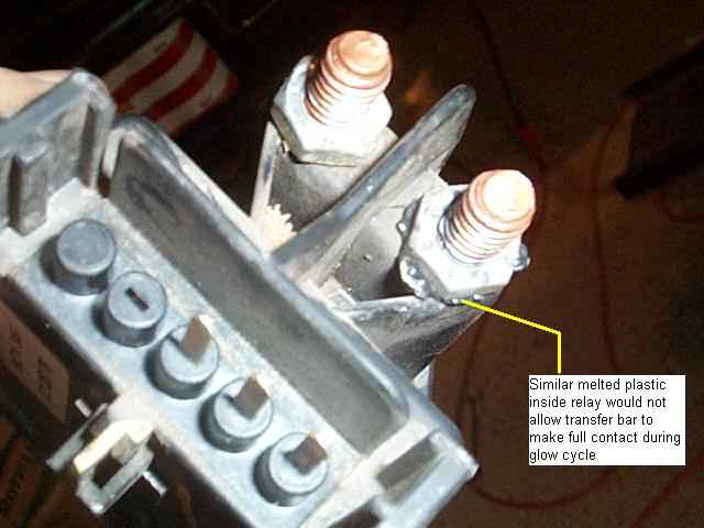
Replace any wires or connectors that are burned, melted, or otherwise bad. • Relay chatter coming from the glow plug controller (glow plugs cycling on-and-off ...

Need pinout for 6.2 glow plug controller | K5 BLAZER NETWORK
Bucking 208v To 240v Wiring Diagram; Ford 7.3 Apps Wiring Diagram; 6.2 Glow Plug Controller Wiring Diagram; Sony Cdx-gt640ui Wiring Diagram; Swm 5 Lnb Wiring Diagram; D7412 Wiring Diagram; Fahrenheat Model # Fssho4004 Wiring Diagram; Miller 115/240 Wiring Diagram; Show Me The Wiring Diagram For The Bushnell 1250 Flashlight; Slo Syn Motor Wiring

62 Diesel Wiring Diagram
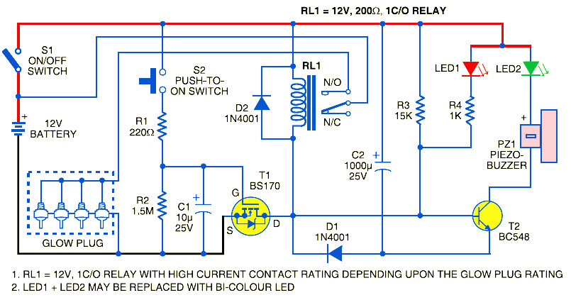
The controller pulses 24v to the 12v glow plugs to avoid overheating and damaging the plugs. If they are cycled at 50% with 24v it would be approximately the same as running them 100% at 12v. This means simply using a momentary contact push button switch, a solenoid and holding it on would likely overheat them each time.

Round open neon
I copied this from my GM service manual for 1982 6.2 diesel. 1. If the glow plug relay is not clicking on and off then turn the ignition to the RUN position and connect a 12V test light to ground and touch the pink/black wire in the glow plug relay connector. 2.

35 6.5 Glow Plug Controller Wiring Diagram - Wiring ...
6.2 Glow Plug Controller Wiring Diagram Source: image.slidesharecdn.com 6.2 Glow Plug Controller Wiring Diagram Source: www.dieselhub.com Read electrical wiring diagrams from negative to positive and redraw the signal being a straight line.
1984 Chevy K10 Wiring Diagram - Wiring Diagram
My own design for a glow controller for my 1988 Late style factory glow controller.
1995 6.5T Glow Plug Fuse Dead ODB1 - Diesel Bombers
Oct 09, 2018 · 10.09.2018. 10.09.2018. 0 Comments. on 6.2 Glow Plug Controller Wiring Diagram. Check that the four-wire connector at the controller is seated properly and latched . Tighten the 1: Glow plug system schematic, (L). Click image to see. [IMG] Does anyone have a pinout for the glow plug controller? links on their website that you can download ...

my 87 6.2 diesel..glow plug light..engine wont start ...
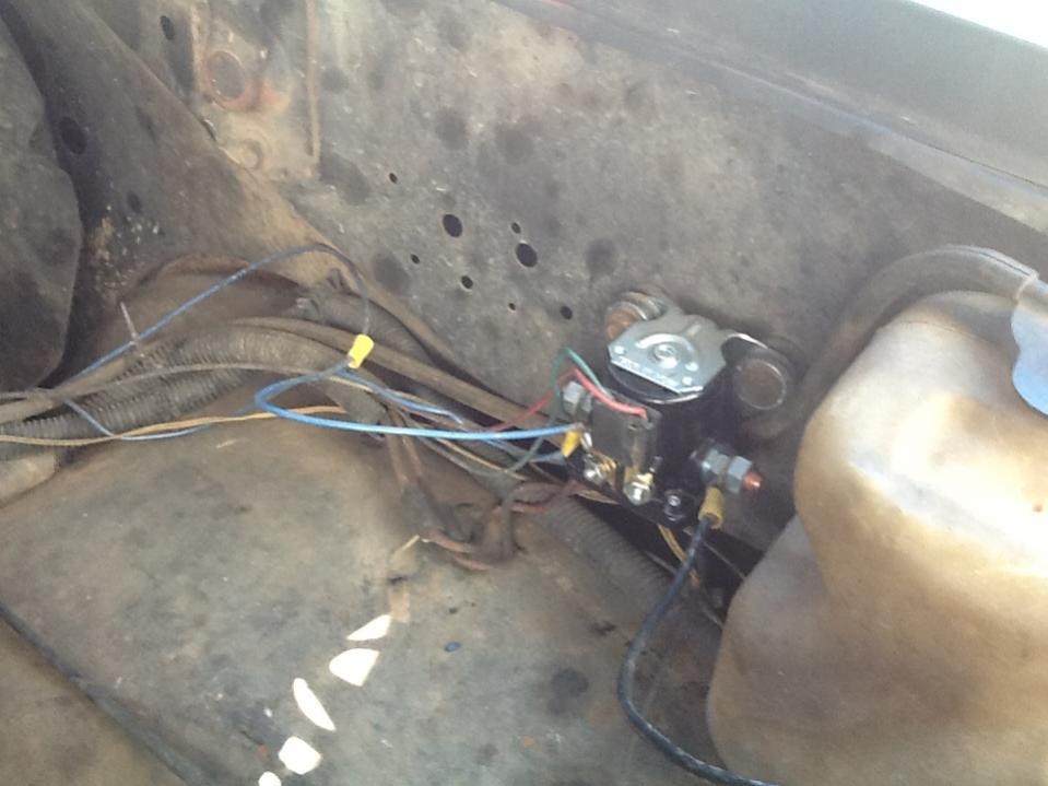
the Glow plug relay that sits at the rear of the intake manifold is what controls the fast idle and the glowplugs timing etc, this relay is prone to failure, and thus most guys just wire the glow plugs up to a relay or Starter solonoid, that is controled by a push button on the dash. thus problems solved, the glow plugs wiring (green) come together and turn into a (red) (i think) and bolt to ...

6.2 Glow Plug Controller Wiring Diagram - Database ...
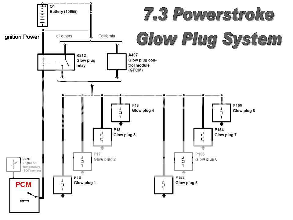
The glow plug control unit uses a glow plug relay to switch the current for the glow plugs on and off. The more glow plugs monitored by a control unit, the higher the current the circuit will need. To reduce the current needed, glow plugs are often distributed across two circuits, with two glow plug relays.

My 1984 GM 6.2 diesel pick up does not have any power ...
6.2 Glow Plug Controller Wiring Diagram from forum.ih8mud.com To properly read a cabling diagram, one offers to know how the particular components in the method operate. For instance , when a module is usually powered up and it also sends out a new signal of fifty percent the voltage and the technician would not know this, he'd think he has a challenge, as he would expect a 12V signal.
6.2 diesel glow plug relay LOUD - Diesel Bombers
6.2 Glow Plug Controller Wiring Diagram from forum.ih8mud.com Print the electrical wiring diagram off plus use highlighters to be able to trace the circuit. When you employ your finger or perhaps follow the circuit with your eyes, it’s easy to mistrace the circuit.

Taken in Heals, London
5a220 ford glow plug relay wiring harness the 6 2 liter diesel engine 4runner starter wiring diagram the 6 2 liter diesel engine ez 4505] mercedes glow plug relay wiring diagram free diagram 7 3l idi automatic to manual the 6 2 liter diesel engine kr 7628] ford 7 3 glow plug relay wiring diagram moreover 7 wrg 4671] 7 3 diesel engine diagram 4runner starter wiring diagram
31 6.2 Glow Plug Controller Wiring Diagram - Wiring ...
Installed this on a 1986 Chevy D-30 M1008 with a 6.2 Diesel. Works mint. Subscribe for more videos

My 1984 GM 6.2 diesel pick up does not have any power ...
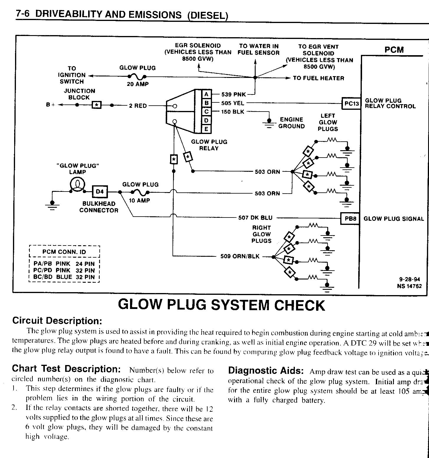
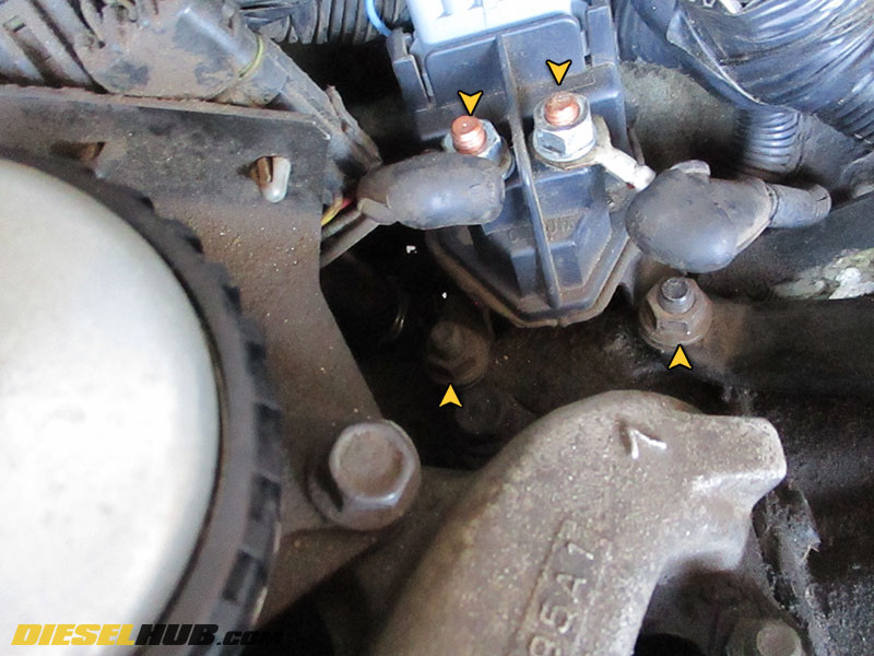
Check the glow plugs. Most 6.2 L diesels came with one relay but early models had two. Test the glow plugs by unplugging the electrical connection from a glow plug. Hook up an ohmmeter to the glow plug terminal and ground the other end. The resistance should read between 0.8 and 2 ohms, depending on the glow plug type.
Unplugged black cord
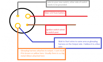
3.Terminal C connects to the light blue wire from terminal 3 of the old glow plug controller that has been connected the two black wires from terminal 5 and 6 of the old glow plug controller. 4.Terminal D connects to the main wiring harness and receives power when the ignition switch is in the ON position. 5.Terminal E is grounded to the chassis.

35 6.5 Glow Plug Controller Wiring Diagram - Wiring ...
Repair guides wiring diagrams autozone com and 6 2 diesel diagram. 62 glow plug controller wiring diagram. I found a wiring diagram for a manual glow plug setup. 6 2 diesel glow plug wiring welcome to our site this is images about 6 2 diesel glow plug wiring posted by alice ferreira in 6 category on sep 12 2019.
27 6.5 Glow Plug Controller Wiring Diagram - Wiring ...
Aug 09, 2011 · The Glow Plug Relay - Located on the left inner fender panel, provides current to the glow plugs as long as the thermal controller completes the ground circuit. The 6 Volt Glow Plugs--Used in This 12 Volt System - Are pulsed ON and OFF by the glow plug relay in response to messages received by the controller to prevent damage to the glow plugs.

Costume red neon
Description: Glow Plug/controller Question – Page 2 – Diesel Place : Chevrolet for 6.2 Diesel Wiring Diagram, image size 640 X 416 px, image source : ww2.justanswer.com Description : 1983 Glow Plug Relay Wiring Diagram For 6.2L Diesel – Fixya pertaining to 6.2 Diesel Wiring Diagram, image size 415 X 300 px, image source : i.fixya.net

6.2 Diesel Wiring Diagram - Wiring Diagram And Schematic ...
A glow plug relay, or other standard relay, will have an isolated ground, with a 12V signal and a ground lug. Usually the control is from the ground lug, while the supply is either keyed hot, or always hot. Oh, and any relay that is for a starter relay, is not designed for constant current, even if it's wired correctly.

Elegant chandelier

65 Glow Plug Controller Wiring Diagram - Wiring Diagram
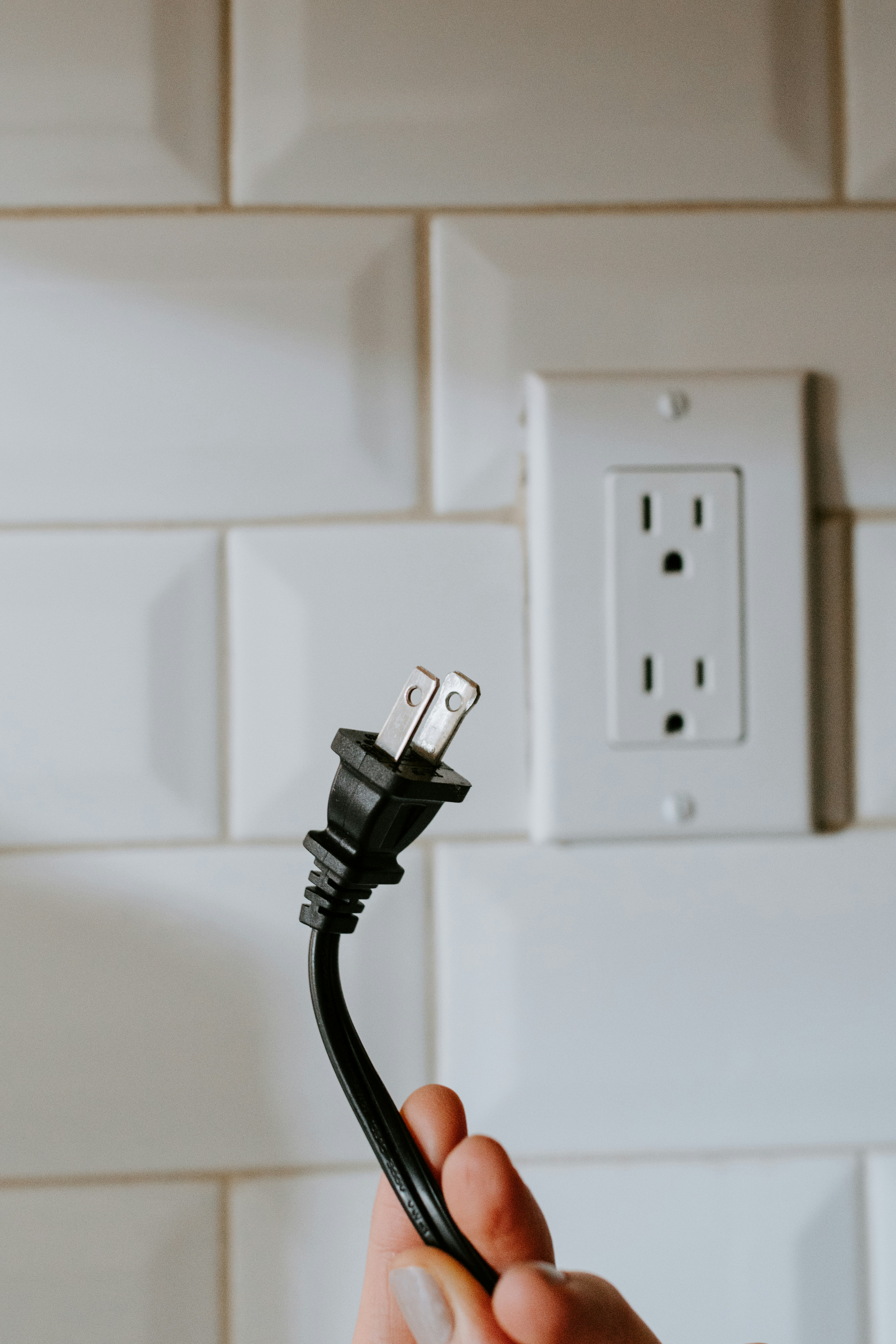
Hand plugging a white cord into an outlet
HELP! HJ45 Glow Plug Controller heating too fast | Page 4 ...

Xbox One S controller
![[DIAGRAM] 6 5 Diesel Glow Plug Relay Wiring Diagram FULL ...](https://cimg6.ibsrv.net/gimg/www.ford-trucks.com-vbulletin/922x642/80-presentation1_b08ee99b542be4650695c0e5f133042b5c9bd974.jpg)
[DIAGRAM] 6 5 Diesel Glow Plug Relay Wiring Diagram FULL ...

Wiring Diagram For Glow Plug Relay 73

35 6.5 Glow Plug Controller Wiring Diagram - Wiring ...

jawfox photography

Need to create a highlite texture map, for a project I was working on for Sony PlayStation. So I spray painted a brand new controller. After the project was complete I had these extra shots I did not use, in the spirit of Unsplash I decided to upload them.
How do you test the GP controller. - Diesel Bombers

27 6.2 Glow Plug Controller Wiring Diagram - Wiring ...
6 5 Diesel Glow Plug Wiring Diagram - Wiring Diagram Networks

6 9 Diesel Engine Diagram - Wiring Diagram Networks

Ford Glow Plug Controller Wiring Diagram For 1993 - Wiring ...
0 Response to "38 6.2 glow plug controller wiring diagram"
Post a Comment