36 fuel oil piping diagram
cargo, steam and water ballast piping, including pipes located on deck, in the pump room, cofferdams, pipe tunnel(s) and void spaces. Particular attention is given to: •Inert gas piping to verify the absence of corrosion and gas leakage. A test under working conditions is arranged. •The crude oil washing system and its fittings. •The pump ... MFC Series Gas & #2 Fuel Oil Supply Design Guide Page 4 of 14 AERCO International, Inc. • 100 Oritani Dr. • Blauvelt, NY 10913 TAG-0078_0D 2/28/2018 Ph.: 800-526-0288 GF-148-G 2.2 Gas Pressure Requirements AERCO MFC boiler with Riello burner requires a stable gas and propane input.
vent piping, fill piping, etc.), be equipped with means for controlling the filling operations. o NFPA 37 (6.6.2) requires that engine-mounted Class II fuel tanks be filled by closed piping systems. Generator subbase diesel tanks ("belly tanks") appear to fall under this requirement.

Fuel oil piping diagram
Fuel Oil Piping Diagram for Main Tank, Day Tank, and Diesel Genset. Fuel Oil Piping Diagram for Main Tank, Day Tank, and Diesel Genset. Fuel oil systems design has always been a challenge for most designers. It involves thorough knowledge of NFPA codes, EPA regulation, local and state laws, and client requirements. fuel oil to diesel is to in pipe specifica71t* oss-e4a a. 2'. n-rj 1/2* n-rj e. cp with a to tx xØØØl set nessi.Æ psig ax ftÆl ort so 1/2- to fl.-el on- ecircu-at1œa 2 oil rev. per oe-6345 ed. c. 11 0.6 retired exe>ptic date cate cate civil elec. oconee a istec rture condition 1 power nuclear station units 1, 2 & 3 flow diagram of fuel ... This technical manual contains copyrighted material DEPARTMENTS OF THE ARMY AND THE AIR FORCE WASHINGTON 26, DC., 5 September 1966 TM 55-4018-1/TO 88G1-6-21 is published for the use of all concerned.
Fuel oil piping diagram. Fuel oil piping shall be tested in ac-cordance with NFPA 31. SECTION 1309 OIL TANKS FOR ONE- AND TWO-FAMILY DWELLINGS AND TOWNHOUSES 1309.1 Materials. Supply tanks shall be listed and labeled and shallconformtoUL142forabove-groundtanks,UL58forun-derground tanks and UL 80 for inside tanks. When designing fuel oil systems, remember the following: Provide foot valves (to maintain pump prime), anti-siphon valves (to prevent accidental leakage), and fusible link shutoff valves (for fire safety). When calculating pump suction lift, assume the worst-case scenario (i.e., a nearly empty tank). Oil Tanks and Piping Chapter 3 Chapter 3—Oil Tanks and Piping 3-3 Introduction The comfort, cleanliness and efficiency of today's oilheat systems rely on clean, uncontaminated fuel reaching the oilburner. To achieve this: • Install tanks properly. • Maintain tanks by regularly inspecting them and fixing minor defects before SECTION VIII DIAGRAM OF PIPING. 40.The contractor installing the fuel oil equipment shall furnish copies of diagrams showing all of the main oil lines and controlling valves, and these .diagrams ...
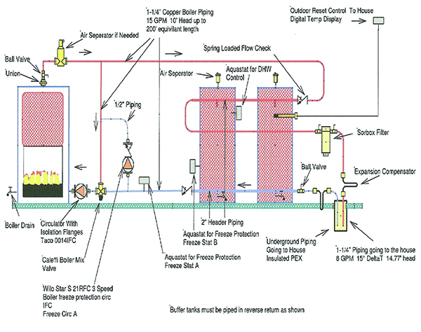
I. PIPING DIAGRAMS Figure 6 . 23 LP- 276 REV. 3.28.14 Figure 7 NOTES: 1. This drawing is meant to demonstrate system piping concept only. Installer is responsible for all equipment and detailing required by local codes. 2. Boiler circulator(s) must be rated for open loop applications. Do not use cast-iron circulators. 8.4 Fuel Return Piping. A return line from a burner or pump to a supply tank shall have no valves or obstructions and shall enter the top of the same tank. 8.5 Supply Piping to Oil-Burning Appliances. 8.5.1 All piping shall be connected into the top of the supply tank. Where two tanks are cross- To speak to a Preferred engineer who knows NFPA fuel codes and is experienced with fuel oil storage and handling systems, call (203) 743-6741. INSTRUCTIONS The goal is to select a pump that meets the flow and pressure requirements of your project, and design the piping system so that the suction on the pump inlet, and discharge pressure at the ... Installations should avoid putting fuel oil where it is exposed to temperature extremes. The pour point limit for #1 and #2 fuel oils not seasonally-adjusted is 0 o F and 20 F, respectively LENGTH OF RUN (L) The length of piping from tank to fuel unit is calculated using the following
B. Handle fuel oil system components carefully to avoid damage to material component, enclosure and finish. C. Store fuel oil system components in a clean, dry space and protect from the weather. PART 2 - PRODUCTS 2.1 PIPE AND FITTINGS: A. Fuel Oil Piping Buried Below Ground: 1. pressure of the ANSI/ASME B16.5 piping system flanges at 100 degrees F (38 degrees C), see Table 1. Test hydrant and direct aircraft fueling systems and installation fuel pipelines with fuel that will be used in the pipeline or, at a minimum, a fuel with the same minimum specification flashpoint as the fuel that will be used when the piping is in The fuel oil system for a marine diesel engine can be considered in two parts—the fuel supply and the fuel injection systems. Fuel supply deals with the provision of fuel oil suitable for use by the injection system. Marine Fuel oil system includes various piping systems provided for bunkering, storage, transfer, offloading and treatment of ... 1301.4 Fuel Tanks, Piping and Valves. The tank, piping and valves for appliances burning oil shall be installed in accordance with the requirements of this chapter. Where an oil burner is served by a tank, any part of which is above the level of the burner inlet connection and where the fuel supply line is taken from the top of the tank, an ...

30 Fuel Oil Piping Diagram - Wire Diagram Source Information
Fill and Product Piping Connections to Domestic Storage Tanks: The fill pipe material shall be 2 in (50 mm) schedule 40 black steel. Threaded joints in the fill piping shall be made fuel oil-tight using joint compound conforming to CAN/ULC-S642-M, Compounds and Tapes for Threaded Pipe Joints, or equivalent.

32 Fuel Oil Tank Installation Diagram - Wiring Diagram List
Natural Gas and Liquefied Petroleum Gas Burner and Igniter Fuel Standard Piping Diagram: PDF. SD235239-04: No. 2, 5 & 6 Burner Fuel Oil Systems Standard Piping Diagram : PDF. SD236400-01: Air cooled chiller - piping connections: PDF. SD236400-02: Water cooled chiller - piping connections: PDF. SD236500-01:

Image from page 223 of "American engineer and railroad journal" (1893)
that is found in the building. Storage tanks and buried piping will not be addressed. Description of a modern diesel fuel system as a standby energy source. The modern diesel fuel or fuel oil systems are used differently than systems designed a decade or more ago. In early fuel oil system designs, boilers were the primary user of the fuel. The ...
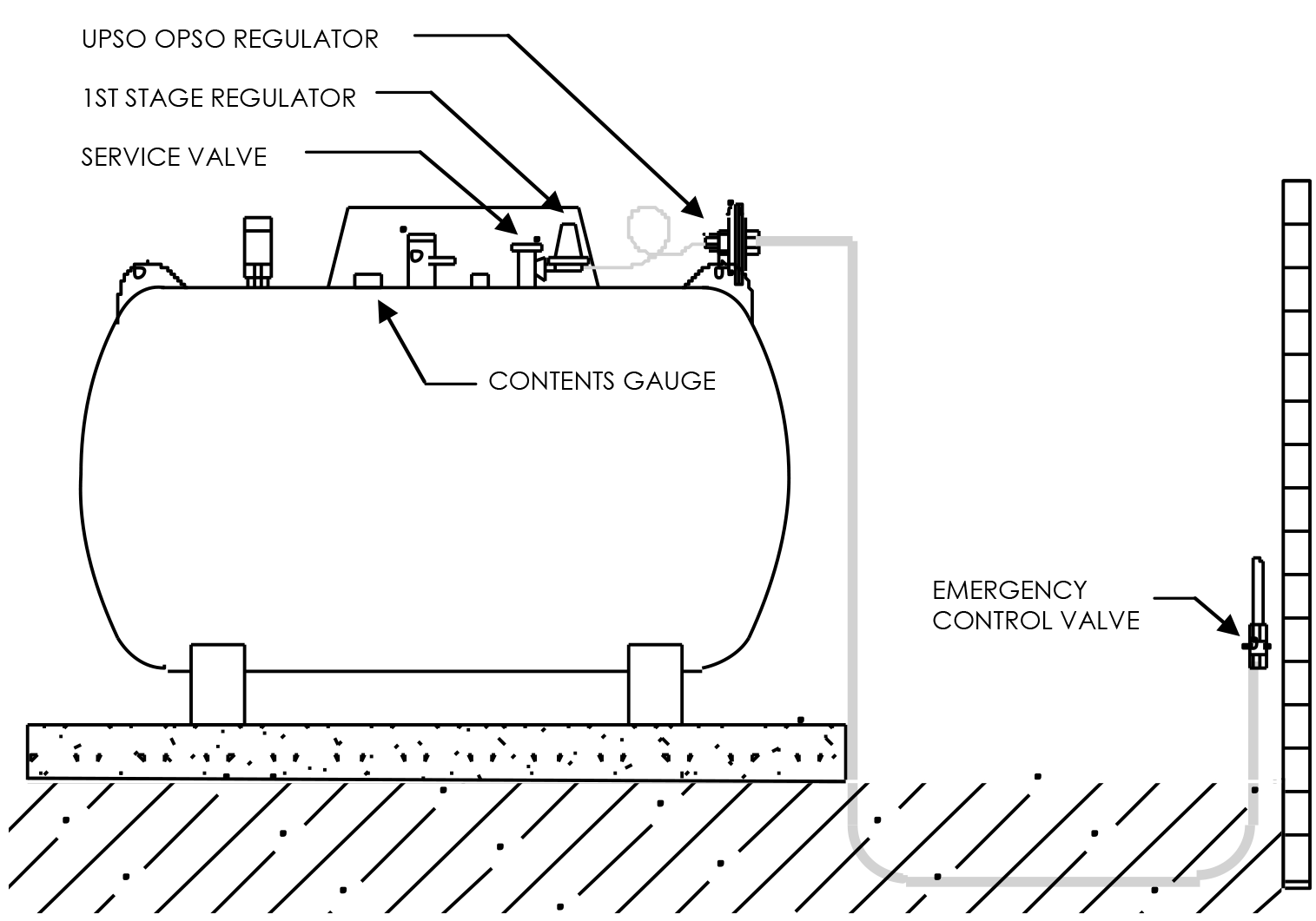
LPG Gas Frequently Asked Questions
OPW FlexWorks Fuel Oil Piping Systems are designed to provide a reliable, secondarily contained, underground fuel supply system to generators and boilers from remote fuel tanks. Typical applications include a 3/4" or 1" supply and a 1" overflow return line running from a remote AST or UST to a generator engine or boiler Day Tank.

Fuel Oil Piping Diagram - Free Wiring Diagram
burner oil piping can be found in Table 6 this page, Figure 11 on page 12, and Figure 12 on page 13. It is very important to properly size the oil suction line and oil filter, to provide fuel flow to the burner without exceeding 10" suction pressure (vacuum) at the oil pump suction port. The method to properly size copper tubing is outlined

Marine and Oil&Gas Piping Construction: PROCESS AND PIPING ...
fuel oil storage tank in a separate room located at a building level above the diesel room. There is no elevated fuel oil piping adjacent to the engine. The fuel oil piping between the day tank and the engine drops down from the tank and runs below the elevation of the engine until it reaches the engine. The transfer pumps and auxiliary

Radiant / baseboard mechanic room piping layout / design ...
1303.1 Approval. Joints and connections shall be approved and of a type approved for fuel-oil piping systems. Threaded joints and connections shall be made tight with suitable lubricant or pipe compound. Unions requiring gaskets or packings, right or left couplings, and sweat fittings employing solder having a melting point of less than 1,000 ...

Scythian Messengers Meet the Persian King Darius I by Franciszek Smuglewicz. Creation Date: end of the 18th century - beginning of the 19th century. Provided by Lithuanian Art Museum. PD for Public Domain Mark
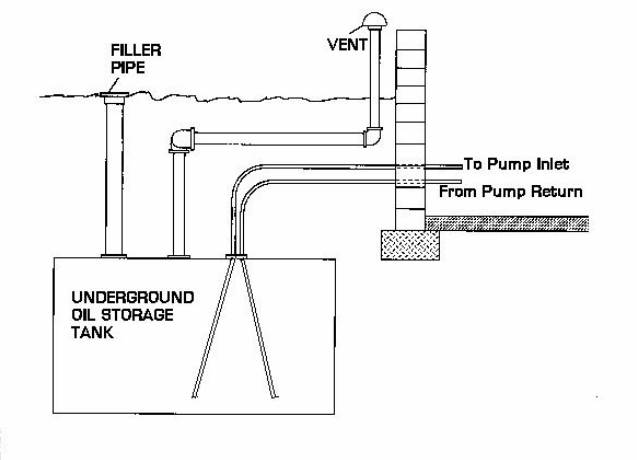
The fill and vent piping for oil storage tanks must be of adequate diameter (typically 2" filler and 1.5" to 2" vent though older tanks may use 1 1/4" vents), Properly located (vent not too distant from filler), and. Protected against water entry or insect nest blockage of the vent line.

30 Fuel Oil Piping Diagram - Wire Diagram Source Information
Preferred Inc. has a good pamhlet on fuel oil piping. It discuss (2) way of arranging the return - either direct back to tank or direct back to the supply where it can feed downstream boilers. Main pump sizing for each is different. Note that burner pumps circulate twice or more rhe actual boiler maximum firing rate.
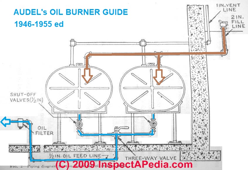
Oil Piping for Duplex or Paired Oil Storage Tanks
No.2 Burner Fuel Oil Systems, Burner Fuel Oil Systems - Standard Piping Diagram Author: Department of Veterans Affairs, Office of Construction and Facilities Management, Facilities Standards Service Subject: standard detail Created Date: 8/5/2021 6:34:18 PM

30 Fuel Oil Piping Diagram - Wire Diagram Source Information
ground fuel oil tanks. 1305.4 Return piping. Return piping shall connect to the top of the fuel oil tank. Valves shall not be installed on return piping. 1305.5 System pressure. The system shall be designed for the maximum pressure required by the fuel-oil-burning appli-ance. Air or other gases shall not be used to pressurize tanks. 1305.6 Fill ...
Oil Boiler: Oil Boiler Piping Diagram
This technical manual contains copyrighted material DEPARTMENTS OF THE ARMY AND THE AIR FORCE WASHINGTON 26, DC., 5 September 1966 TM 55-4018-1/TO 88G1-6-21 is published for the use of all concerned.

Pipe connection between natural gas and fuel gas line ...
fuel oil to diesel is to in pipe specifica71t* oss-e4a a. 2'. n-rj 1/2* n-rj e. cp with a to tx xØØØl set nessi.Æ psig ax ftÆl ort so 1/2- to fl.-el on- ecircu-at1œa 2 oil rev. per oe-6345 ed. c. 11 0.6 retired exe>ptic date cate cate civil elec. oconee a istec rture condition 1 power nuclear station units 1, 2 & 3 flow diagram of fuel ...
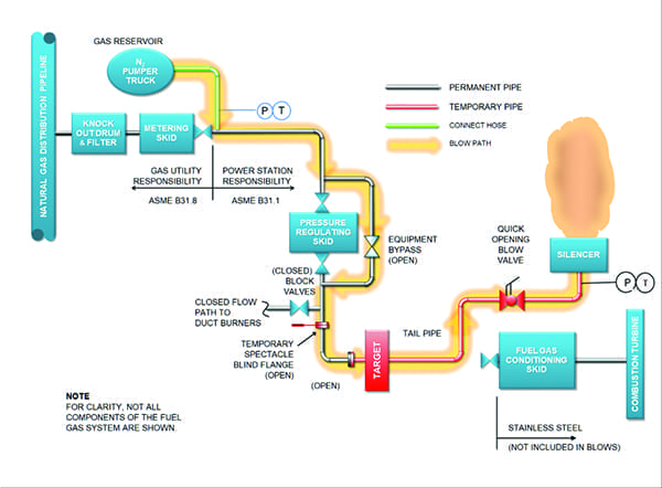
How to Clean Natural Gas Piping with Gas Blows
Fuel Oil Piping Diagram for Main Tank, Day Tank, and Diesel Genset. Fuel Oil Piping Diagram for Main Tank, Day Tank, and Diesel Genset. Fuel oil systems design has always been a challenge for most designers. It involves thorough knowledge of NFPA codes, EPA regulation, local and state laws, and client requirements.

Fuel Oil Tank Installation Diagram - General Wiring Diagram
Residential Boiler Piping Diagram - Hanenhuusholli
30 Fuel Oil Piping Diagram - Wire Diagram Source Information
Heating Oil Tank & Piping Sludge Prevention or Cures Oil ...

The White Apple Tree by Antanas Samuolis. “The White Apple Tree†by Expressionist painter Antanas Samuolis occupies a special place in the history of Lithuanian fine arts, as one of the most powerful pieces in the landscape genre. Provided by Lithuanian Art Museum. PD for Public Domain Mark

Fuel Oil Piping Diagram - Atkinsjewelry
AC-004 Instruction Manual
32 Fuel Oil Tank Installation Diagram - Wiring Diagram List

Gas pipe sizing--summation method Q — Heating Help: The Wall

aux boiler piping with storage question about Caleffi ...
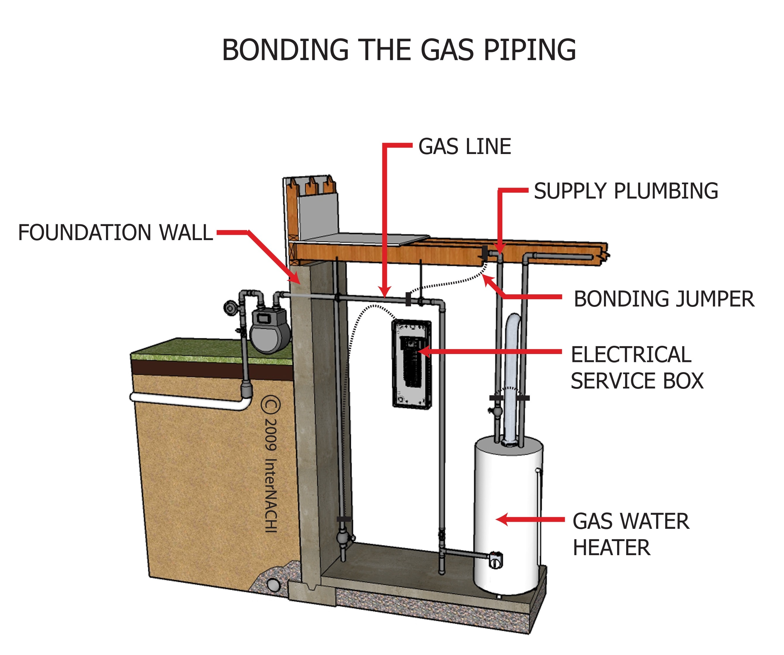
Bonding the Gas Piping - Inspection Gallery - InterNACHI®

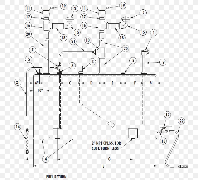
Figure 2-9. Fuel oil system piping diagram.

A30000 FUEL PIPING FUEL SYSTEM EPC Kubota online
/d_safetyinternalbrand/jurisdictionalpipe.png)
Natural Gas Pipeline Safety | National Grid

Fuel Oil Piping Diagram - Free Wiring Diagram

Fuel Oil Piping Diagram - Atkinsjewelry

industrial valves manufacturers industrial valves market ...

Attention:Phil Gas Piping Calculation

aux boiler piping with storage question about Caleffi ...

Nuns. Creator: Nesterov, Michail VasiljeviÄ. Date: 1893. Institution: Slovak National Gallery. Provider: Slovak National Gallery. Providing Country: Slovakia. PD for Public Domain Mark
Fire Pump Storage Tank Diesel Fuel Piping And ...

marine engineering: ENGINE ROOM PHOTOS AND COMPONENTS (PART 2)
0 Response to "36 fuel oil piping diagram"
Post a Comment