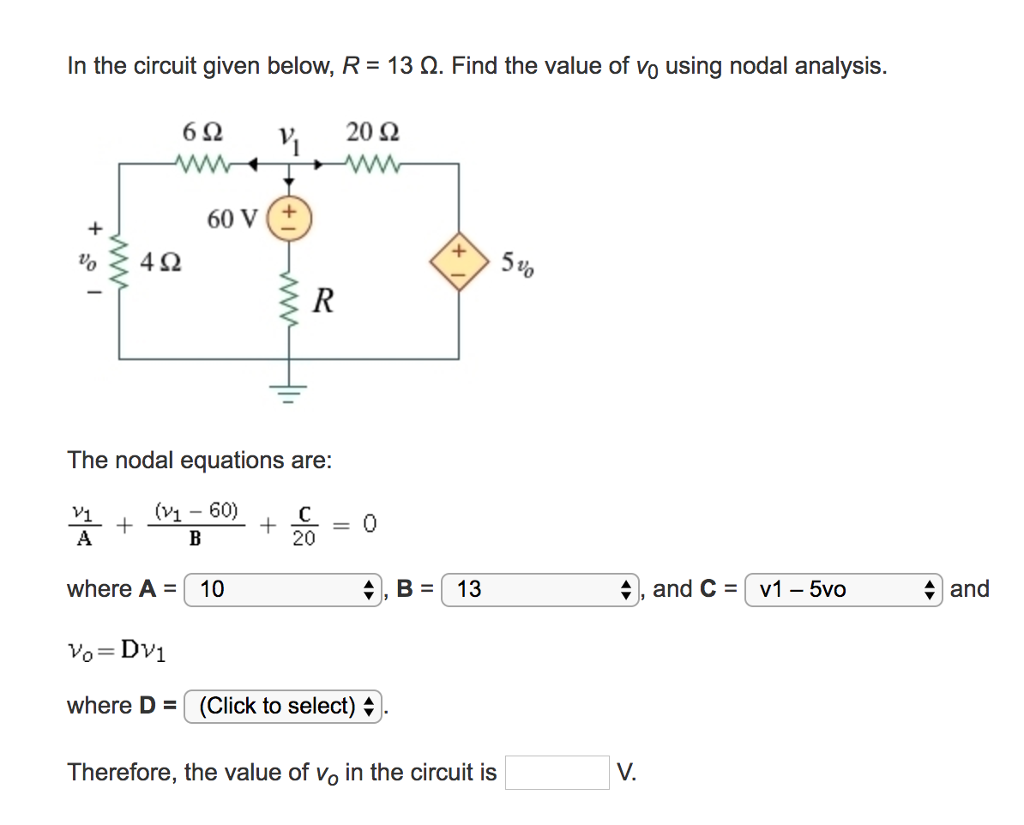
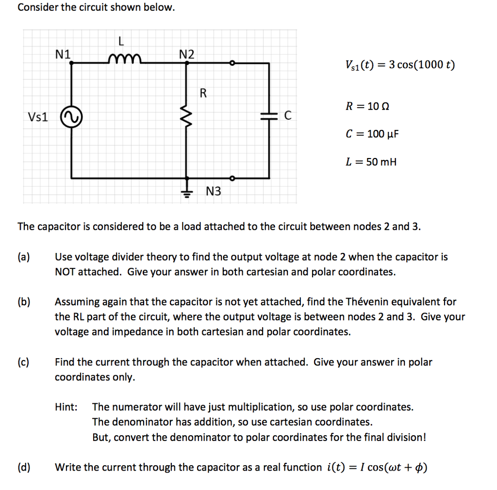
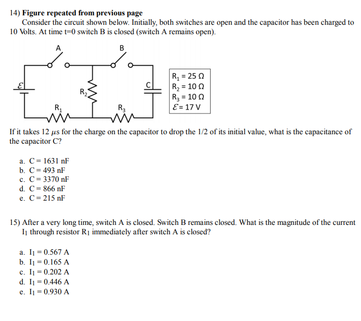
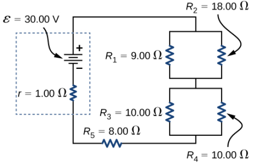
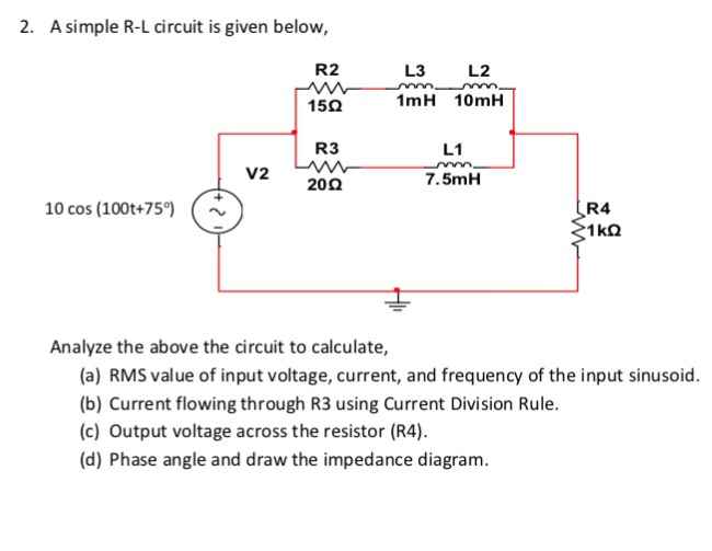
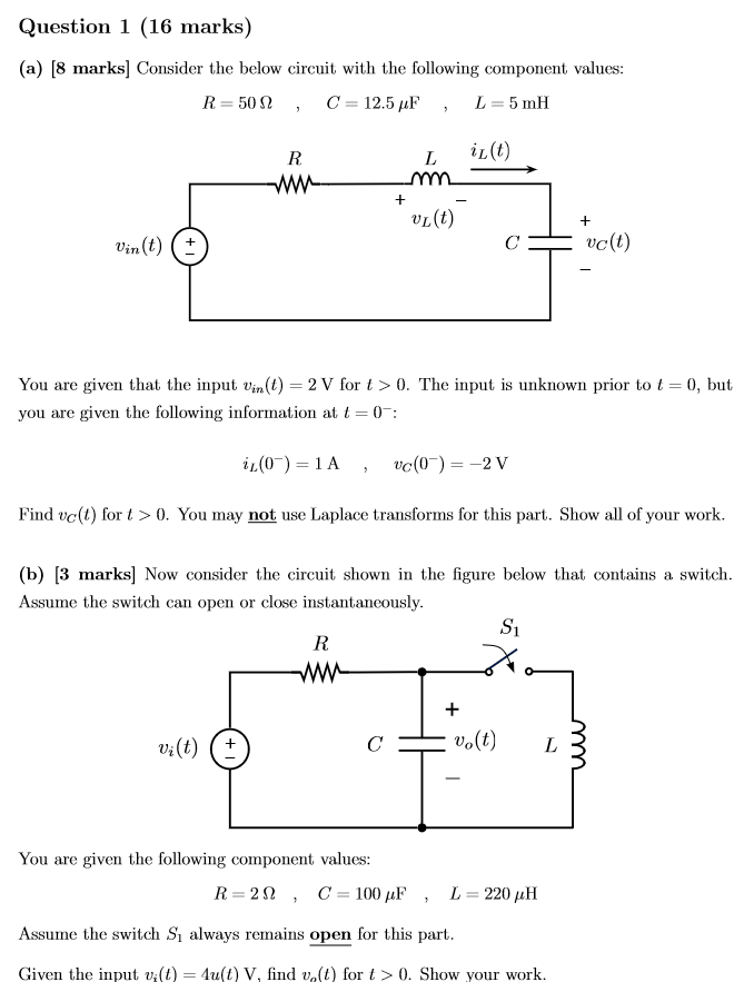
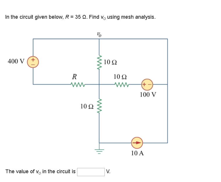
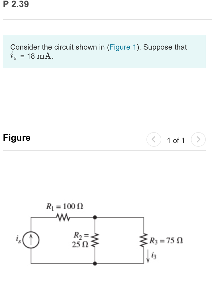
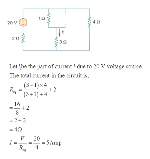
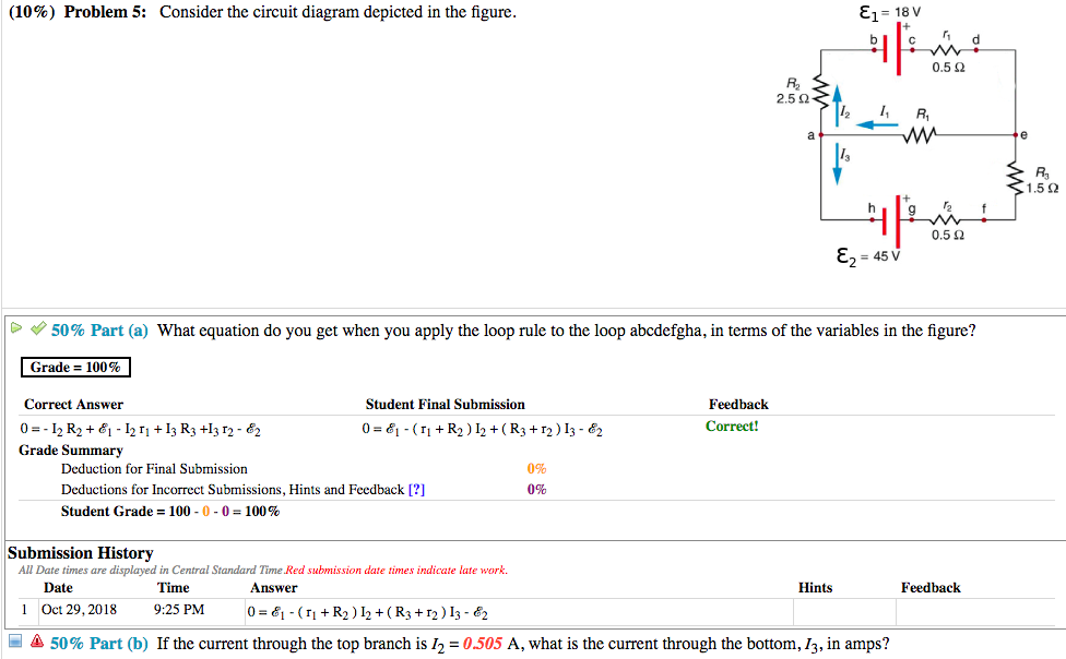
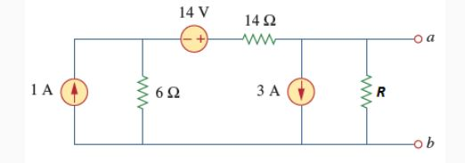
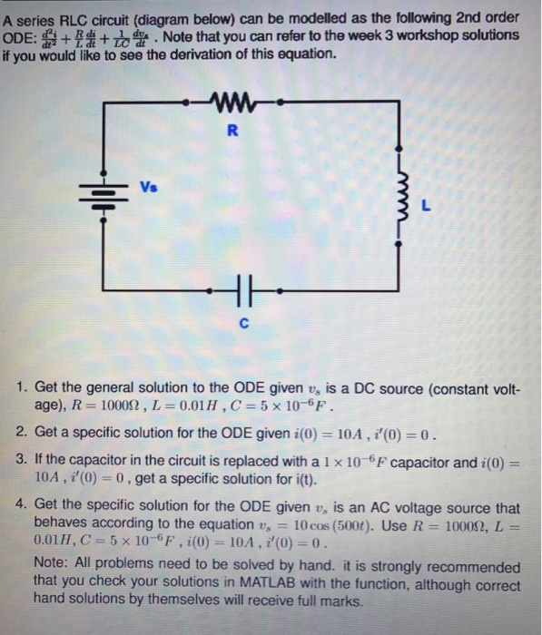
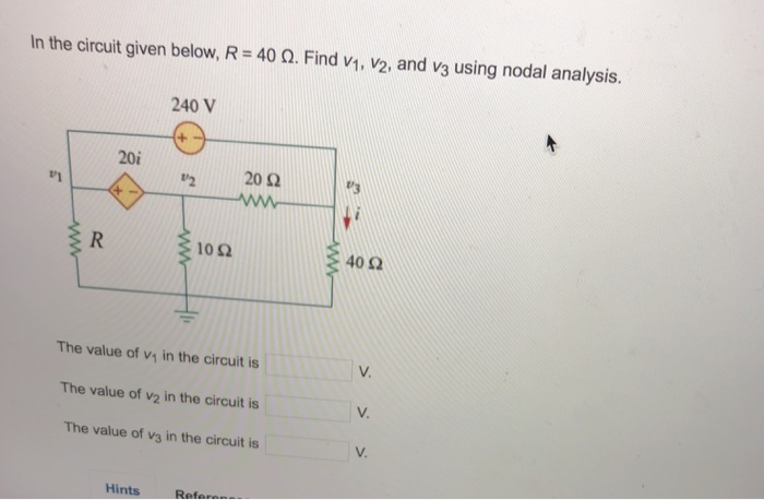
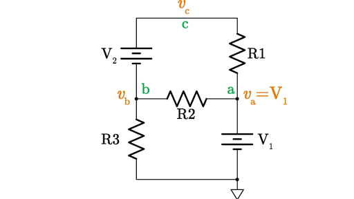
36 consider the circuit in the diagram below, in which r = 13 ω.
Generally, when constructing a phasor diagram, angular velocity of a sine wave is always assumed to be: ω in rad/sec. Consider the phasor diagram below. Phasor Diagram of a Sinusoidal Waveform As the single vector rotates in an anti-clockwise direction, its tip at point A will rotate one complete revolution of 360 o or 2π representing one complete cycle. For a parallel circuit, the R eq value is always less than the smallest of all the resistor values. Use the diagram below at the right in order to answer questions. PSYW 13. Determine the equivalent resistance of the circuit at the right. 1/R eq = (1/5 Ω) + 1/(4 Ω) + 1/(7 Ω) = 0.5928 … Ω R eq = 1/(0.5928 … Ω) = 1.69 Ω (1.6867 …Ω) 14.
Consider a circuit with a cell and an ohmic resistor, R. If the resistor has a resistance of \(\text{5}\) \(\text{Ω}\) and voltage across the resistor is \(\text{5}\) \(\text{V}\), then we can use Ohm's Law to calculate the current flowing through the resistor.

Consider the circuit in the diagram below, in which r = 13 ω.
m m 6000 6000 3 16 16 3 v R R v + = ⇒= − (a) The voltage measured by the meter will be 4 volts when R = 6 kΩ. (b) The voltage measured by the meter will be 2 volts when R = 1.2 kΩ. P 4.3-9 Determine the values of the node voltages of the circuit shown in Figure P 4.3-9.. Figure P 4.3-9 . Solution: Express the voltage source voltages as functions of the node voltages to get Pharmacological Basis For Nursing Interventions II (NUR 3192) Computer Information Systems (CIS 401) Human Anatomy (ANP 300) Introduction to Organic and Biological Chemistry (CHEM120-62398) The radio has a. 3.20 Ω. 3.20 Ω resistance. (a) Draw a circuit diagram of the radio and its battery. Now, calculate the power delivered to the radio (b) when using a nicad cells, each having an internal resistance of. 0.0400 Ω. 0.0400 Ω, and (c) when using an alkaline cell, having an internal resistance of. 0.200 Ω.
Consider the circuit in the diagram below, in which r = 13 ω.. The circuit diagram below shows two emf sources and a bulb connected in parallel. Also connected in the circuit is a resistor with resistance R = 0.2Ω. The resistance of the bulb is R b = 0.5 Ω , and each of the sources has internal resistance: r 1 = 0.025 Ω and r 2 = 0.02 Ω. If ε 1 = 13.0 V and ε 2 = 5.0 V , Problem Details. Consider the circuit shown in the figure below. (Let R = 36.0 Ω.) (a) Find the current in the 36.0-Ω resistor. A. (b) Find the potential difference between points a and b. V. Learn this topic by watching Solving Resistor Circuits Concept Videos. 10) Determine the resistance of resistor R shown in the diagram. Questions 11 through 13 refer to the following: A 3.0-ohm resistor, an unknown resistor, R, and two ammeters, A 1 and A 2, are connected as shown below with a 12-volt source. Ammeter A 2 reads a current of 5.0 amperes. 11) Determine the equivalent resistance of the circuit shown. Homework Statement Consider the circuit shown in the diagram below, for R1 = 5 Ω, R2 = 8 Ω, R3 = 8 Ω, R4 = 8 Ω, and V0 = 8.0 V. Calculate the current through R4. Homework Equations Loop rule: The sum of all potential changes around a closed loop is zero Junction rule...
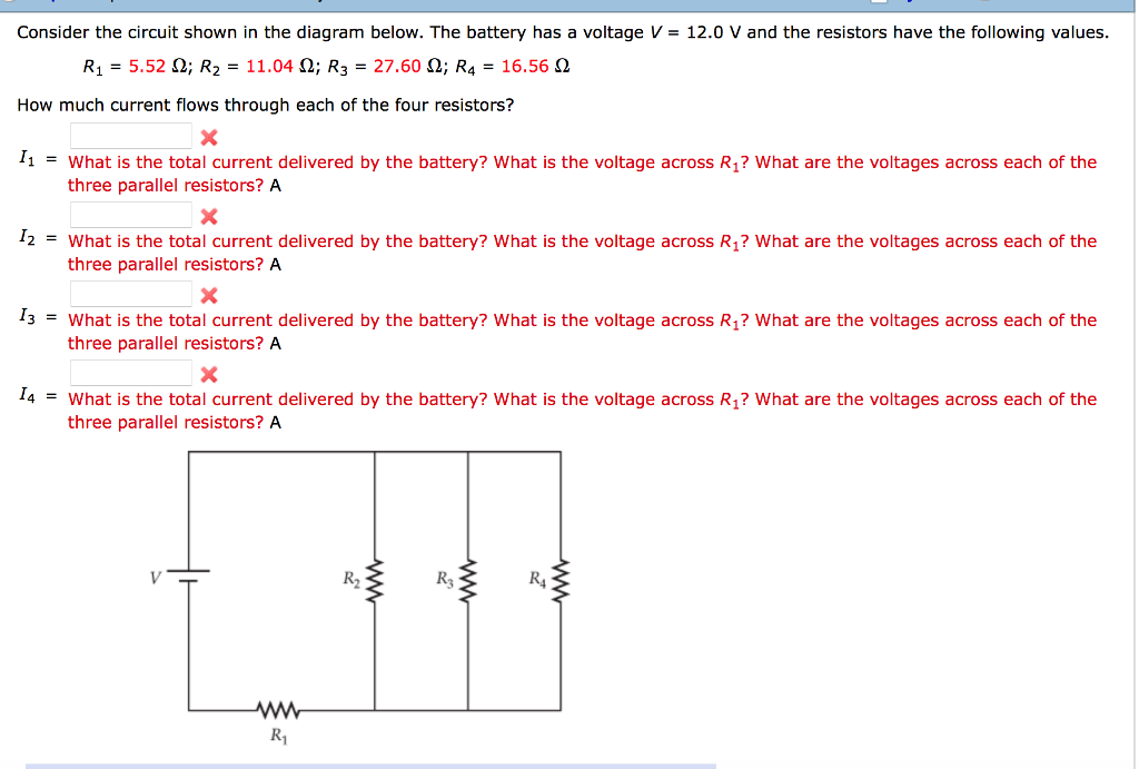
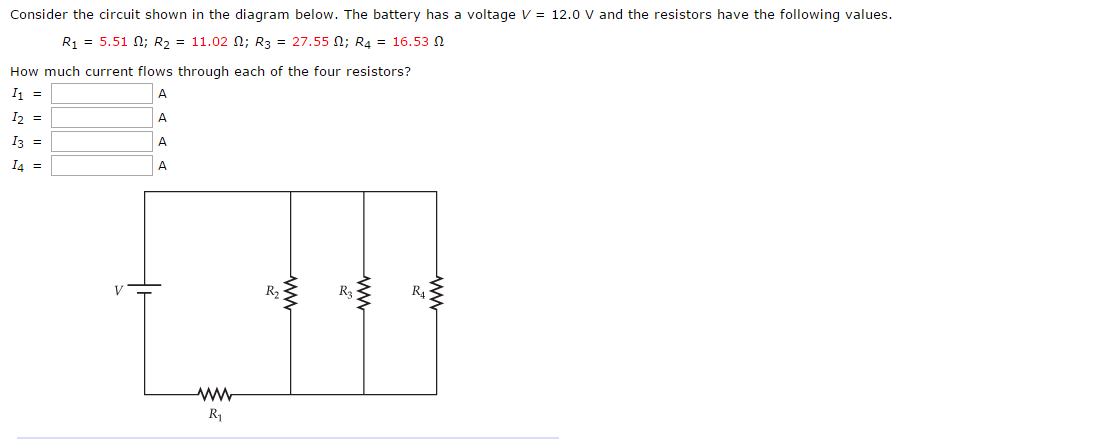
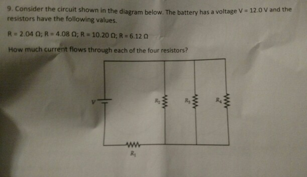
The diagram below shows the circuit for a small convector heater. Heater elements can be switched in and out of the circuit using switches X and Y. Each element has a resistance R and the power supply has an emf V. (a) The table shows the possible combinations of open and closed switches. When a switch is closed, charge can flow through it. 17 Consider the circuit shown in the diagram below. The battery has a voltage V = 12.0 V and the resistors have the following values. R1 = 2.32 2; R2 = 4.64 2, R2 = 11.60 2; R = 6.96 2 How much current flows through each of the four resistors? w RA ; Question: Consider the circuit shown in the diagram below. The battery has a voltage V = 12.0 V ... R 1= 4 Ω R 2= 2 Ω In the circuit below, what is the voltage across R 1? 1) 12 V 2) zero 3) 6 V 4) 8 V 5) 4 V The voltage drop across R 1 has to be twice as big as the drop across R 2. This means that V 1 = 8 V and V 2 = 4 V. Or else you could find the current I = V/R = (12 V)/(6 Ω) = 2 A, then use Ohm's Law to get voltages. The ohm (symbol: Ω) is the SI derived unit of electrical resistance, named after German physicist Georg Ohm.Various empirically derived standard units for electrical resistance were developed in connection with early telegraphy practice, and the British Association for the Advancement of Science proposed a unit derived from existing units of mass, length and time, and of a convenient scale ...
PHY2054: Chapter 21 2 Voltage and Current in RLC Circuits ÎAC emf source: "driving frequency" f ÎIf circuit contains only R + emf source, current is simple ÎIf L and/or C present, current is notin phase with emf ÎZ, φshown later sin()m iI t I mm Z ε =−=ωφ ε=εω m sin t ω=2πf sin current amplitude() m iI tI mm R R ε ε == =ω An electric potential diagram is a conceptual tool for representing the electric potential difference between several points on an electric circuit. Consider the circuit diagram below and its corresponding electric potential diagram. The circuit shown in the diagram above is powered by a 12-volt energy source. The total resistance of the circuit is R=Rbt+Rbulb=3.5 Ω + 19 Ω R=22.5 Ω The current through the 19-Ω resistor is I=VR=6 V22.5 Ω I=0.2667 A The voltage difference ΔVbulb across the 19-Ω resistor is calculated as follows: ΔV=5.0667 V Sample Circuit We consider the wires to have no resistance ... the current in the 20.0-Ω resistor and (b) the potential difference between points a and b. Kirchhoff's Rules ... Draw the circuit diagram and assign labels and symbols to all known and unknown quantities. Assign directions to the currents.
Phasor notation (also known as angle notation) is a mathematical notation used in electronics engineering and electrical engineering. can represent either the vector (, ) or the complex number + =, with =, both of which have magnitudes of 1. A vector whose polar coordinates are magnitude and angle is written .. The angle may be stated in degrees with an implied conversion from ...
q= (9.5 A)× (180s)=1710 C. Four 38-Ω resistors are connected in series to a 18-V battery of negligible internal resistance. Calculate the current flowing through each resistor. (You must provide an answer before moving to the next part.) The current flowing through each resistor is. Rseries= R1+ R2+ R3 +R4=4×38 Ω.
To verify that resistances in series do indeed add, let us consider the loss of electrical power, called a voltage drop, in each resistor in Figure 2.According to Ohm's law, the voltage drop, V, across a resistor when a current flows through it is calculated using the equation V = IR, where I equals the current in amps (A) and R is the resistance in ohms (Ω).
Chapter 4, Solution 7 We find the Thevenin equivalent across the 10-ohm resistor. To find VTh, consider the circuit below. 3Vx 5Ω 5Ω + + 4V 15Ω VTh - 6Ω
R L ω ω ω == + c R L ω= A Serial RL Circuit Result ECE 307-4 22 Frequency Response of a Circuit Example Define R and L values for a high pass filter with a cutoff frequency of 10KHz. Find |H(jω)|at 5 KHz Let We can't calculate R and L values independently. We can select R or L values then define the other RK=Ω1 c R L ω = 1000 15.9 2 ...
in the circuit diagram given below, AB is a uniform wire of resistance 1 5 Ω and length 1 m. It is connected to a cell E 1 of emf 2 V and negligible internal resistance and a resistance R The balance point with another cell E 2 of emf 7 5 mV is found at 3 0 cm from end A. Calculate the value of R.
2 = 3.0 Ω, and R 3 = 2.0 Ω, are connected in series to a 9.0 V battery. What is the power dissipated by R 2? Answer: 3.0 W Solution: The total current is in the series circuit is 1 A, so the power dissipated in R 2 is i2R 2=1 2!3=3W. 4. Three resistors, R 1 = 4.0 Ω, R 2 = 3.0 Ω, and R 3 = 2.0 Ω, are connected in parallel to a 9.0 V battery ...
![[Gerald R. Ford, half-length portrait, facing front, with arms crossed]. Photograph from the Presidential File Collection, 1974. Library of Congress Prints & Photographs Division. https://www.loc.gov/item/96522670/](https://images.unsplash.com/photo-1580130379902-56f3803c563f?ixlib=rb-1.2.1)
[Gerald R. Ford, half-length portrait, facing front, with arms crossed]. Photograph from the Presidential File Collection, 1974. Library of Congress Prints & Photographs Division. https://www.loc.gov/item/96522670/
The figure below shows how the transistor is set up when it is connected in a circuit as an amplifier. ... The capacitor C E connected across R E provides a short circuit path for the AC signal and reduce the effect of additional negative feedback due to the AC signal and a corresponding reduction in voltage gain. ... Given R C = 2 KΩ = 2000 ...
question with solution circuit diagramTweet you may want to read basic electrical Question 1: The value of current (I) flowing in the 1 Ω (ohm) resistor in the circuit shown in the figure below will be: We will solve this question using both KVL (kirchoff voltage law) and KCL (kirchoff current law): Applying KVL in…
Ques. An electric circuit consists of four resistors, R 1 = 12 Ohm, R 2 = 12 Ohm, R 3 = 3 Ohm and R 4 = 6 Ohm, are connected with the source of emf E 1 = 6 Volt, E 2 = 12 Volt. Determine the electric current flows in the circuit as shown in figure below. Known : Resistor 1 (R 1) = 12 Ω. Resistor 2 (R 2) = 12 Ω. Resistor 3 (R 3) = 3 Ω ...
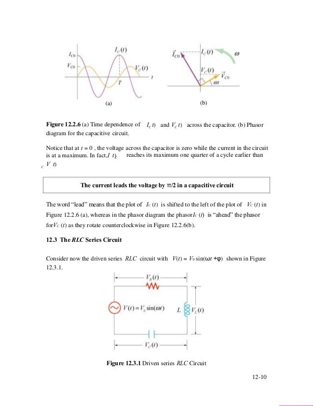
diagram for the resistive circuit. The behavior of IR (t)and can also be represented with a phasor diagram, as shown in Figure 12.2.2(b). A phasor is a rotating vector having the following properties: VR (t) (i) length: the length corresponds to the amplitude. (ii) angular speed: the vector rotates counterclockwise with an angular speed ω.
Consider the circuit shown in Figure P21.29. Find(a)the current in the R 1 = 20 resistor and(b)the potential di erence between points aand b. R 3 10.0 V 25.0 V R 4 10.0 R 5 5.00 5.00 R 2 1 20.0 a b Label the voltage V = 25:0 V and the resistances (clockwise from b) R 1 = 20:0, R 2 = 5:00, R 3 = 10:0, R 4 = 10:0, and R 5 = 5:00. Computing some ...
Example IV-1. Consider the circuit shown below, where R1 = 3.00 Ω, R2 = 10.0 Ω, R3 = 5.00 Ω, R4 = 4.00 Ω, and R5 = 3.00 Ω. (a) Find the equivalent resistance of this circuit. (b) If the total power supplied to the circuit is 4.00 W, find the emf of the battery. + − E R1 R2 R3 R4 R5 Solution (a): We have to reduce this circuit in steps ...
In the figure above, let R 1 = 4 Ω, R 2 = 4 Ω, and R 3 = 12 Ω. Then the equivalent resistance is R = 20 Ω. If the battery voltage is 10 V, then the current in the circuit is I = V/R = (10 V)/(20 Ω) = 0.5 A. The current through each resistor is 0.5 A. The power dissipated is P = IV = 5 W. Assume another 20 Ω resistor is added to the chain.
Apr 07, 2018 · A series RL circuit with R = 50 Ω and L = 10 H has a constant voltage V = 100 V applied at t = 0 by the closing of a switch. Find (a) the equation for i (you may use the formula rather than DE), (b) the current at t = 0.5 s (c) the expressions for V R and V L (d) the time at which V R = V L. Answer
Ω. A battery of emf 6 volt is connected across 0.30 m of resistance wire of diameter 1.0 mm. A current of 0.5 ampere flows through the wire. Question 13 (1984 Question 59) What current will flow if this wire is replaced by 1.20 m of the same wire? A circuit consists of a 12 volt battery and two 4 ohm resistors connected in series. Draw the ...
Example 5: RLC Circuit Consider the circuit shown below, assuming that R, L, V0 and ω are known. If both switches are closed initially, find the following: (a) the current as a function of time, (b) the average power delivered to the circuit, (c) the current as a function of time after only switch 1 is opened.
Q2.€€€€€€€€€ A cell of emf, ε, and internal resistance, r, is connected to a variable resistor R. The current through the cell and the terminal pd of the cell are measured as R is decreased. The circuit is shown in the figure below. Page 3 of 18
This circuit produces an output that is proportional to the input, that is v b = k v a where k is the constant of proportionality. (a) Determine the value of the output, v b, when R = 240 Ω and v a = 18 V. (b) Determine the value of the power supplied by the voltage source when R = 240 Ω and v a = 18 V.
Consider the electric circuit in the figure below with the following parameters: ε 1 = 24.00 V, ε 2 = 12.00 V, R 1 = 900 Ω, R 3 = 400 Ω.. 1.)What is the potential at point A? 2.)Calculate the current i 1.. 3.)Calculate the current i 3
in the diagram shown. Original circuit KLR on the loop containing battery and 3 resistor 1 13) Calculate the resistance of the unknown resistor, R in the diagram shown. Resistors in parallel OR KJR A KLR on outer loop 14. A 110-V household circuit that contains an 1800-W microwave, a 1000-W toaster, and an 800-W
The radio has a. 3.20 Ω. 3.20 Ω resistance. (a) Draw a circuit diagram of the radio and its battery. Now, calculate the power delivered to the radio (b) when using a nicad cells, each having an internal resistance of. 0.0400 Ω. 0.0400 Ω, and (c) when using an alkaline cell, having an internal resistance of. 0.200 Ω.
Pharmacological Basis For Nursing Interventions II (NUR 3192) Computer Information Systems (CIS 401) Human Anatomy (ANP 300) Introduction to Organic and Biological Chemistry (CHEM120-62398)
m m 6000 6000 3 16 16 3 v R R v + = ⇒= − (a) The voltage measured by the meter will be 4 volts when R = 6 kΩ. (b) The voltage measured by the meter will be 2 volts when R = 1.2 kΩ. P 4.3-9 Determine the values of the node voltages of the circuit shown in Figure P 4.3-9.. Figure P 4.3-9 . Solution: Express the voltage source voltages as functions of the node voltages to get
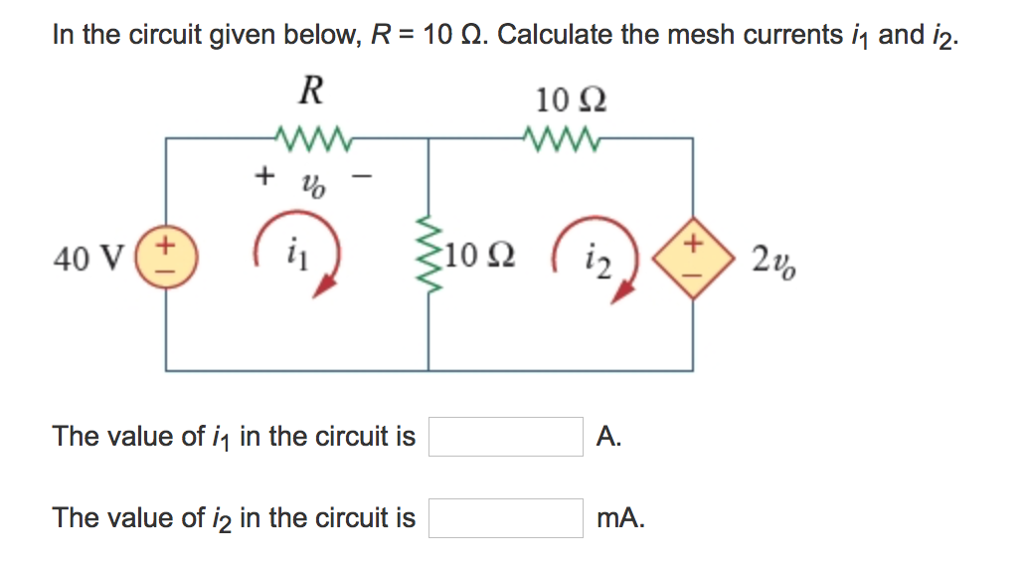

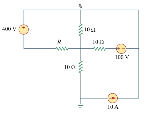











0 Response to "36 consider the circuit in the diagram below, in which r = 13 ω."
Post a Comment