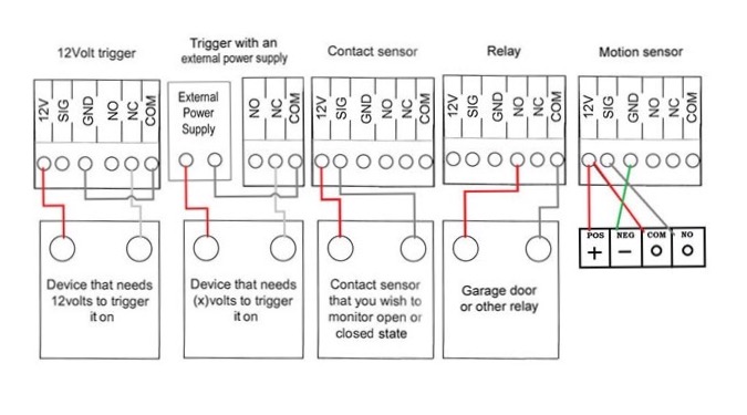
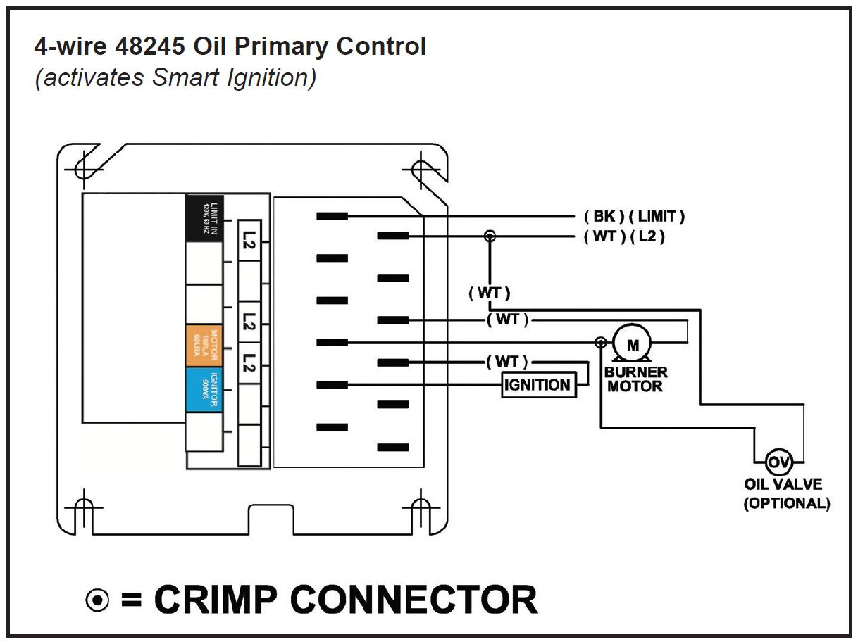
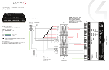
44 control 4 wiring diagram
accessconnect.com › trailer_wiring_diagramTrailer Wiring Diagram For 4 Way, 5 Way, 6 Way and 7 Way circuits 3/4 inch by 1 inch 6 way rectangle connectors right turn signal (green), left turn signal (yellow), taillight (brown), ground (white). The red and blue wire can be used for brake control or auxiliary. Use on a small motorcycle trailer, snowmobile trailer or utility trailer. Can also be used as custom wiring on trailers with 3 light/wire systems. PDF Basic Wiring for Motor Contol - Eaton control circuit may not be at the same voltage as the power circuit. When the voltage of the control and power circuits is the same, it is referred to as Common Control. If the volt-ages are different, it is called Separate Control. Figure 4. Typical Starter Wiring Diagram — Three-Phase Separate voltages supplied by different voltage sources.
forums.iboats.com › threads › yamaha-703-remoteYamaha 703 remote control wiring diagram | Boating Forum ... Sep 08, 2005 · Re: Yamaha 703 remote control wiring diagram usually 4 wires from that box. yellow is ignition supply to guages, green is tach signal, red is constant 12v for digital speedo memory (wont turn on without it), black is ground. some boxs have no red wire.
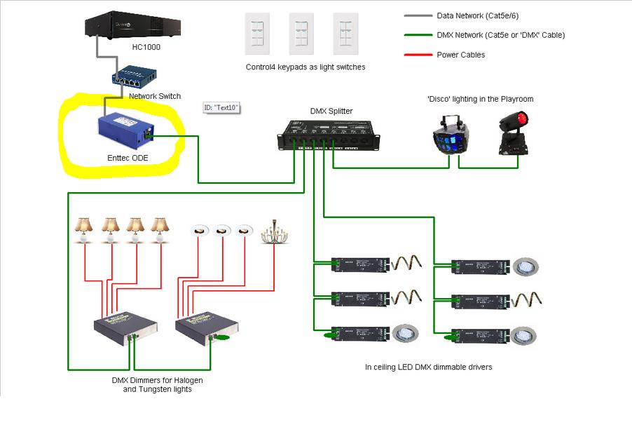
Control 4 wiring diagram
guitarelectronics.com › strat-style-guitar-wiringStrat Style Guitar Wiring Diagram - GuitarElectronics.com Jul 24, 2021 · Strat style guitar wiring diagram with three single coils, 5-way lever switch, 1 volume, 2 tones. Typical standard Fender Stratocaster guitar wiring with master volume plus 1 neck tone control and one middle pickup tone control. Please Note: This guitar wiring diagram is property of GuitarElectronics.com Inc. Everything You Need to Know About Wiring Diagram - SmartDraw Customize hundreds of electrical symbols and quickly drop them into your wiring diagram. Special control handles around each symbol allow you to quickly resize or rotate them as necessary. To draw a wire, simply click on the Draw Lines option on the left hand side of the drawing area. If you right click on a line, you can change the line's ... › forms › ToyEWBTOYOTA ELECTRICAL WIRING DIAGRAM - Autoshop 101 1. Describe the meaning of the "C13" in the diagram component Q. 2. Describe the meaning of the "G-W" in diagram component R. 3. Describe the meaning of the "2" in diagram component S. 4. Describe the meaning of the "S/D" in diagram component T. 5. Describe and identify the diagram component U. 6. Describe and identify the diagram component V. 7.
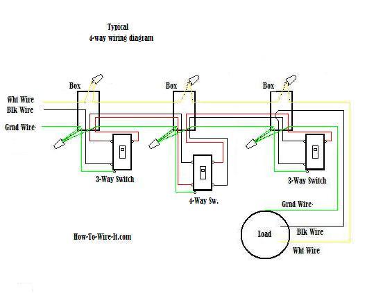
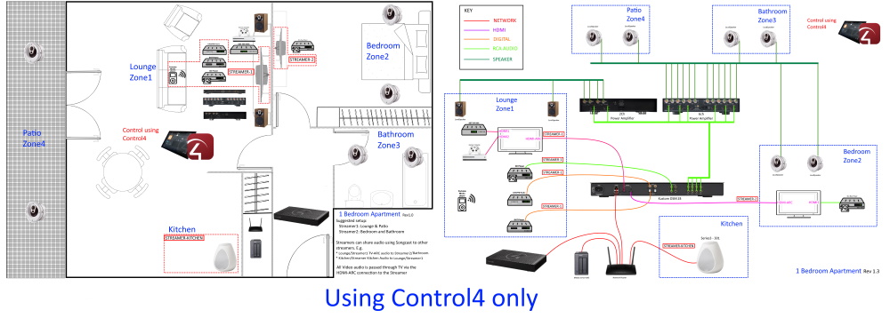
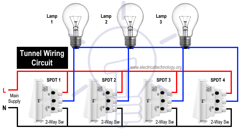
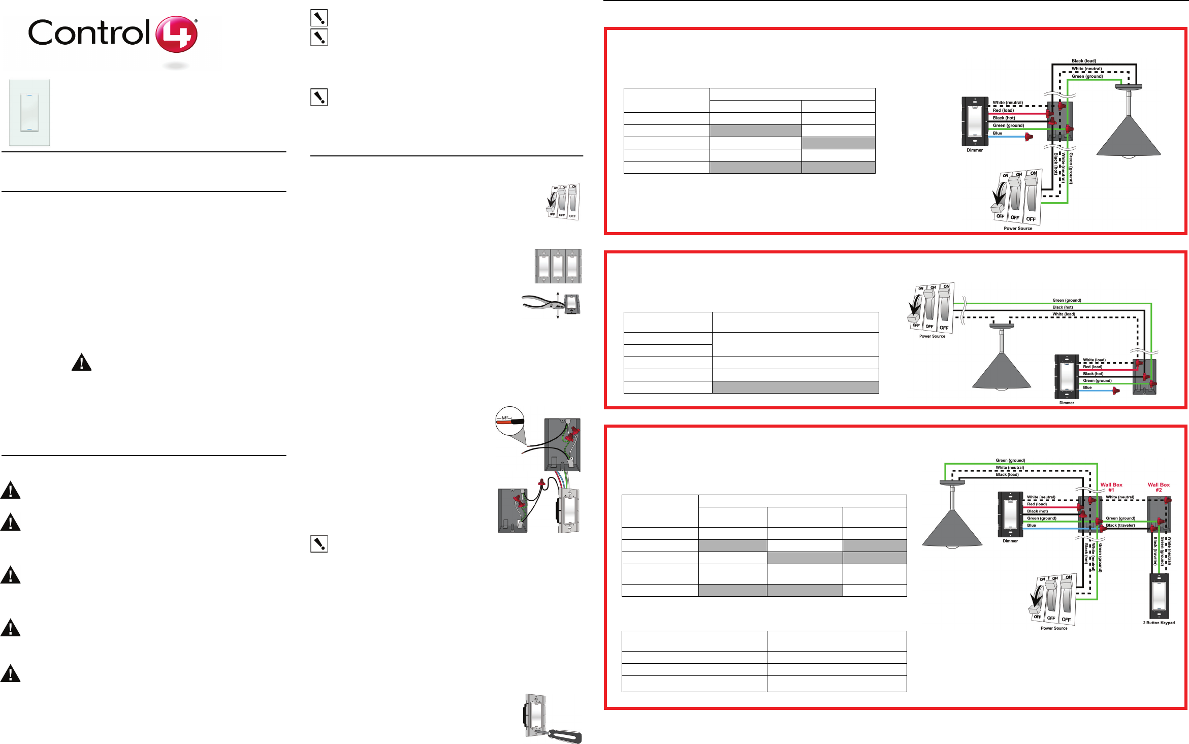
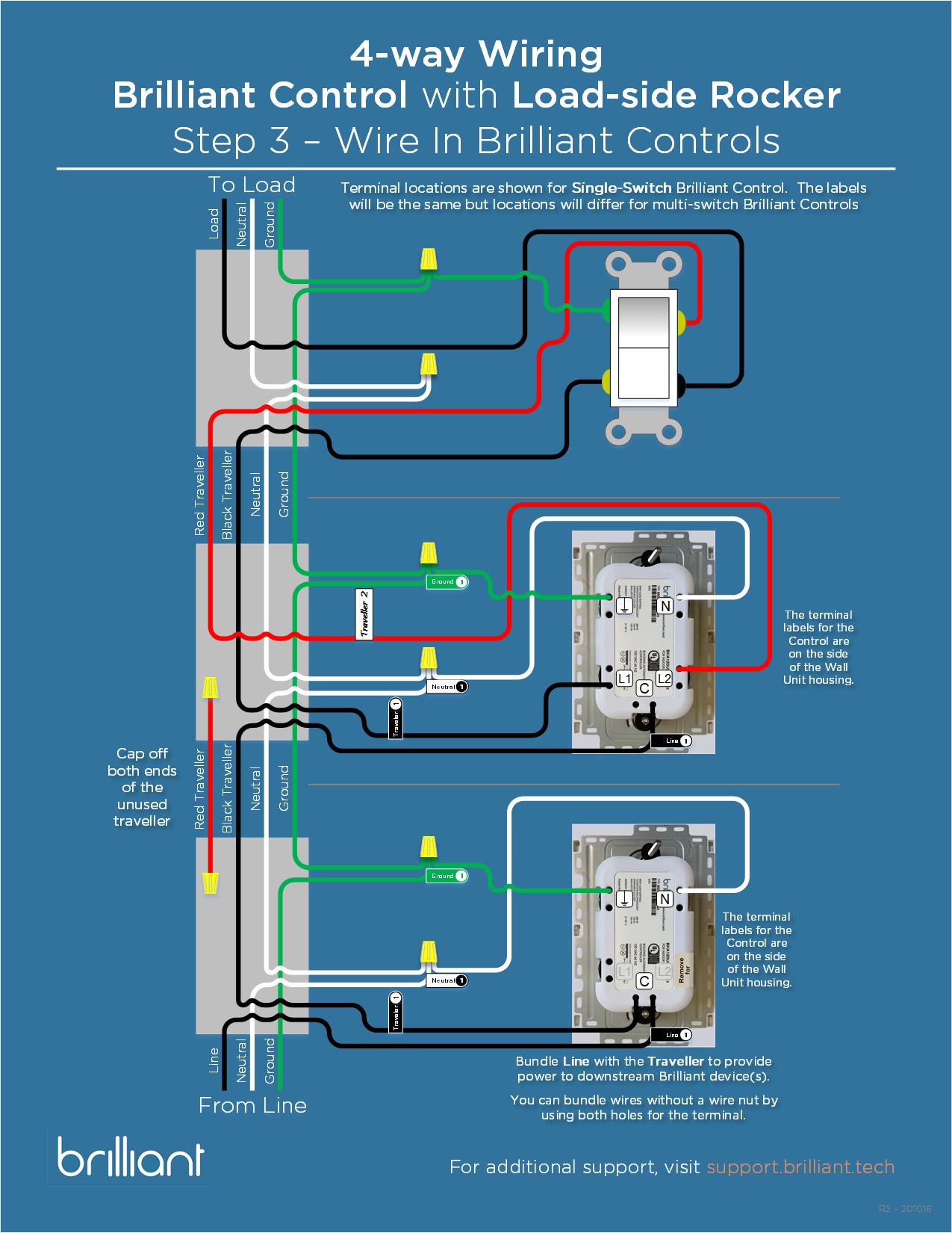
Control 4 wiring diagram. Standard Control4 Wiring Diagrams - Driver Discussion - C4 Forums Standard Control4 Wiring Diagrams Standard Control4 Wiring Diagrams. By andy.cytexone, January 6, 2006 in Driver ... the designing phase of a new home and was thinking about incorporating C4 in my house while the house is all studs and wiring is being pulled. Link to comment Share on other sites. More sharing options... Gene. Posted ... PDF Essential Lighting Wiring Guide - Control4 This diagram shows a sample 4-way wiring configuration using an Essential Forward Phase Dimmer (C4-V-FPD120) or Switch (C4-V-SW120-277) with two Essential Auxiliary Keypads (C4-V-AUX). Daisy-chain each additional Auxiliary Keypad by extending the Ground, Traveler, and Neutral to each keypad. › attachments › wiring5. Wiring Diagram - Subaru Forester Owners Forum Wiring Diagram A: POWER SUPPLY ROUTING SU01-04A 12 6-3 [D5A0] WIRING DIAGRAM 5. Wiring Diagram. SU01-04B 13 ... CRUISE CONTROL SYSTEM SU71-06 31 WIRING DIAGRAM [D5L0 ... Generac 22kw Control Wiring Diagram | champion Generac 22kw Wiring Schematic. Generac Transfer Switch Control Wiring Diagram. Generac Ats Wiring Diagram. Generac Gp17500e Wiring Diagram. Generac Gp7500e Wiring Diagram. Generac Gts Transfer Switch Wiring Diagram. Generac Transfer Switch Wiring Diagram. Generac 400 Amp Transfer Switch Wiring Diagram. Control 4 Wiring Diagramcontrol 4 Wiring ...
PDF Configurable Wired Keypad Installation Guide - Control4 Wiring diagrams For bus wiring details, refer to the Keypad Bus Wiring Guide (ctrl4.co/buswiring). Operation and configuration On initial power up, all status LEDs on the keypad will illuminate green, indicating that the device has power. Until the keypad has been configured into a Control4 system, it will not control any loads. › automotive-relay-diagramAutomotive Relay Diagram! 4 & 5 Pin Relay Wiring Diagram The automotive relay wiring diagram is not complicated, it’s very easy. All you need to know is the basics of a car relay wiring diagram. Here in this section, I am explaining the wiring diagram of the four and five-pin car relay. Stick with me, here I am giving you a little background about automotive relay terminals. ️Control 4 Wiring Diagram Free Download| Gmbar.co Control 4 wiring diagram. 1 termi nal on the remote pilot device and. Connect separate control lines to the no. The msr304 is an allen bradley safety relay. Wiring direct to battery not recommended. Wiring diagrams, sometimes called " main " or " construction " diagrams, show the actual connection points for the wires to the components ... Honeywell 4 Wire Zone Valve Wiring Diagram - Plumbingpoints Honeywell 4 wire zone valves need three 18/2 cables for correct wiring. The two yellow wires of the zone valve must be connected using a set of 18/2 cables. When it comes time to wire the zone valve, we will utilize a third 18/2 cable for the red wires. It is recommended that one of the yellow wires be connected to the thermostat.
Wired Keypads - Control4 Mix-and-match engraved buttons and sleek, screwless faceplates with nine stylish colors and gloss and satin finishes. Buttons allow for quick control of your favorite scenes. For example, a "Goodnight" button can be configured to shut off all the lights, lock the doors and arm the alarm, all at once. Check Lighting Compatibility. See All Products. Control 4 Wiring Diagramcontrol 4 Wiring Diagram - champion 21 posts related to Control 4 Wiring Diagramcontrol 4 Wiring Diagram. Electrical Wiring Yamaha 703 Remote Control Wiring Diagram. Vintage Air Control Wiring Diagram. Gecko Spa Control Wiring Diagram. Mercury 8 Pin Control Box Wiring Diagram. Ge 300 Line Control Wiring Diagram. › wiring-diagramWiring Diagram – A Comprehensive Guide | EdrawMax Online Step 4: Make your wiring diagram. from different tools. In this window, you can create your wiring diagram by choosing different wiring diagram symbols from the symbol library. There are various symbols available such as transmission path, qualifying symbols, semiconductor devices, switches and relays, and other necessary electrical symbols. PDF Switch Installation Guide - Control4 3 Prepare each wire. Wire insulation should be stripped back 5/8 of an inch from the wire end (see Figure 1). Figure 1. Strip wire insulation 4 Identify your wiring application, and then see the appropriate wiring diagram in the "Sample Wiring Configurations" section below. IMPORTANT! Not grounding this product, as described in the section
Control 4 Wiring Diagram Collection - got2bwireless.com Control 4 Wiring Diagram from i1.wp.com Print the cabling diagram off plus use highlighters to be able to trace the routine. When you employ your finger or perhaps the actual circuit along with your eyes, it is easy to mistrace the circuit.
4 Wire Dump Trailer Remote Control Switch Wiring Diagram The Dump Trailer Remote Control Switch is a great upgrade over the original 4-wire double-acting hydraulic power unit. It features a 2-button pendant control, a mounting holster, and is a perfect replacement for lift gate or elevator lifter. With its low weight and space-saving design, it won't take up a lot of space.
encoder wiring diagram Diagram transfer case 1999 wiring chevy control k3500 4x4 truck silverado 3500 actuator 2005 4wd repair schematics justanswer manual need. Transformer 480v 120v 240v ngbf. 1756 of8 plc 1769 thaicontrol ... [KD_5494] Plc Wiring Diagrams Also Allen Bradley 1756 On Plc Card wida.nekout.lectu.isop.vira.mohammedshrine.org. 1756 of8 plc 1769 thaicontrol.
Stashes - Control4 Essential Forward Phase Dimmer, 120V (White) Installation Guide. Essential Lighting Professional Wiring Guide. Essential Lighting Comparison. Essential Switch, 120V/277V (White) Data Sheet. Essential Switch, 120V/277V (White) Installation Guide. Plug-In Outlet Dimmer Data Sheet.
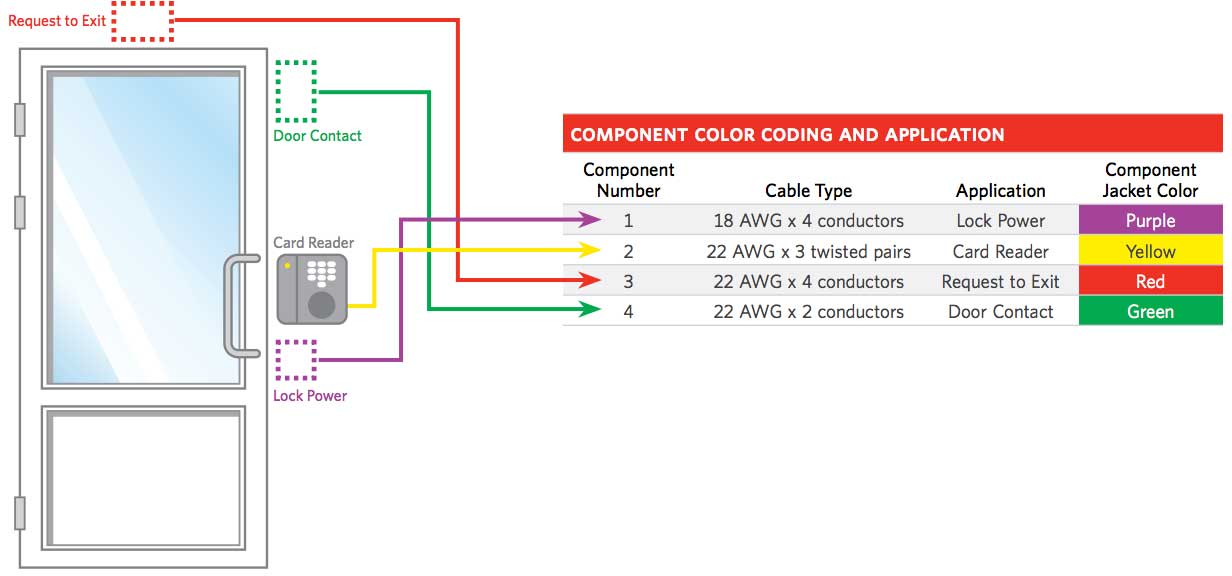
️Control 4 Wiring Diagram Free Download| Gambr.co Control 4 wiring diagram (GAMBR.CO) - This post is called control 4 wiring diagram. Wiring diagrams show the connections to the controller. Security door controls ¡ 4 1. It shows the components of the circuit as streamlined shapes, and the power as well as signal links between the gadgets. 4.3 tbi wiring diagram 22.10.2018 ...
4 Wire Ignition Switch Diagram: (How It Works!) » Scooter Tip Installing a 4-wire ignition switch in your vehicle is a simple process that can save you time and hassle. Follow these steps to get the job done: 1. Disconnect the negative battery cable. 2. Remove the screws that hold the cover on the ignition switch housing and remove housing.
PDF Switch Installation Guide - Control4 Control Communications ZigBee, IEEE 802.15.4, 2.4 GHz, 15-channel spread spectrum radio Wallbox Volume 5.75 cubic inches Weight 0.12 lb (0.05 kg) Shipping Weight 0.18 lb (0.08 kg) ... 4 Identify your wiring application, and then see the appropriate wiring diagram in the "Sample Wiring Configurations" section below. IMPORTANT! Not grounding ...
Read Free Star Delta Starter Control Wiring Diagram Answer 4 4 Star Delta Starter Control Wiring Diagram Answer 17-09-2022 of Bus bar for Panel 307 19 Calculate Size of Cable Tray 312 20 Calculate Size of Diesel Generator Set 314 21 Calculate Size of Main ELCB & Branch MCB of Distribution Box 317 22 Calculate Size of Solar Panels 322 23 Calcu-
Control 4 Switch Wiring Diagram - Wiring Diagram And Schematics ... Feb 23, 2019 - Control 4 Switch Wiring Diagram - Wiring Diagram And Schematics. Feb 23, 2019 - Control 4 Switch Wiring Diagram - Wiring Diagram And Schematics. Pinterest. Today. Explore. When autocomplete results are available use up and down arrows to review and enter to select. Touch device users, explore by touch or with swipe gestures.
️Control 4 Wiring Diagram Free Download| Goodimg.co Control 4 wiring diagram (GOODIMG.CO) - Phase 2 l1, l2, l3 ground, when used A wiring diagram normally gives info about. This is the wiring for a dimmer in a 4 way circuit. A wiring diagram is a simple visual representation of the physical connections and physical layout of an electrical system or circuit. Use copper wire (75ºc min) only ...
PDF Control4® Panelized Lighting: Reference Guide for Electricians Figure 1). Panelized lighting utilizes a centralized/star wiring configuration, where circuits from the breaker box are routed first to a centrally-located enclosure (panel), which houses dimmer, relay, and other system control modules. From there, the switched/dimmed circuits are routed directly to the loads (see Figure 2).
› forms › ToyEWBTOYOTA ELECTRICAL WIRING DIAGRAM - Autoshop 101 1. Describe the meaning of the "C13" in the diagram component Q. 2. Describe the meaning of the "G-W" in diagram component R. 3. Describe the meaning of the "2" in diagram component S. 4. Describe the meaning of the "S/D" in diagram component T. 5. Describe and identify the diagram component U. 6. Describe and identify the diagram component V. 7.
Everything You Need to Know About Wiring Diagram - SmartDraw Customize hundreds of electrical symbols and quickly drop them into your wiring diagram. Special control handles around each symbol allow you to quickly resize or rotate them as necessary. To draw a wire, simply click on the Draw Lines option on the left hand side of the drawing area. If you right click on a line, you can change the line's ...
guitarelectronics.com › strat-style-guitar-wiringStrat Style Guitar Wiring Diagram - GuitarElectronics.com Jul 24, 2021 · Strat style guitar wiring diagram with three single coils, 5-way lever switch, 1 volume, 2 tones. Typical standard Fender Stratocaster guitar wiring with master volume plus 1 neck tone control and one middle pickup tone control. Please Note: This guitar wiring diagram is property of GuitarElectronics.com Inc.











0 Response to "44 control 4 wiring diagram"
Post a Comment