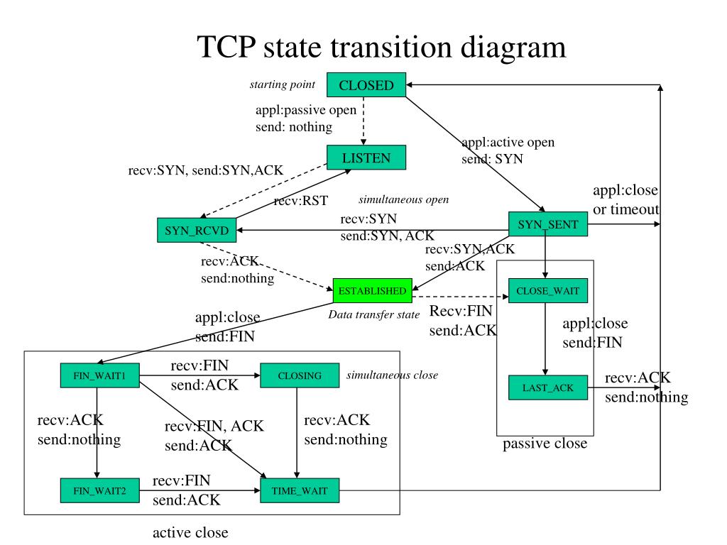
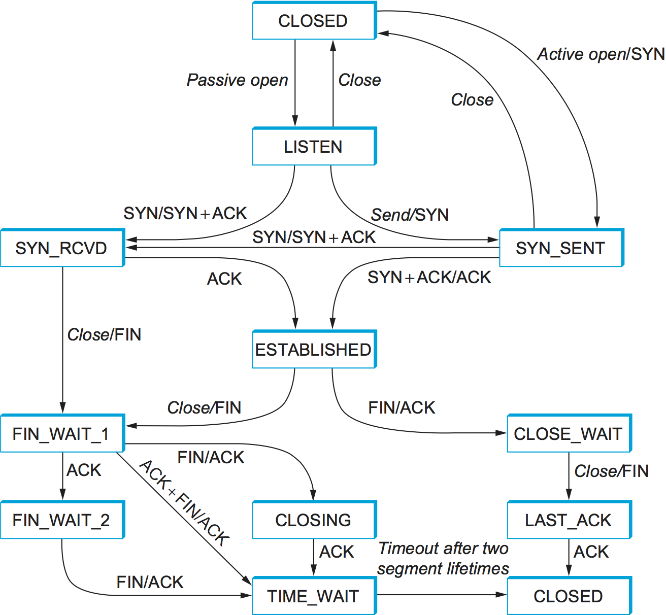
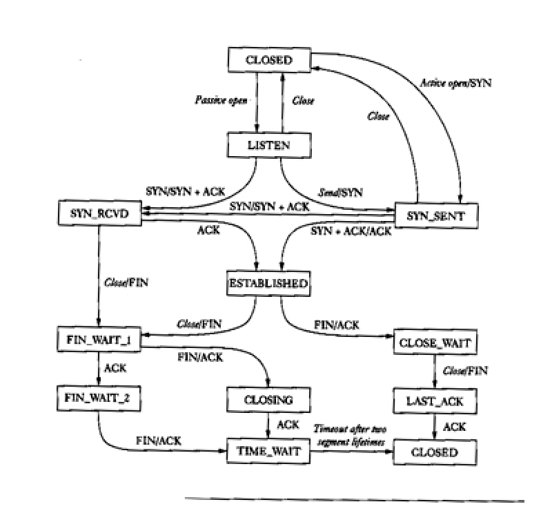
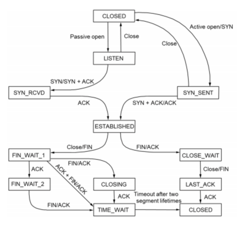
43 tcp state transition diagram
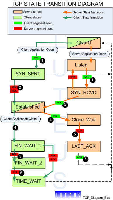
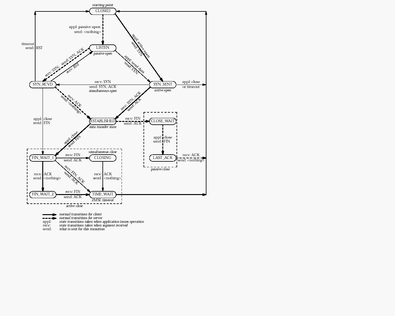
TCP connection status - IBM TCP connection status A TCP connection progresses through a series of states during its lifetime. The following diagram illustrates the possible states for a TCP connection and how the states transition based on various events from either the network or from the local TCP sockets application. Figure 1. TCP state transition diagram Clients or Users Establishment of a TCP connection, state diagram - LoriotPro Principle termination of a TCP connection state diagram The termination of a TCP connection requires four exchanges of TCP segments. As a TCP connection is bidirectional (full duplex) , connection termination process should be made in both directions of the communication.
Transmission Control Protocol - tutorialspoint.com TCP communication between two remote hosts is done by means of port numbers (TSAPs). Ports numbers can range from 0 - 65535 which are divided as: System Ports (0 - 1023) User Ports ( 1024 - 49151) Private/Dynamic Ports (49152 - 65535) Connection Management TCP communication works in Server/Client model.
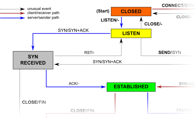
Tcp state transition diagram
File:Tcp state diagram fixed new.svg - Wikimedia Commons This is a retouched picture, which means that it has been digitally altered from its original version.Modifications: Modified version of TCP state diagram, with receipt of ACK added as requirement for CLOSING->TIME_WAIT and LAST_ACK->CLOSED transitions.The original can be viewed here: Tcp state diagram fixed.svg: .Modifications made by Scil100. Explain the transition states of TCP with a neat diagram - Ques10 To keep track of all the different events happening during connection establishment, connection termination, and data transfer, TCP is specified as the finite state machine shown in Figure. The figure shows the two FSMs used by the TCP client and server combined in one diagram. The ovals represent the states. TCP transition-state-diagram. | Download Scientific Diagram - ResearchGate TCP transition-state-diagram. Source publication Towards Bottleneck Identification in Cellular Networks via Passive TCP Monitoring Conference Paper Full-text available Jun 2014 Mirko Schiavone...
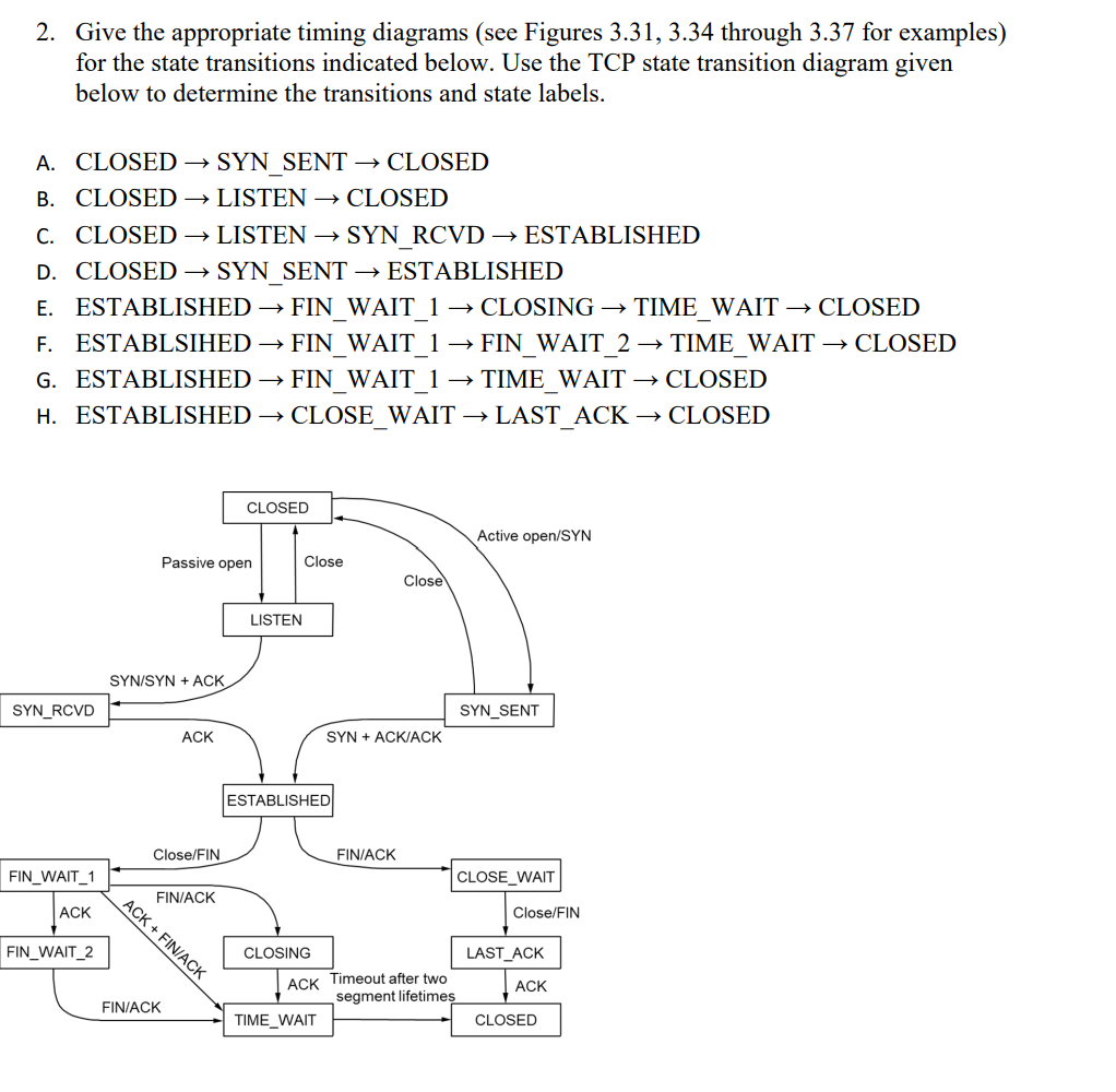
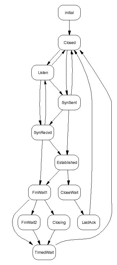
Tcp state transition diagram. Chapter 2. The Transport Layer: TCP, UDP, and SCTP - Shichao TCP State Transition Diagram ¶ There are 11 different states defined for a connection and the rules of TCP dictate the transitions from one state to another, based on the current state and the segment received in that state. Watching the Packets ¶ In the TCP state transition diagram, why do we have the TIME ... - Ques10 If the last ACK segment is lost, the server TCP, which sets a timer for the last FIN (Finish) bit set, assumes that its FIN is lost and resends it. If the client goes to the CLOSED state and closes the connection before the 2MSL timer expires, it never receives this resent FIN segment, and consequently, the server never receives the final ACK. Project 4: A TCP State Transition Program - cs.uni.edu The Transmission Control Protocol (TCP) is a protocol used on top of IP to help guarantee a reliable stream of data from the sender to the receiver. The purpose of this assignment is to get you familiar with how TCP works. A State Transition Diagram The figure below shows a state transition diagram for TCP. TCP State Transition Diagram - FAU TCP State Transition Diagram zurück. zurück
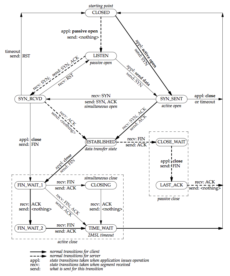
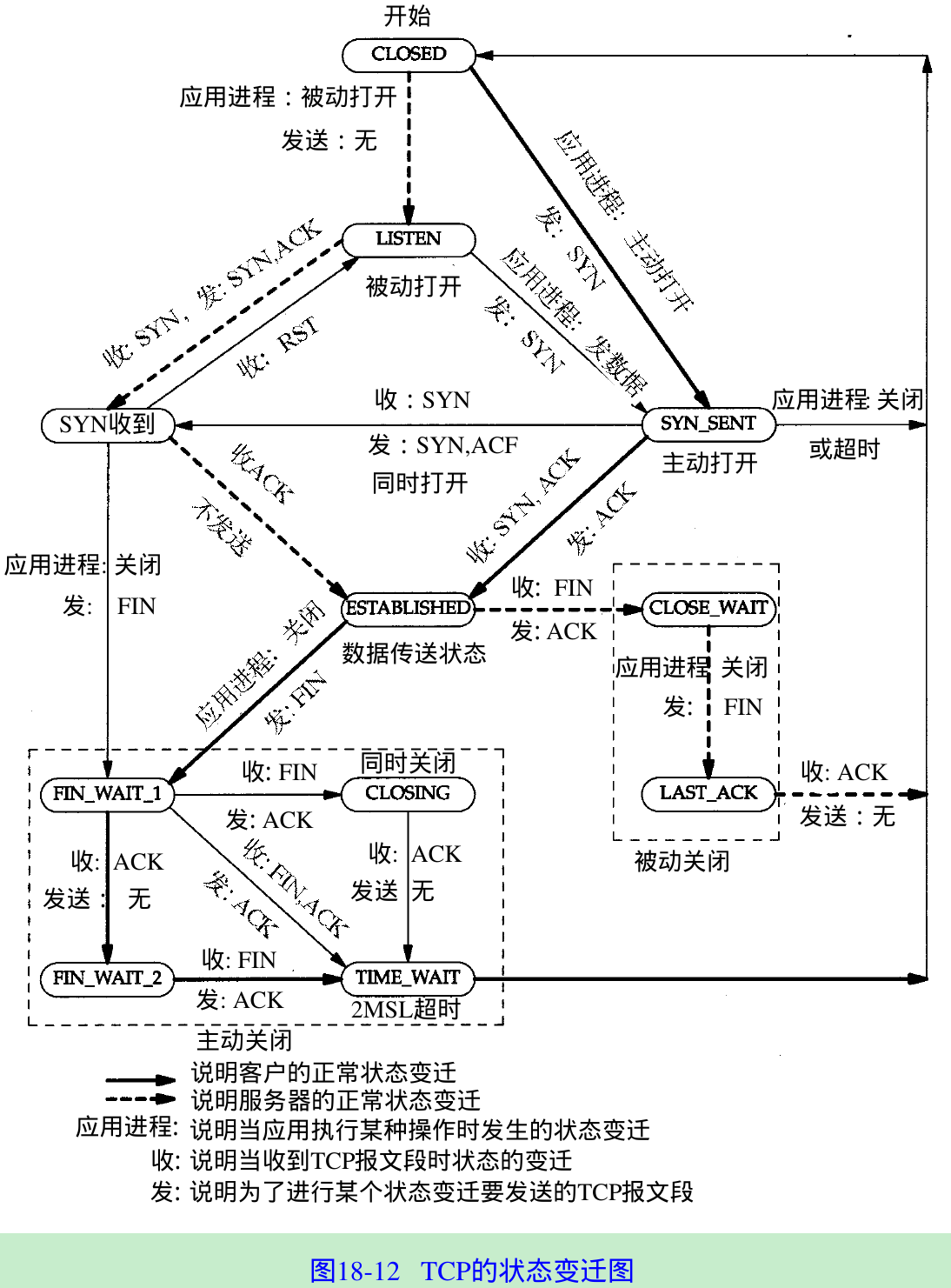
File:Tcp state diagram fixed.svg - Wikipedia File:Tcp state diagram fixed.svg. Size of this PNG preview of this SVG file: 796 × 600 pixels. Other resolutions: 319 × 240 pixels | 637 × 480 pixels | 1,019 × 768 pixels | 1,280 × 965 pixels | 2,560 × 1,929 pixels | 1,084 × 817 pixels. This is a file from the Wikimedia Commons. Information from its description page there is shown below. TCP Connection Termination - GeeksforGeeks In these two state-transition figures, we have only shown how a TCP connection is normally established and shut down. TCP states visited by ClientSide - TCP states visited by ServerSide - Here we have not described what happens in certain scenarios like when both sides of a connection want to initiate or shut down at the same time. TCP State Transition Diagram | The Daily Programmer TCP State Transition Diagram Simultaneous Open - when both ends send SYN simultaneously. Simultaneous Close - when both ends send FIN simultaneously. There are 11 different states defined for a connection and the rules of TCP dictate the transitions from one state to another, based on the current state and the segment it received. Chapter 18. TCP Connection Establishment and Termination 18.6 TCP State Transition Diagram. We've described numerous rules regarding the initiation and termination of a TCP connection. These rules can be summarized in a state transition diagram, which we show in Figure 18.12. The first thing to note in this diagram is that a subset of the state transitions is "typical." We've marked the normal client ...
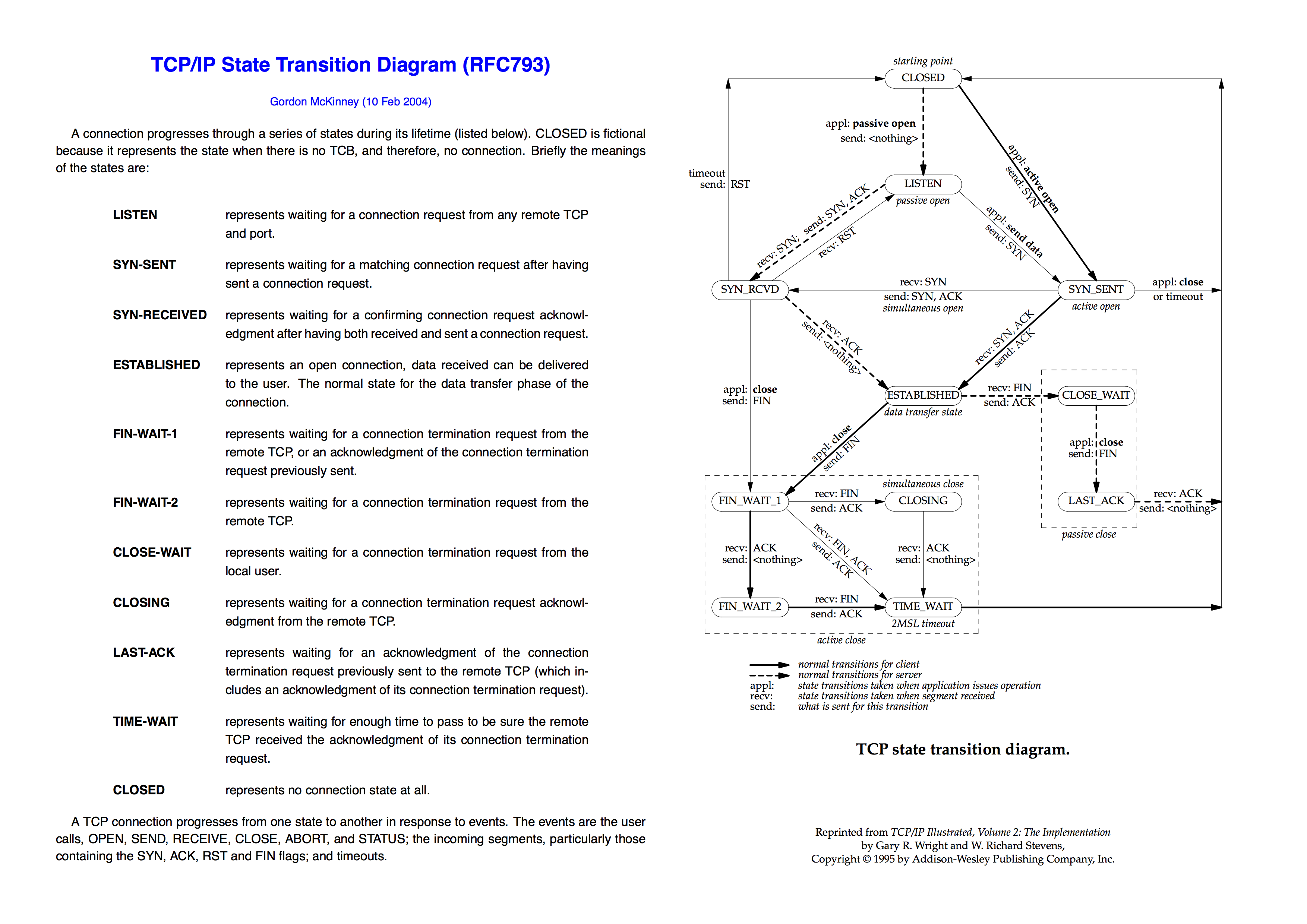
TCP state transition diagram - Code World TCP operations involving connection establishment and termination can be illustrated by the following state transition diagrams. TCP defines 11 states for a connection that can be displayed using netstat, and TCP rules specify how to transition from one state to another based on the current state and the segments received in that state. TCP 3-Way Handshake Process - GeeksforGeeks Step 1 (SYN): In the first step, the client wants to establish a connection with a server, so it sends a segment with SYN (Synchronize Sequence Number) which informs the server that the client is likely to start communication and with what sequence number it starts segments with. Step 2 (SYN + ACK): Server responds to the client request with ... PDF TCP state transition diagram. - University of Washington appl: state transitions taken when application issues operation recv: state transitions taken when segment received send: what is sent for this transition TCP state transition diagram. Reprinted from TCP/IP Illustrated, Volume 2: The Implementation by Gary R. Wright and W.RichardStevens, TCP state-transition diagram | Download Scientific Diagram - ResearchGate TCP state-transition diagram Source publication Efficient Reachability Analysis of Hierarchical Reactive Machines Conference Paper Full-text available Jul 2000 Rajeev Alur Radu Grosu Michael...
GATE CS Applied Course gatecse@appliedroots.com. Importance of the GATE exam. Register. Login. COURSES. GATE PYQs. GATE CS Blogs. GATE 2022 TEST SERIES. GATE 2023 TEST SERIES.
topic - solutions adda TCP-Transition-Diagram. Question 1. Consider a TCP client and a TCP server running on two different machines. After completing data transfer, the TCP client calls close to terminate the connection and a FIN segment is sent to the TCP server. Server-side TCP responds by sending an ACK, which is received by the client-side TCP.
TCP states - explained - Google Cloud Community The server should close after a period of time defined by the Maximum Segment Lifetime (MSL). TCP A TCP B 1. ESTABLISHED ESTABLISHED 2. (Close) FIN-WAIT-1 --> --> CLOSE-WAIT 3. FIN-WAIT-2 <-- <-- CLOSE-WAIT 4.
TCP state transition diagram | TCP transition diagram - YouTube This lecture is taught by Sachin Shah M.Tech. (CSE) IIT Guwahati, Co-founder of Success GATEway ( ) _____...
TCP State Transitions - SourceForge TCP is specially designed to deal with "Simultaneous Open", during which only one TCP connection is established, not two. The state transitions are shown in the following figure: During "Simultaneous Open", 4 packets are exchanged, 1 packet more than in normal situations. 2. Simultaneous Close.
TCP (Transmission Control Protocol) - State Transition Diagram TCP (Transmission Control Protocol) - State Transition DiagramEC 8551 - COMMUNICATION NETWORKS - UNIT - IV2017 - REGULATION - ANNA UNIVERSITY
TCP state transition diagram - Code World Now both A and B are in the ESTABLISHED state, A's application process sends a connection release segment to its TCP, and actively closes the TCP connection. A enters the FIN_WAIT1 (termination wait 1) state. Then B confirms, and B enters the CLOSE_WAIT (close wait) state. At this time, TCP is in a half-closed state, and A has no data to send.
What is State Transition Testing? Diagram, Technique, Example - Guru99 In Software Engineering, State Transition Testing Technique is helpful where you need to test different system transitions. Two main ways to represent or design state transition, State transition diagram, and State transition table. In state transition diagram the states are shown in boxed texts, and the transition is represented by arrows.
PDF TCP/IP State Transition Diagram (RFC793) - Northwestern University TCP/IP State Transition Diagram (RFC793) Gordon McKinney (23 Feb 2002) A connection progresses through a series of states during its lifetime. The states are: LISTEN, SYN-SENT, SYN-RECEIVED, ESTABLISHED, FIN-WAIT-1, FIN-WAIT-2, CLOSE-WAIT, CLOSING, LAST-ACK, TIME-WAIT, and the fictional state CLOSED.
18.6 TCP State Transition Diagram | TCP/IP Illustrated, Vol. 1: The ... You should follow through the state changes in Figure 18.13 using the state transition diagram in Figure 18.12, making certain you understand why each state change takes place. 2MSL Wait State The TIME_WAIT state is also called the 2MSL wait state. Every implementation must choose a value for the maximum segment lifetime (MSL).
Tcp State Transition Diagram - Digital Transmission A TCP connection goes through a series of states during its lifetime. Figure 8.28 shows the state transition diagram. Each state transition is indicated by an arrow, and the associated label indicates associated events and actions. Connection establishment begins in the CLOSED state and proceeds to the ESTABLISHED state.
TCP transition-state-diagram. | Download Scientific Diagram - ResearchGate TCP transition-state-diagram. Source publication Towards Bottleneck Identification in Cellular Networks via Passive TCP Monitoring Conference Paper Full-text available Jun 2014 Mirko Schiavone...
Explain the transition states of TCP with a neat diagram - Ques10 To keep track of all the different events happening during connection establishment, connection termination, and data transfer, TCP is specified as the finite state machine shown in Figure. The figure shows the two FSMs used by the TCP client and server combined in one diagram. The ovals represent the states.
File:Tcp state diagram fixed new.svg - Wikimedia Commons This is a retouched picture, which means that it has been digitally altered from its original version.Modifications: Modified version of TCP state diagram, with receipt of ACK added as requirement for CLOSING->TIME_WAIT and LAST_ACK->CLOSED transitions.The original can be viewed here: Tcp state diagram fixed.svg: .Modifications made by Scil100.










0 Response to "43 tcp state transition diagram"
Post a Comment