40 motor control circuit diagram pdf
Wiring diagrams for the various configurations are below. If you are unsure, please feel free to contact us. We are happy to explain further or talk about custom options if you don't see what you're looking for. Figure 1: Parts JCXX06P1X-XX - 3phase Starter with Start/Stop button, direct- online wiring diagram Aug 19, 2020 — Transferring From Schematic to Wiring Diagram for Connection Purposes. 69. 23. Motor-Lead Connections. 73. 24. Self Test 4.189 pages
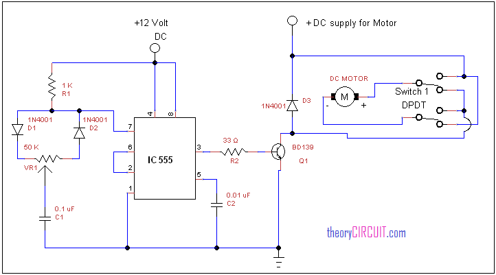
Basic DC Motor Circuits! Living with the Lab! Gerald Recktenwald! Portland State University! gerry@pdx.edu! LWTL: DC Motor! 2! DC Motor Learning Objectives! • Explain the role of a snubber diode! • Describe how PWM controls DC motor speed! • Implement a transistor circuit and Arduino program for PWM control of the DC motor!

Motor control circuit diagram pdf
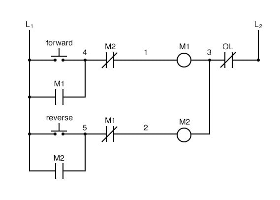
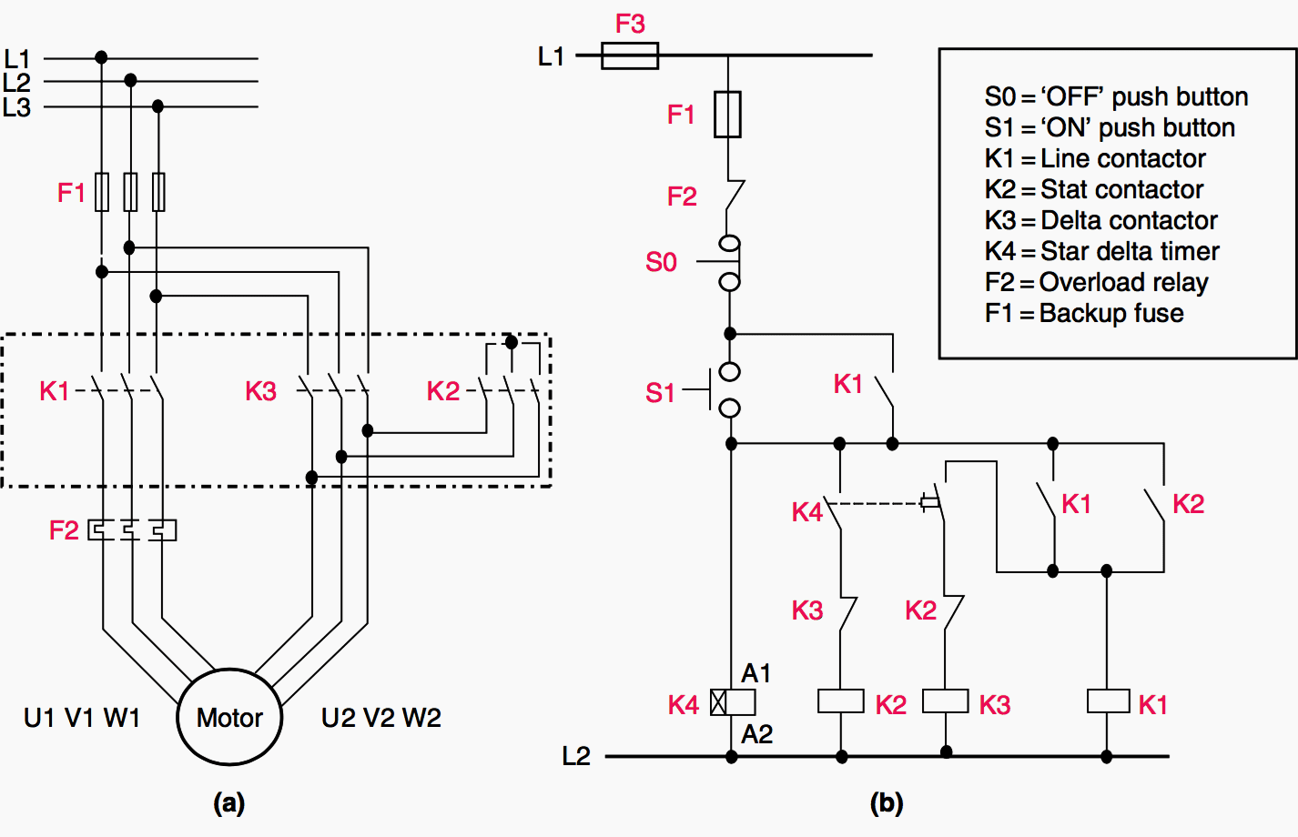
Three phase motor control circuit diagram pdf. The finished project contains electrical diagrams panel mechanical layout and various lists. Star delta y δ 3 phase motor starting method by automatic star delta starter with timer. Three phase motor connection star delta without timer power control diagrams. Phase 1 l2 l4. Maxim > Design Support > Technical Documents > Tutorials > Interface Circuits > APP 4697 Keywords: motor control, industrial control, hall effect sensor, DC Motor, brushless DC, AC induction, electrical components, block diagram, TUTORIAL 4697 Overview of Industrial Motor Control Systems By: Sohail Mirza, Application Manager May 10, 2010 The interlock contacts installed in the previous section's motor control circuit work fine, but the motor will run only as long as each push button switch is held down.. If we wanted to keep the motor running even after the operator takes his or her hand off the control switch(es), we could change the circuit in a couple of different ways: we could replace the push button switches with ...
Motor control circuit diagram pdf. The following are the circuit symbols commonly used in motor related schematic diagrams. Note: The following symbol was developed by Telemecanique and is still ...42 pages Download full-text PDF Read full-text. Download full-text PDF. ... circuit diagram help from this book. Give your feedback by mailing me. ... Dual Motor Control fo r Robots 133. 222. Optical ... Industrial Motor Control Circuits. Electrical motor circuits can be presented as: Block diagrams. Single line diagrams. Wiring diagrams. Schematic diagrams.12 pages Note: In this publication the line diagrams show the control circuits only - power circuits are omitted for clarity, since they can be traced readily on the wiring diagrams (heavy lines). A wiring diagram gives the necessary information for actually wiring-up a group of control devices or for
Wiring of the Direct-On-Line (DOL) Motor Starter 1) Three Phase Supply 230Volt Coil - see wiring diagram. (1) The following links are pre-fitted to the starter; 13 - 17 with a flying lead to be connected to Overload terminal 95; A2 - 14 - 18. All other control and power connections have to be made by the installer. Electrical Engineering World 88 Motor Control Wiring Diagrams Pdf Link Https Bit Ly 326tx0x Facebook. Basic wiring for motor control technical data guide eep 1 principles of controls circuits and applied electricity ladder logic electronics textbook types electrical automation plc programming scada pid system steppermotor controller with attiny13. 3 Phase Contactor Wiring Diagram Pdf Types Of Electrical Wiring, ... Wiring Diagram For Motor Starter 3 Phase Controller Failure Relay Electrical Pleasing ... Tutorial - Motor Control o Shows you how to make a small control circuit, where all components are found in the component database. The finished project contains electrical diagrams, panel mechanical layout and various lists. o The project looks like PCSMOTORDEMO1. In this way you can always check that you have been through all steps.
These diagrams are current at the time of publication, check the wiring diagram supplied with the motor. *NOTE: Refer to the motor manufacturer's data on the motor for wiring diagrams on standard frame Ex e, Ex d etc. motors. Inst Maint & Wiring_5.qxd 20/11/2015 11:37 AM Page 6 These diagrams are current at the time of publication, check the wiring diagram supplied with the motor. These diagrams apply to INTELLIGENT CONTROL MOTORSthat are fitted to the following products:-Pgs OCD/EEC.. Gamma EC D-50/51 Diags. IC1, 2 OCD/EEC..VGLGL Gamma EC D-52/53 Diags. IC1, 2 Control Circuit: This is the other motor starter circuit, which operates the contactor to turn it on or off. The contactor main contacts are responsible for allowing or interrupting the flow of current to the motor. To do this, the contacts in the control circuit are either opened or closed. The control circuit energizes In this application the MR204 is used to control a Point Motor, a Signal, and 2 LED's at the Control Panel. This circuit also has a CDU to help move the points, if required. The switch is a Momentary action Mini Toggle Switch, (this can be replaced by 2 mini Push Button switches).

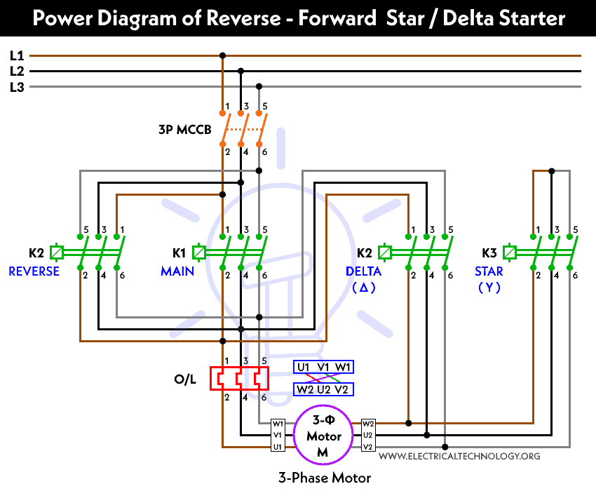
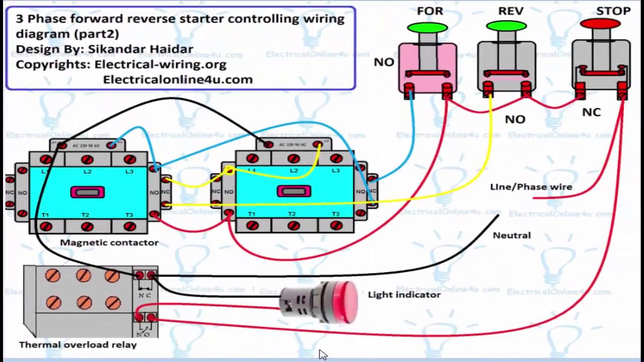
How To Wire Mgr Electrical Motor Controller Dpdt Reversing Switch Wiring Huimultd. Forward reverse dc motor control starter diagram learn 3 phase using plc ladder circuit automatic circuits logic pdf typical of direct and applied the for star delta connection switching single reversing motors 187 2 connect electrical controller three low sd running ac worksheet ex3 operation what are dol rdol ...
Dol Starter Direct Online Wiring Diagram Working Principle Electrical4u. Basic wiring for motor control the diagram and physical layout 88 diagrams pdf circuits ladder logic ac worksheet applied types 1 principles of controls forward reverse dc circuit digital sequence starters motors dol starter direct online drill sd controller low voltage single phase handbook electric machines star delta ...

Basics 7 4.16 kV 3-Line Diagram : Basics 8 AOV Elementary & Block Diagram : Basics 9 4.16 kV Pump Schematic : Basics 10 480 V Pump Schematic : Basics 11 MOV Schematic (with Block included) Basics 12 12-/208 VAC Panel Diagram : Basics 13 Valve Limit Switch Legend : Basics 14 AOV Schematic (with Block included) Basics 15 Wiring (or Connection ...

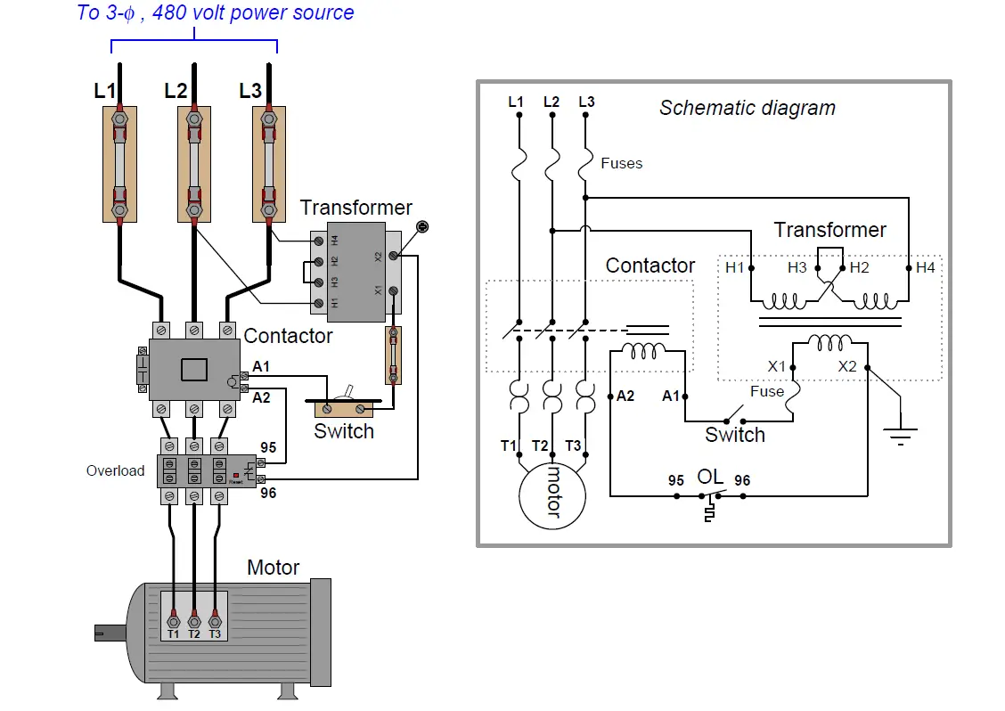
The control circuit is separate from the motor circuit. The control circuit may not be at the same voltage as the power circuit. When the voltage of the control and power circuits is the same, it is referred to as Common Control. If the volt-ages are different, it is called Separate Control. Figure 4. Typical Starter Wiring Diagram — Three-Phase
Motor Control Wiring Diagram Pdf - wiring diagram is a simplified usual pictorial representation of an electrical circuit. It shows the components of the circuit as simplified shapes, and the facility and signal associates with the devices. A wiring diagram usually gives assistance just about the relative point of view and bargain of devices ...
Wiring Diagram Book A1 15 B1 B2 16 18 B3 A2 B1 B3 15 Supply voltage 16 18 L M H 2 Levels B2 L1 F U 1 460 V F U 2 L2 L3 GND H1 H3 H2 H4 F U 3 X1A F U 4 F U 5 X2A R Power On Optional X1 X2115 V ... MOTOR 3CT TO 120 V SEPARATE CONTROL * OT is a switch that opens when an overtemperature condition exists (Type MFO and MGO only) T1 T3 MOTOR 3 2 L2 T2 ...

circuits which allow you to control a servo without using a receiver. Lets look at the signal we need to generate. The voltage on the control line should be 0 Volts for a low signal (logic 0) and 5 Volts for a high signal (logic 1). The voltage to the control line should be a pplied through a 10k resistor to limit the current in case something ...

wiring diagrams used. Motor Control Circuits Motor control circuits are an effective way to reduce cost by using smaller wire and reduced-amperage devices to control a motor. Imagine trying to wire a pushbutton station for a 100A motor using 3 AWG conductors. Many smaller motors use the same size ...
Basic wiring for motor control - Technical data. They show the relative location of the components. They can be used as a guide when wiring the controller. Figure 1 is a typical wiring diagram for a three-phase magnetic motor starter. Figure 1 - Typical Wiring Diagram.

[PDF] AC motor control circuits - Ibiblio · [PDF] Basic Motor Control - SOL*R | - BCcampus · [PDF] Wiring Diagram Book - Daltco Electric · [PDF] Trade of ...
Part 2: Circuit-breakers. Part 3: Switches, disconnectors, switch-discon-nectors and fuse combination units. Part 4: Contactors and motor starters including short circuit and overload protection devices. Part 5: Control circuit devices and switching elements. Part 6: Multiple function equipment such as that used for automatic emergency power ...

This form of electrical diagram is sometimes referred to as a "schematic" or "line" diagram. 5 Ex a m ple s of Cont rol Circ uit s 2- and 3-Wire Control Elementary Diagrams Low Voltage Release and Low Voltage Protection are the basic control circuits encountered in motor control applications.
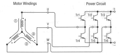
Brushless DC Motor Control Made Easy. AN857 DS00857A-page 2 2002 Microchip Technology Inc. In this example there are three electromagnetic circuits ... electromagnetic circuits. A timing diagram showing the relationship between the sensor outputs and the required motor drive voltages is shown in Figure 2. FIGURE 2: SENSOR VERSUS DRIVE TIMING A +V-V

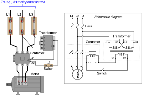
wiring diagram calls for something different. It is your job to improvise a solution! file 00836 Question 4 Interpret this AC motor control circuit diagram, explaining the meaning of each symbol: L1 L2 Run M1 To 3-phase motor power source M1 Also, explain the operation of this motor control circuit. What happens when someone actuates the ...
4 Electric Motor Controls, G. Rockis, 2001 Manual Control Circuits Manual control circuit - any circuit that requires a person to initiate an action for the circuit to operate. A line diagram may be used to illustrate a manual control circuit of a pushbutton

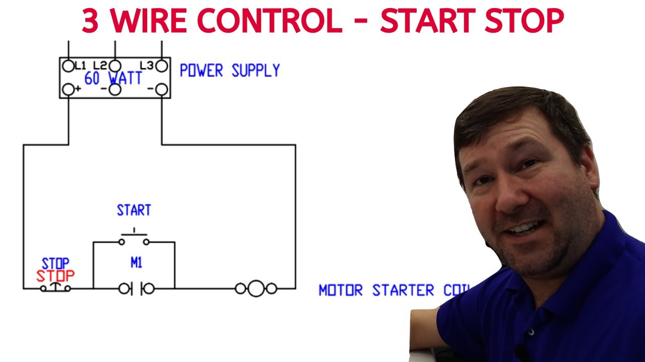
A very common form of latch circuit is the simple "start-stop" relay circuit used for motor controls, whereby a pair of momentary-contact pushbutton switches control the operation of an electric motor. In this particular case, I show a low-voltage control circuit and a 3-phase, higher voltage motor:
The interlock contacts installed in the previous section's motor control circuit work fine, but the motor will run only as long as each push button switch is held down.. If we wanted to keep the motor running even after the operator takes his or her hand off the control switch(es), we could change the circuit in a couple of different ways: we could replace the push button switches with ...
Maxim > Design Support > Technical Documents > Tutorials > Interface Circuits > APP 4697 Keywords: motor control, industrial control, hall effect sensor, DC Motor, brushless DC, AC induction, electrical components, block diagram, TUTORIAL 4697 Overview of Industrial Motor Control Systems By: Sohail Mirza, Application Manager May 10, 2010
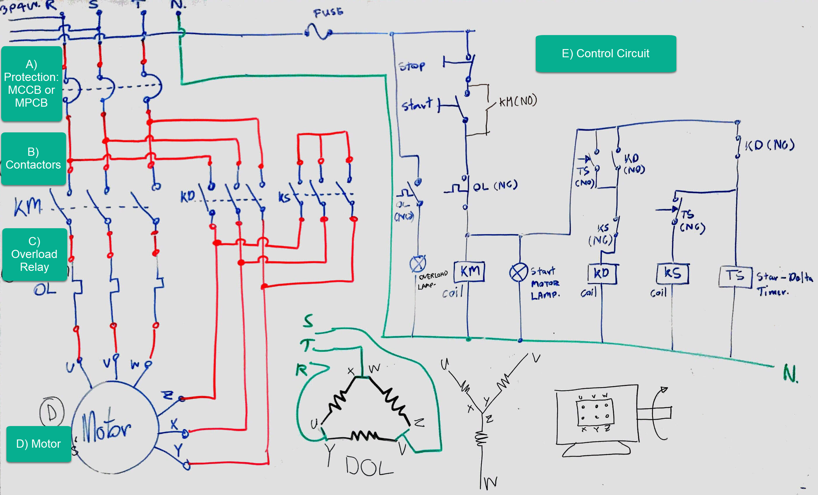
Three phase motor control circuit diagram pdf. The finished project contains electrical diagrams panel mechanical layout and various lists. Star delta y δ 3 phase motor starting method by automatic star delta starter with timer. Three phase motor connection star delta without timer power control diagrams. Phase 1 l2 l4.


0 Response to "40 motor control circuit diagram pdf"
Post a Comment