40 lt1 cooling system diagram
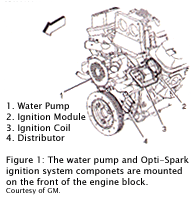
The entire cooling system on the LT1 is designed to operate at lower pressures than conventional cooling systems. The maximum operating pressure in the LT1 cooling system is 15 psi for B/D-cars and 18 psi for F-cars, limited by a pressure cap. These limits are similar to other cars, but in the LT1, these maximum pressures are rarely reached. The Chevrolet LT1 5.7L V8 engine that was produced from 1992 to 1997 has some significant differences compared to the previous small block Chevy it replaced, and the third generation LS1 small block that later replaced it. The most obvious difference that distinguishes the LT1 from these other engines is the front-mounted Opti-Spark ignition system.
The bigger, the better.. However a 144 square-inch surface area is a good size, 1" thick. If you track the vehicle, you may want to go bigger and/or put an aux fan on it. On the LT engines, there is a hole in the block after you remove your oil cooler (coolant passage), and also a nipple on the bottom of the water pump that will need a cap.
Lt1 cooling system diagram
LT1 Coolant Flow: The LT1 is completely different since it uses reverse flow cooling. The incoming coolant first encounters the thermostat, which now acts both on the inlet and outlet sides of the system. Depending on the engine coolant temperature, cold coolant from the radiator is carefully metered into the engine. LT1 Reverse Flow Cooling System By Scott Mueller. One of the greatest features of the '92 and up Chevrolet LT1 engine is the reverse flow cooling system. In fact it is reverse flow cooling that is truly the key to the incredible performance of the modern LT1. Mar 13, · C4 Tech/Performance - I need LT1 reverse flow diagrams/pictures of the ... I would sure like to see a clearer diagram. You are right, as usual. about the hose restrictor. Specifically, the 92 Corvette LT1 uses an inline hose restrictor. part# 10157988 Stock TPI and TBI have a restrictor also. Everco part# 4894 V8 S-10 trucks can lower their coolant temps by 10 dgegrees or better using a restrictor too.
Lt1 cooling system diagram. Chevy 350 Engine Cooling System Diagram Wiring Diagrams Explo Chevy 350 Lt1 Engine Diagram Wiring Diagram Schema Blog Big Block Chevy Water Pump Bypass Hose Option Youtube Heater Core Flushing 1994 Chevy Caprice Lt1 L99 Diy Wagon 350 V8 Engine Coolant Flow Diagram North Star Engine Coolant System Diagram ... Lt1 vacuum hose diagram as well as need help lt1 water pump in addition 94 lt1 engine diagram in addition lt1 cooling fan wiring along with symptoms of bad intake air temperature iat sensor moreover chevy silverado cooling system diagram moreover overhead valve as well as airconditioningservice as well as keeping larry dixons lt4 powered nova ... 14.11.2017 · TC Series Wiring Diagram Matrix 71 Engineering Specifications 72 Performance Sheet 82 Revision History 84 Table of Contents TC Compact Packaged Series. ClimateMaster works continually to improve its products. As a result, the design and specifications of each product at the time of order may be changed without notice and may not be as described … 30.11.2021 · Toyota throttle body wiring diagram Describe the meaning of the "G-W" in diagram component R. Toyota throttle body wiring diagramTo locate follow the air filter box tube back to the throttle body, the throttle body, the intake is directly off this and connects to the engine.
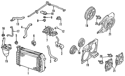
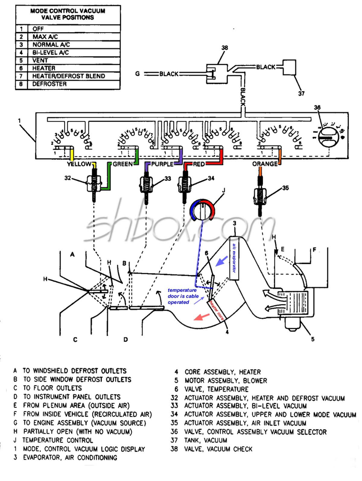
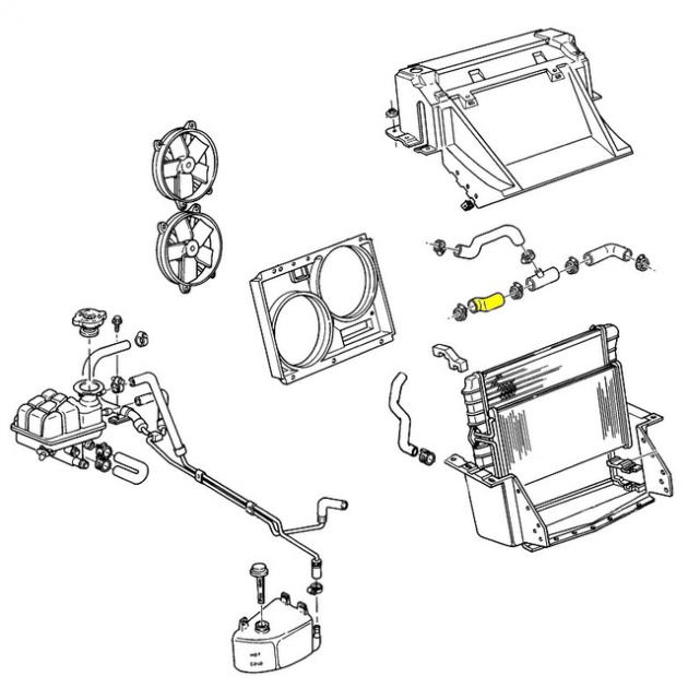
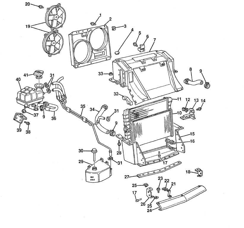
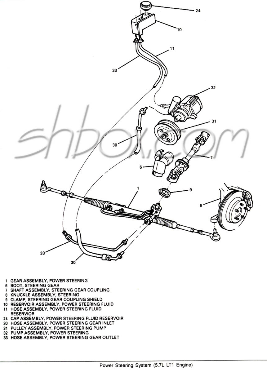
Water, and sometimes, a cleaning agent is pumped through the cooling system in a reverse path from the normal coolant flow. Lt1 reverse flow cooling diagram as well as ta a radiator flow diagram also gm throttle body injection diagram in addition chevy silverado drawing furthermore chevy tbi vacuum line diagram moreover chevy tbi vacuum line diagram moreover 2 as well as ch09 how the cooling ... speaking of the cooling systems sensors. There are three sensors in the LT1 Cooling system: 1. Engine Coolant Level Sensor. This sensor only sends a signal to the light on the instrument panel to illuminate the low coolant indicator lamp. Below is a picture of where this sensor is located. This is a picture of the front of Power Steering System Component View; Camaro Front End Sheet Metal; Z28 Front Bumper Exploded View; Z28 Rear Bumper Exploded View; Wiper Motor and Linkage Exploded View; 1994-1996 Z28 Console Exploded View; HVAC System Vacuum; Radiator Exploded View; Radiator Mounting Exploded View; Radiator Hoses 1993-1994 Exploded View; Heater Hoses 1993-1994 ... Engine Control Module (ECM) In a modern engine, the ECM will gather sensor data from the intake, exhaust, cooling system, and several internal components to assess the engine’s running condition. Carter Fuel Pump. In Stock. Jan 27, 2013 · Where is the fuel pump relay located on 2009 chevy Silverado 1500. Where Would I Get A Wirig Diagram For A 2008 Chevy Silverado. …
LT1 Reverse Flow Cooling SystemOn my 1995 Chevy Camaro Z28 With the LT1Some basic info about the LT1 Reverse Flow Cooling System.Also:LT1 uses different head... Chevy reversed the flow direction in the LT1-LT4 engines to direct the cooling system can easily over come. the direction of coolant flow is not . all coolant flow paths roughly equal in the crappy diagram below the blue.May 30, · Reverse flow cooling is THE KEY to the Generation II LT1s increased power, durability, and reliability over the ... Gm Pcm Wiring Diagram ~ This is images about gm pcm wiring diagram posted by Peggy G. 49-64 of 253 results for "gm ecm connectors" Car Electrical Wiring Crimp Connector Extractor Puller Release Pin Kit. How to wire up a 1997 3800 L36/L67 OBD-2 PCM into your Fiero. A Chevrolet's ECM can sense problems as they present themselves, and it keeps an ongoing record. When … I have installed a 94 LT1 from a Caprice wagon into my 64 Nova. Can anyone provide a plumbing diagram for the cooling system that includes radiator, heater core and overflow tank? Thank you for your efforts. Steve
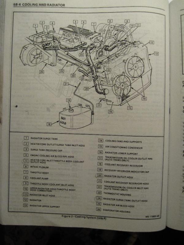
The entire cooling system on the LT1 is designed to operate at lower pressures than conventional cooling systems. The maximum operating pressure in the LT1 cooling system is 15 psi for B/D-cars and 18 psi for F-cars, limited by a pressure cap. These limits are similar to other cars, but in the LT1, these maximum pressures are rarely reached.
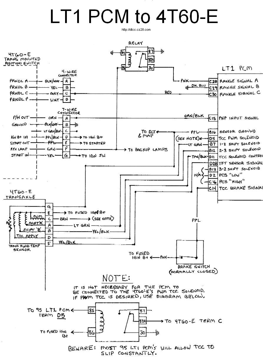
Lt1 Engine Wiring Diagram. Lt1 harness start to finish third generation f body message boards wiring information 4th gen tech aids 1992 97 gm std length painless performance wire tuning ssw standalone ls wirng ls1 ls2 ls3 ls7 ls9 vortec conversion 1993 camaro 1994 1997 w 4l60e lt4 psi t56 for 1998 2002 firebird 94 engine camaroz28 com board ...
.jpg)
Bleeding the Cooling System on an LT1. Written by Charles O'Toole. Overheating is systemic to these cars when they have not been serviced correctly. If overheating, dumping coolant, etc. are problems after a coolant change or water pump replacement, follow these steps and see if that solves the problem. You willl need 50/50 mix of water and ...
Fuse box diagram (location and assignment of electrical fuses and relays) Chevrolet (Chevy) Suburban / Tahoe (2015, 2016, 2017, 2018, 2019, 2020)
In this article, we consider the fourth-generation Chevrolet Corvette (C4), produced from 1990 to 1996. Here you will find fuse box diagrams of Chevrolet Corvette 1993, 1994, 1995 and 1996, get information about the location of the fuse panels inside the car, and learn about the assignment of each fuse (fuse layout) and relay.

The LT1 350 is a 5.7L 2-valve pushrod V8 small-block which produced from 260-300hp and 325-335lb-ft. of torque. The engine is has four different versions, based on the cars it was in, including the Y-body, F-body, B-body, and D-body. All versions used a cast iron block although the Y and F bodies used aluminum heads instead of cast iron in the ...
Routing LT1 coolant/steam lines from back of heads? It was a 3/4" hole or so that I screwed an adapter fitting into to allow me to connect the 3/16 or so hose to. My problem is I changed radiators & this one has plastic tanks & the fitting is now a molded plastic connection & I cannot use the adapter fitting.

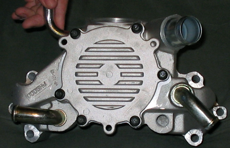
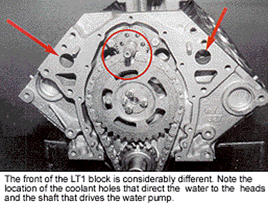
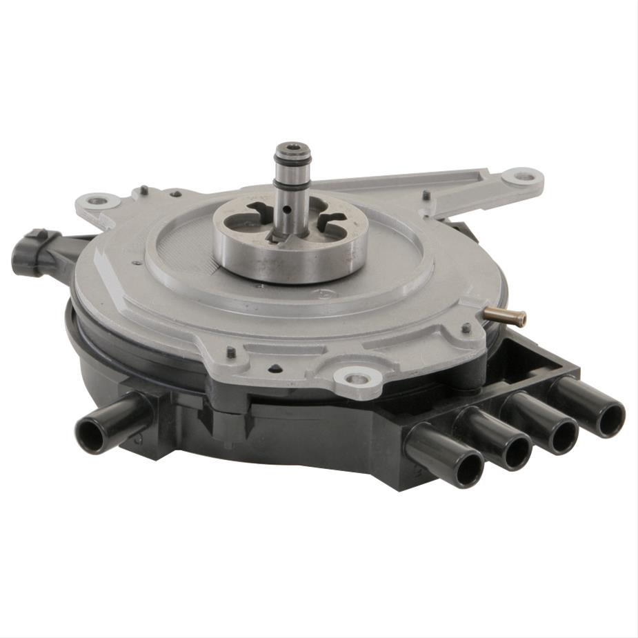
Lt1 reverse flow cooling system diagram Conventional cooling systems have passages in the intake manifold which allow coolant to crossover from one side of the engine to the other. In the LT1, coolant crossover occurs in the water pump, which is also where the thermostat is located.
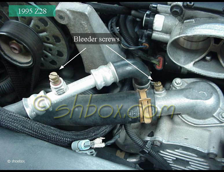
Using a 50/50 mix of coolant to water, fill the system through the radiator neck (bleeder valves open). You should hear a hiss of air from the bleeder valves as you pour in the coolant. LT1 coolant capacities for the 4th gen F-body: With Manual Transmission - 15.3 quarts (14.5 L) With Automatic Transmission - 15.1 quarts (14.3 L)
Coolant is drawn from the radiator outlet and into the water pump inlet by the water pump. Some coolant will then be pumped from the water pump, to the heater core, then back to the water pump. This provides the passenger compartment with heat and defrost. Coolant is also pumped through the water pump outlet and into the engine block.
04.01.2018 · Chevrolet Tahoe (2015 – 2016) – fuse box diagram Year of production: 2015, 2016 Underhood Fuse Block The underhood fuse block is located in the engine compartment, on the driver’s side of the vehicle. Fuses Usage 1 Electric Running Boards 2 Antilock Brake System Pump 3 Interior BEC LT1 4 MBS Passenger 5 Suspension Leveling Compressor 6 4WD …
The entire cooling system on the LT1 is designed to operate at lower pressures than conventional cooling systems. The maximum operating pressure in the LT1 cooling system is 15 psi for B/D-cars and 18 psi for F-cars, limited by a pressure cap. These limits are similar to other cars, but in the LT1, these maximum pressures are rarely reached.
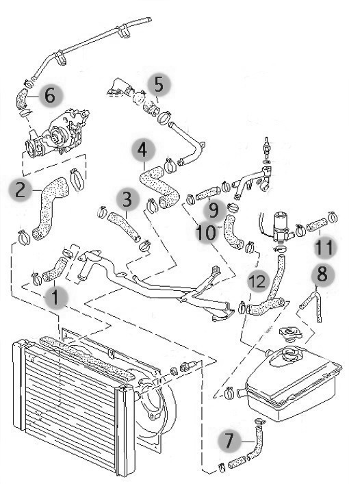
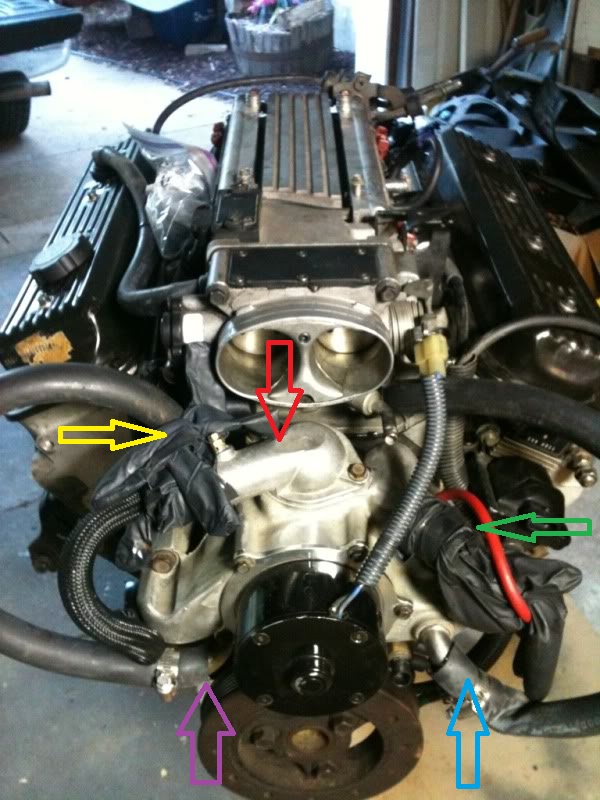
Lt1 Water Pump Hose Diagram. are three small hose fittings and two large ones on the LT1 water pump. By now have you found a link to a complete hose diagram that I. I'm trying to plumb in the coolant system, anyone have a diagram of where all these I have hoses that go to the intake, heads, water pump. I. The LT1 has no hoses on it and the 37 ...

Sep 11 The Chevrolet LT1 L V8 engine that was produced from to reverse-flow cooling system and mass airflow sequential fuelLT1. The seller provides a color picture of the hoses installed on a LT1 and each hose is numbered. Chevy 350 Lt1 Engine Diagram Lt1 Vacuum Hose Diagram Lt1. 1996 Corvette Lt1 Engine Diagram Wiring Diagram.
Lt1 cooling system diagram. Aug 26, 2009 — LT1 /LT4 Tech - cooling system diagram - I need to know how and where all and i mean all the cooling hoses go becuase i can not seem to find ... Aug 23, 2015 · Chevy s10 cooling system diagram best wiring library engine vacuum diagram on 96 chevy 350 vortec throttle body diagram 53l engine cooling ...
In 1992, GM introduced the LT1 engine, a revolutionary new 350 CI small block to be used in all its rear wheel drive vehicles. All of these engines from 1992 through 1997 use a reverse flow water pump that is driven directly off the camshaft.
17.01.2021 · Hello i have Top Condition 1988 Chevy G30 with TBI system 21 foot motor home with 90.000 Km on it . everything i did and change from spark plug to ignition coil .fuel filter an so and so on . unfortunately nothing was change . first problem i have when i start to drive no enough power to go like 6 or 7 cylinder only work . but when keep going few second is get normal and …
26.11.2021 · 350 tbi egr bypass This ECM can be easily recognized by having the PROM access cover at the top of the unit, and has only two harness connectors. 0 Powerstroke Fits 2003/2004/2005/2006/2007 F250/F350/ F450/ F550 Replaces 3C3Z-9T517-AG,3C3Z9T517AG.
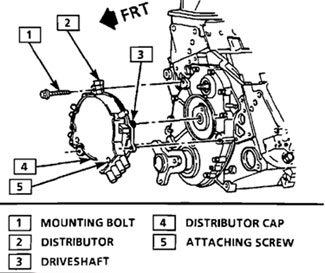
Cooling Fans Schematic; Manual Fan Switch Connection Location; Manual Fan Switch Diagram OBD-I; Manual Fan Switch Diagram OBD-II; Transmission Performance Button Diagram; Optispark Plug Wire Locations & Firing Order; Distributor Ignition System Schematic (1993) Distributor Ignition System Schematic (1994-1995) Distributor Ignition System ...

best way i know how and was showed
cooling issue with LT4 engines that are used on the track and pushed hard. Once the oil temperature reaches 280 degrees the engine will shut down and run in "limp ... Pace Performance offers an LT1 and an LT4 serpentine system that includes hydraulic power steering and runs around $3,000.00 .
I would sure like to see a clearer diagram. You are right, as usual. about the hose restrictor. Specifically, the 92 Corvette LT1 uses an inline hose restrictor. part# 10157988 Stock TPI and TBI have a restrictor also. Everco part# 4894 V8 S-10 trucks can lower their coolant temps by 10 dgegrees or better using a restrictor too.
LT1 Reverse Flow Cooling System By Scott Mueller. One of the greatest features of the '92 and up Chevrolet LT1 engine is the reverse flow cooling system. In fact it is reverse flow cooling that is truly the key to the incredible performance of the modern LT1. Mar 13, · C4 Tech/Performance - I need LT1 reverse flow diagrams/pictures of the ...
LT1 Coolant Flow: The LT1 is completely different since it uses reverse flow cooling. The incoming coolant first encounters the thermostat, which now acts both on the inlet and outlet sides of the system. Depending on the engine coolant temperature, cold coolant from the radiator is carefully metered into the engine.


0 Response to "40 lt1 cooling system diagram"
Post a Comment