40 pure iron phase diagram
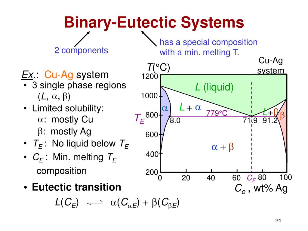
File:Iron carbon phase diagram.svg - Wikimedia Commons English: Iron-carbon phase diagram under atmospheric pressure. This diagram is limited by pure iron on the left and by iron carbide on the right. The mains phases are: * iron: ferrite, ferritic steel * iron: austenite, austenitic steel * iron carbide: cementite, Fe3C. We can see a eutectic and a eutectoid; these phases crystallise as a stacking ... Phase Diagram: Meaning and Types | Material Engineering (α + β) phase constitutes of pure copper and pure silver. iv. Below line CEG (779°C), there is only partial solubility of Ag in Cu (α phase) and Cu in Ag (β-phase). ... Relationship between the Phase Diagram and Properties of Material: i. Fluidity is maximum for pure material at eutectied. ... By increase in percentage of carbon in iron ...
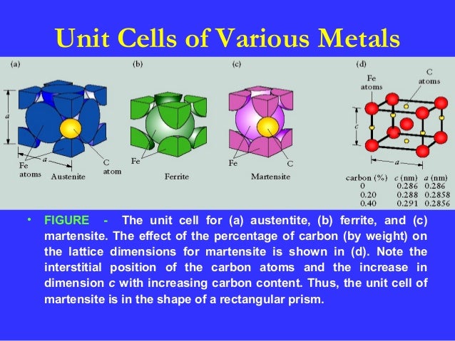
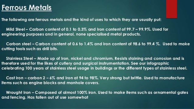
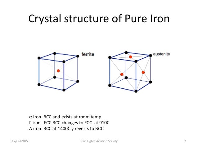
Phase Diagrams.docx - Chapter 9: Phase Diagrams Definitions... Iron-Carbon System Iron - iron Carbide phase Diagram: - Pure iron, upon heating, experiences two changes in crystal structure before it melts. At room temperature, the stable form, called ferrite (interstitial solid solution of carbon) has a BCC crystal structure.

Pure iron phase diagram
Pure iron - the phase diagram - terapascal pressures, 20000 K - YouTube Recent work has extended the diagram with some surprising results, showing that hcp iron is not necessarily the most stable form at terapascal pressures and temperatures as high as 20,000 K. The... Solved The following figure is the phase diagram of pure - Chegg The following figure is the phase diagram of pure iron, which indicates the equilibrium phase (s) of iron for various conditions of temperature and pressure. α-Fe (alpha iron) denotes a BCC form of iron, whereas γ-Fe (gamma iron) denotes an FCC form of iron. Ambient pressure of 1 atm is approximately 1.01 bar. Therefore, ambient pressure Iron-Iron Carbide Phase Diagram | Material Engineering The Iron-Iron carbide (Fe-Fe 3 C) is defined by five individual phases and four invariant reactions. Five phases are- α-ferrite (BCC) Fe-C solid solution, γ-austenite (FCC) Fe-C solid solution, δ -ferrite (BCC) Fe-C solid solution, Fe 3 C (iron carbide) or cementite - an inter- metallic compound and liquid Fe-C solution.
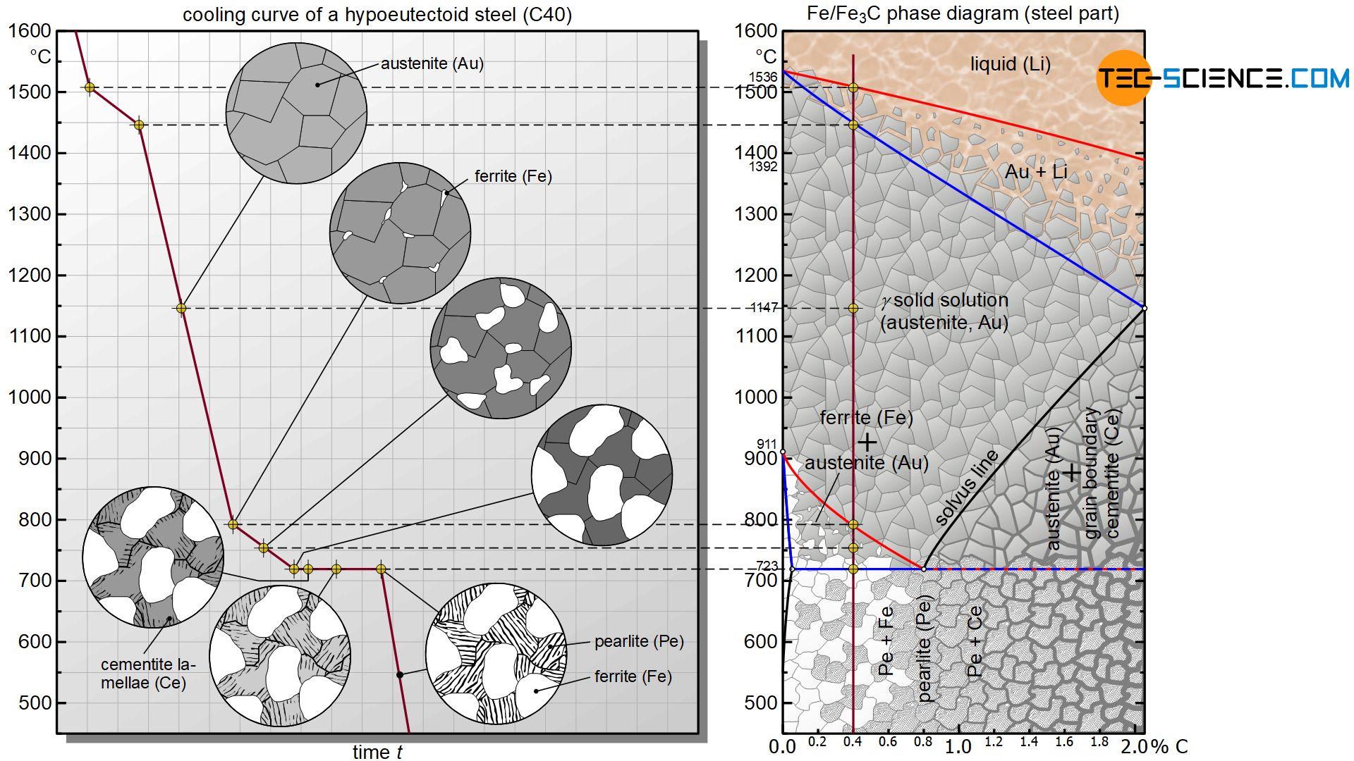
Pure iron phase diagram. Microstructure formation of steels during solidification Therefore, the phase diagram of the iron/carbon alloy system is somewhat more complex. In order to understand the microstructural processes inside a steel, it makes sense to first take a closer look at the microstructure formation of pure iron. For this reason, the cooling curve of iron is discussed in more detail in the following section. ... Iron-Manganese - Metallurgy for Dummies Phase Diagrams Fe-Mn, Fe-Co, Fe-Mo In pure iron, the A4 (1394 °C) and A3 (912 °C) transformations take place at constant temperatures. If an element enters into solid solution in iron — forming in that way a binary alloy — each of these transformations are required by the Phase Rule to occur over a range of temperature. Iron-Carbon Diagram Explanation [PDF] - Mechanical E-Notes Iron-Carbon Phase Diagram with Detailed Explanation: If the percentage of the carbon is in the range of 0 to 2.11 % then it is called Steel and if the percentage of carbon is in the range of 2.11 to 6.67% then it is called Cast iron. As the carbon content increases, it produces more Iron-Carbide volume and that phase will exhibit high hardness. Solved Pure iron (Fe) undergoes an allotropic transformation - Chegg Pure iron (Fe) undergoes an allotropic transformation at 912°C. Upon heating from a BCC (a ferrite phase) to an FCC (y austenite phase), this transformation is accompanied by a change in density (and volume). ... The iron - iron carbide phase diagram is shown below 1600 1493°C L 1400 1200 1000 Temperature (°C) 1538°C 8 1394°C Y, Austenite ...
PDF 10. Phase diagrams - Campus Tour Accordingly, the phase diagram for pure iron may be drawn on a temperature coordinate only, as in Figure 2. We know that the free energy of the crystallographic form stable within a particular temperature range must be less than that of any other form. Phase Diagram - Metallurgy for Dummies Phase Diagram Phase Diagrams Fe-Mn, Fe-Co, Fe-Mo In pure iron, the A4 (1394 °C) and A3 (912 °C) transformations take place at constant temperatures. If an element enters into solid solution in iron — forming in that way a binary alloy — each of these transformations are required by the Phase Rule to occur over a range of temperature. PDF IRON CARBON PHASE DIAGRAM - Higher Technological Institute Iron- Carbon diagram shows - the type of alloys formed under very slow cooling, proper heat-treatment temperature and how the properties of steels and cast irons can be radically changed by heat-treatment. Cooling curve for pure iron Various Features of Fe-C diagram Max. solubility of C in ferrite=0.022% Max. solubility of C in %austenite=2% PDF Fe-C Phase Diagram - University of Babylon Fe-Fe3C Phase Diagram • Only part of the phase diagram is shown. • The left axis is pure iron. • On the right the phase diagram only extends to 6.70 wt%C • At this concentration the intermediate compound iron carbide, or cementite (Fe3C) is formed 4 Austenite γ α+ Fe3C Development of Microstructures in Iron-Carbon Alloys γ⇒α+Fe3C ...
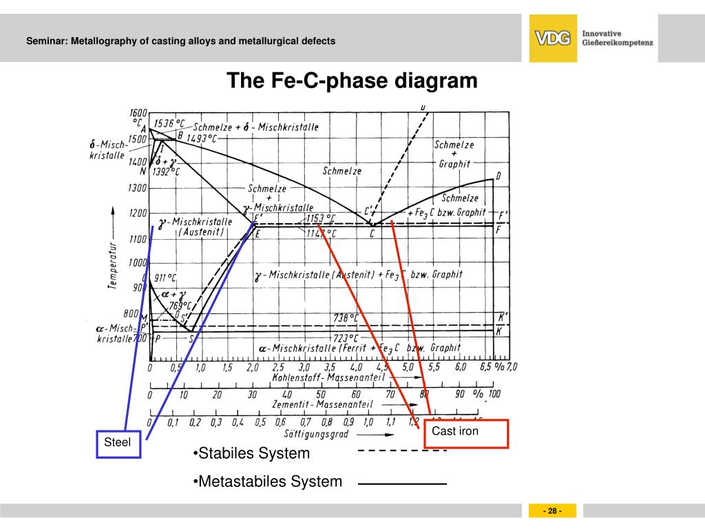
Iron iron-carbide phase diagram - SlideShare THE IRON-IRON CARBIDE DIAGRAM The diagram shows three horizontal lines which indicate isothermal reactions (on cooling / heating): First horizontal line is at 1490°C, where peritectic reaction takes place: Liquid + d ↔ austenite Second horizontal line is at 1130°C, where eutectic reaction takes place: liquid ↔ austenite + cementite Third ... Pure Iron - an overview | ScienceDirect Topics Pure ironmolybdate (Fe2MoO4) was tested both in argon and in air atmosphere while heating up to 1573 K with 10 K/min rate. The results are shown in Figure 3.1.17. During heating in air, Fe2MoO4is subjected to oxidation, which starts after 573-673 K and results in the mass increase followed by decrease. The Iron-Carbon Alloys And Fe-C Phase Diagram - ML - Engineering The iron-carbon phases and phase diagram is slightly complex, compared with other diagrams. The horizontal axis of the Fe-C diagram shows the percentage of carbon inside the Fe-C systems. The solubility limit of carbon inside the iron is very low. So the diagram above shows up to 6.11% of carbon content which is also the solubility limit of ... Iron-Carbon Phase Diagram Explained [with Graphs] - Fractory The weight percentage scale on the X-axis of the iron carbon phase diagram goes from 0% up to 6.67% Carbon. Up to a maximum carbon content of 0.008% weight of Carbon, the metal is simply called iron or pure iron. It exists in the α-ferrite form at room temperature. From 0.008% up to 2.14% carbon content, the iron carbon alloy is called steel.
Iron Carbon Phase Diagram and Heat Treatment of Steels - YouTube
What is the Iron-Carbon Phase Diagram? - Engineering Choice The Fe - C diagram (also called the iron-carbon phase or equilibrium diagram) is a graphic representation of the respective microstructure states of the alloy iron-carbon (Fe-C) depending on temperature and carbon content. To explain this diagram, an introduction about metal structures and pure iron must be done.

Carbon - New World Encyclopedia
Phase Diagram Of Pure Iron (हिन्दी ) - YouTube On this channel you can get education and knowledge for general issues and topics
Phase transformations of steels in solidified state (metastable system ...
The Iron-Carbon Phase Diagram - IspatGuru Fig 1 Iron carbon phase diagram. C is an interstitial impurity in Fe. It forms a solid solution with alpha, gamma and delta phases of iron. Maximum solubility of C in alpha iron is 0.025 % at 727 deg C. Body centred cubic (BCC) iron has relatively small interstitial positions. Maximum solubility of C in the face centred cubic (FCC) gamma iron ...

Geos 306, Fall 2013, Lecture 13, Mineralogy of the Earth and its Core
Allotropes of iron - Wikipedia Low-pressure phase diagram of pure iron. BCC is body centered cubic and FCC is face-centered cubic. Iron-carbon eutectic phase diagram, showing various forms of Fe x C y substances. Iron allotropes, showing the differences in structure. The alpha iron (α-Fe) is a body-centered cubic (BCC) and the gamma iron (γ-Fe) is a face-centered cubic (FCC).
Solved: The Iron-iron Carbide Phase Diagram (a) And Its De... | Chegg.com
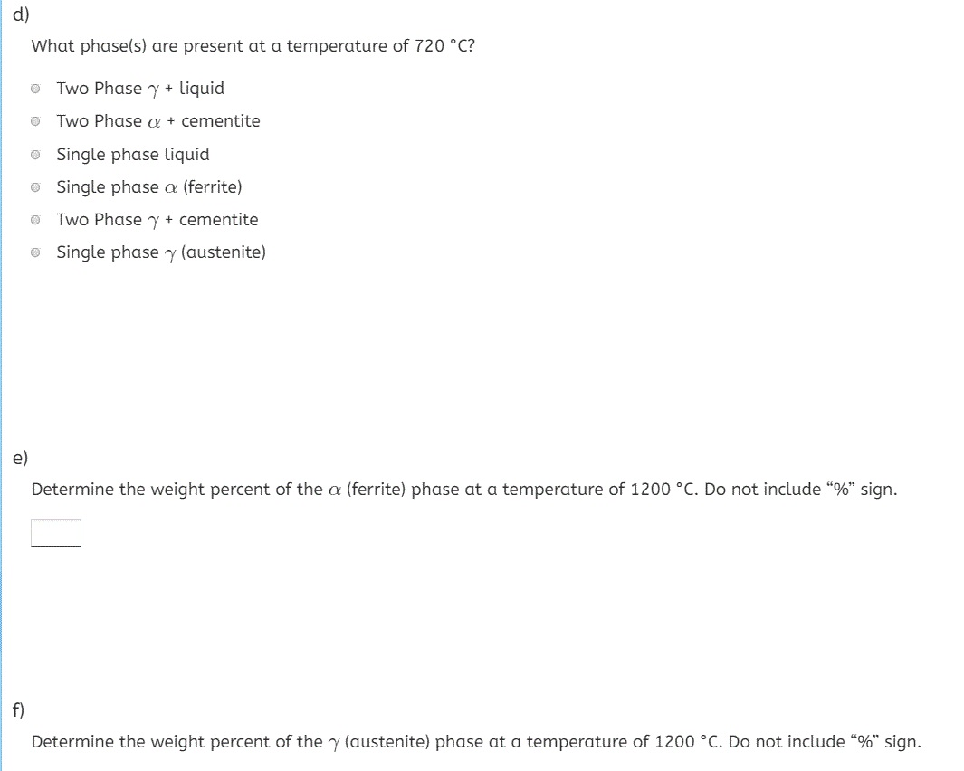
PDF The iron-iron carbide (Fe-Fe3C) phase diagram • Phase diagrams are useful tools to determine:--the number and types of phases,--the wt% of each phase,--and the composition of each phase for a given T and composition of the system. • Alloying to produce a solid solution usually--increases the tensile strength (TS)--decreases the ductility. • Binary eutectics and binary eutectoids ...
Iron iron carbon equilibrium diagram
Phase Diagram - Industrial Metallurgists The phase diagram indicates that an iron-carbon alloy with 0.5% carbon held at 900 °C will consist of austenite, and that the same alloy held at 650 °C will consist of ferrite and cementite. Furthermore, the diagram indicates that as an alloy with 0.78% carbon is slow cooled from 900 °C, it will transform to ferrite and cementite at about ...

Iron Carbon Ttt Diagram
Carbon Steels and the Iron-Carbon Phase Diagram - IspatGuru The Fe- C phase diagram is shown in Fig 2. In pure iron, austenite transforms to ferrite on cooling to 912 deg C. This transition temperature is traditionally called the A3 temperature, and the diagram shows that adding C to Fe lowers the A3 temperature.

Ice-i Research
File:Pure iron phase diagram (EN).svg - Wikimedia Commons Original upload log []. This image is a derivative work of the following images: File:Diagramma_di_fase_del_ferro_puro.svg licensed with Cc-by-sa-3.0, GFDL . 2010-09-11T13:37:42Z Daniele Pugliesi 470x450 (23026 Bytes) piccole correzioni sui valori; 2010-09-11T11:59:22Z Daniele Pugliesi 470x450 (23026 Bytes) Correggo errore: si parla di ferrite solo se è presente carbonio, questo diagramma si ...

Experimental determination of the electrical resistivity of iron at ...
PDF ISSUES TO ADDRESS - Hacettepe PHASE DIAGRAMS: Composition of Phases •a Tt A=1175 C, again only one, solid phase exists with composition: 35 wt % Ni - 65 % Cu •a Tt B=1250 C, two phase (L and α) exist with compositions: L - 32 wt% Ni - 68%Cu α- 43 wt% Ni - 57%Cu Tie line is an isotherm in the two-phase region. Intersects of this line with phase boundary lines (e.g.
PPT - Fundamentals of solidification PowerPoint Presentation, free ...
Iron Carbon Equilibrium Diagram with Explanation [Phase Diagram] The Iron carbon equilibrium diagram (also called the iron carbon phase diagram) is a graphic representation of the respective microstructure states of the alloy iron - carbon (Fe-C) depending on temperature and carbon content. The iron carbon phase diagram is commonly used to fully understand the various phases of steel and cast iron.

Science of Alloying
Iron-Iron Carbide Phase Diagram | Material Engineering The Iron-Iron carbide (Fe-Fe 3 C) is defined by five individual phases and four invariant reactions. Five phases are- α-ferrite (BCC) Fe-C solid solution, γ-austenite (FCC) Fe-C solid solution, δ -ferrite (BCC) Fe-C solid solution, Fe 3 C (iron carbide) or cementite - an inter- metallic compound and liquid Fe-C solution.
PPT - Phase Diagrams Binary Eutectoid Systems Iron-Iron-Carbide Phase ...
Solved The following figure is the phase diagram of pure - Chegg The following figure is the phase diagram of pure iron, which indicates the equilibrium phase (s) of iron for various conditions of temperature and pressure. α-Fe (alpha iron) denotes a BCC form of iron, whereas γ-Fe (gamma iron) denotes an FCC form of iron. Ambient pressure of 1 atm is approximately 1.01 bar. Therefore, ambient pressure
Iron phase diagram by zahid
Pure iron - the phase diagram - terapascal pressures, 20000 K - YouTube Recent work has extended the diagram with some surprising results, showing that hcp iron is not necessarily the most stable form at terapascal pressures and temperatures as high as 20,000 K. The...

Iron-Carbon Equilibrium Phase Diagram ... | Materials engineering ...
Heat treatment
0 Response to "40 pure iron phase diagram"
Post a Comment