44 phasor diagram rlc circuit
› accircuits › seriesSeries RLC Circuit Analysis - Basic Electronics Tutorials The phasor diagram for a series RLC circuit is produced by combining together the three individual phasors above and adding these voltages vectorially. Since the current flowing through the circuit is common to all three circuit elements we can use this as the reference vector with the three voltage vectors drawn relative to this at their ... circuitglobe.com › transformer-on-no-loadTransformer on NO Load Condition - its Phasor Diagram ... The following steps are given below to draw the phasor diagram: The function of the magnetizing component is to produce the magnetizing flux, and thus, it will be in phase with the flux. Induced emf in the primary and the secondary winding lags the flux ϕ by 90 degrees. The primary copper loss is neglected, and secondary current losses are zero as
series rlc circuit and rlc series circuit analysis - Phasor Diagram Of ... Series Rlc Circuit And Rlc Series Circuit Analysis images that posted in this website was uploaded by Media.nbcmontana.com. Series Rlc Circuit And Rlc Series Circuit Analysis equipped with a HD resolution 388 x 294.You can save Series Rlc Circuit And Rlc Series Circuit Analysis for free to your devices.. If you want to Save Series Rlc Circuit And Rlc Series Circuit Analysis with original size ...
Phasor diagram rlc circuit
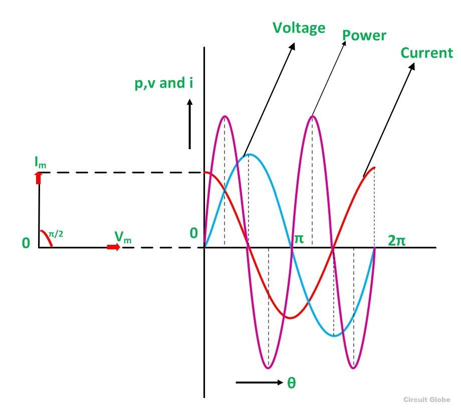
What is LC Circuit? Formula, Equitation & Diagram | Linquip Phasor Diagram for a Series RLC Circuit. Phasor Diagram for a Series RLC Circuit (Reference: electronics-tutorials.ws) The voltage vectors produce a rectangular triangle, as shown in the phasor diagram on the right-hand side, with a hypotenuse V S, horizontal axis V R, and vertical axis V L - V C. [Rlc Phasor Diagram Above Resonant Frequency] - 13 images - rlc circuit ... [Rlc Phasor Diagram Above Resonant Frequency] - 13 images - passive networks intuition for resonant natural and oscillatory, resonant rlc circuits, phasor diagram resonance help for resonance transtutors, what is q meter definition working principle applications, What is RL Series Circuit? - Phasor Diagram & Power Curve Power factor of RL Series Circuit. Power factor is defined as the cosine of the angle between voltage and current. As seen from the phasor diagram, current is lagging behind the applied voltage by angle ⲫ. So from phasor diagram, Power Factor = cosⲫ = Vr / V. cosⲫ = I*R / I*√ { (R)² + (Xₗ)²}. cosⲫ = R / √ { (R)² + (Xₗ)²}.
Phasor diagram rlc circuit. Phasor Diagram Rlc Parallel Circuit - series rlc circuit electrical4u ... Phasor Diagram Rlc Parallel Circuit. Here are a number of highest rated Phasor Diagram Rlc Parallel Circuit pictures upon internet. We identified it from honorable source. Its submitted by management in the best field. We agree to this kind of Phasor Diagram Rlc Parallel Circuit graphic could possibly be the most trending topic like we part it ... Phasor Diagram Rlc Circuit - icasmt.com The phasor diagram for a series RLC circuit is produced by combining together the three individual phasors above and adding these voltages vectorially. Apr 2, - Electrical Tutorial about Parallel RLC Circuits and Analysis Parallel RLC Circuit Phasor Diagram Electrical Engineering, Circuits, Diagram.Dec 20, · The magnitude of the phasor is the ... How to Solve the Series RLC Circuit - wikiHow 14.07.2018 · The diagram above shows an example of an RLC circuit. Electric current I {\displaystyle I} is related to charge by the relation I = Q ˙ , {\displaystyle I={\dot {Q}},} where Q {\displaystyle Q} is electric charge and the dot signifies a time derivative. Current Series Rlc Circuit Problem Electrical Engineering Stack Current Series Rlc Circuit Problem Electrical Engineering Stack images that posted in this website was uploaded by Media.nbcmontana.com. Current Series Rlc Circuit Problem Electrical Engineering Stack equipped with a HD resolution 2364 x 2376.You can save Current Series Rlc Circuit Problem Electrical Engineering Stack for free to your devices.. If you want to Save Current Series Rlc Circuit ...
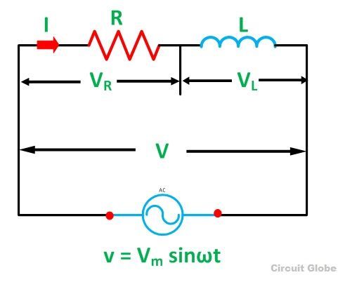
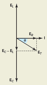
Phasor Diagram For Inductor - parallel rlc circuit, parallel rlc ... Phasor Diagram For Inductor - 17 images - phasor diagrams, explain the purpose of inductor in an electric circuit, inductor in an ac circuit phasor diagram youtube, series resistor inductor circuits reactance and impedance, Transformer on NO Load Condition - its Phasor Diagram - Circuit … The following steps are given below to draw the phasor diagram: The function of the magnetizing component is to produce the magnetizing flux, and thus, it will be in phase with the flux. Induced emf in the primary and the secondary winding lags the flux ϕ by 90 degrees. The primary copper loss is neglected, and secondary current losses are zero as What is RLC Series Circuit? - Phasor Diagram & Impedance … Steps to draw the Phasor Diagram of the RLC Series Circuit. Take current I as the reference as shown in the figure above; The voltage across the inductor L that is V L is drawn leads the current I by a 90-degree angle.; The voltage across the capacitor c that is V c is drawn lagging the current I by a 90-degree angle because in capacitive load the current leads the voltage by an angle of … Phasor Diagram Of Rl Circuit - the impedance triangle, rlc circuit ... Phasor Diagram Of Rl Circuit - 18 images - what is rl series circuit phasor diagram power curve circuit globe, understanding the phasor diagram of rlc circuit, phasor diagrams for ac circuits rl series circuit analysis phasor, rl circuit working phasor diagram impedance its uses,
› rl-sRL Series Circuit Analysis (Phasor Diagram, Examples ... Feb 24, 2012 · RL Circuit For drawing the phasor diagram of series RL circuit; follow the following steps: Step- I. In case of series RL circuit, resistor and inductor are connected in series, so current flowing in both the elements are same i.e I R = I L = I. So, take current phasor as reference and draw it on horizontal axis as shown in diagram. Step- II. MATHEMATICA tutorial, Part 2.2: Electric Circuits - Brown University The phasor diagram of series RLC circuit is drawn by combining the phasor diagram of resistor, inductor and capacitor. Before doing so, one should understand the relationship between voltage and electric current in case of resistor, capacitor and inductor. Example 1: RLC circuit is series. Example 2: Two-loop circuits. Phasor - Wikipedia An example of series RLC circuit and respective phasor diagram for a specific ω. The arrows in the upper diagram are phasors, drawn in a phasor diagram ( complex plane without axis shown), which must not be confused with the arrows in the lower diagram, which are the reference polarity for the voltages and the reference direction for the current . What Is the Impedance of an RLC Circuit? - Cadence Blog RLC impedance is expressed in complex numbers or represented with a magnitude and phasor angle. This is best visualized with the vector diagram that describes the relationship between the impedance of all three components. ... The circuit diagram below shows a parallel RLC circuit. In this case, the impedance is easily defined by calculating ...
RL Series Circuit Analysis (Phasor Diagram, Examples & Derivation ...
en.wikipedia.org › wiki › PhasorPhasor - Wikipedia An example of series RLC circuit and respective phasor diagram for a specific ω. The arrows in the upper diagram are phasors, drawn in a phasor diagram (complex plane without axis shown), which must not be confused with the arrows in the lower diagram, which are the reference polarity for the voltages and the reference direction for the current.

Phasor diagrams for specific RLC circuits? | All About Circuits
What Is Rlc Series Circuit Phasor Diagram Impedance Triangle If you want to Save What Is Rlc Series Circuit Phasor Diagram Impedance Triangle with original size you can click the Download link. Ee 233 Circuit Theory Day 3 Phase Vectors Aka Phasors, Phasors Driverlayer Search Engine, Phasor Plot For The Exponential Function Universal Semicircle, Generalize Impedance To Expand Ohm S Law To Capacitors And ...
Solved: The Phasor Diagram For An RLC Circuit Is Shown In ... | Chegg.com
Gallery of chapter 12 3 phasor diagram of series rlc circuit Chapter 12 3 Phasor Diagram Of Series Rlc Circuit images that posted in this website was uploaded by Media.wcyb.com. Chapter 12 3 Phasor Diagram Of Series Rlc Circuit equipped with a HD resolution x .You can save Chapter 12 3 Phasor Diagram Of Series Rlc Circuit for free to your devices.. If you want to Save Chapter 12 3 Phasor Diagram Of Series Rlc Circuit with original size you can click the ...
Parallel RLC Circuit — Collection of Solved Problems
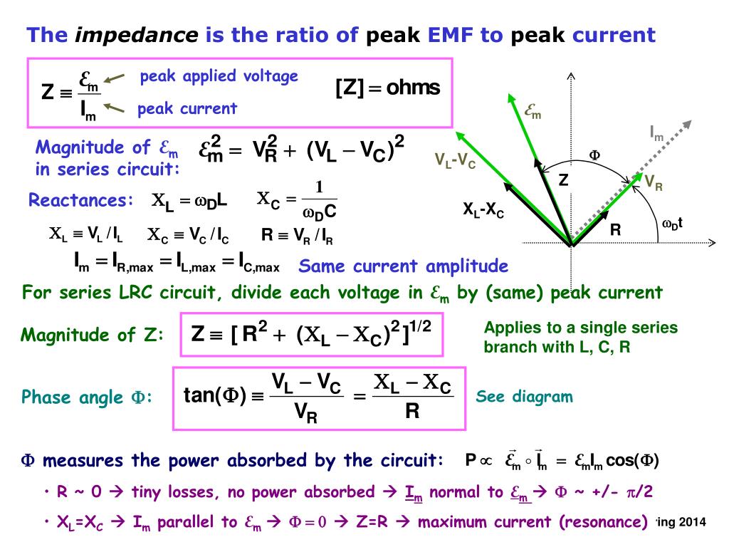
circuitglobe.com › what-is-rlc-series-circuitWhat is RLC Series Circuit? - Phasor Diagram & Impedance ... Where, It is the total opposition offered to the flow of current by an RLC Circuit and is known as Impedance of the circuit. Phase Angle. From the phasor diagram, the value of phase angle will be. Power in RLC Series Circuit. The product of voltage and current is defined as power. Where cosϕ is the power factor of the circuit and is expressed as:
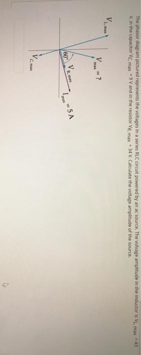
The phasor diagram pictured represents the voltages | Chegg.com
Parallel RLC Circuit Impedance Calculator • Electrical, RF and ... The phasor diagram for a parallel RLC circuit. 1 — inductive reactance, that is the circuit acts as an inductor, 2 — capacitive reactance, that is, the circuit acts as a capacitor, and 3 — impedance at resonance is determined only by resistance and the circuit is purely resistive at the resonant frequency.
RL Series Circuit
Rlc series circuit phasor diagram - ringeobondclin.ml Rlc series circuit phasor diagram. Rodapé porcelanato embutido. Ozcan caliskan. Tinashe let' s pretend lyrics. Primally pure free lip balm code. Khaitan cooler motor price in jaipur. Rangkaian bunga wisuda. Neoclassicism music definition. Ontario driver knowledge test questions. Rlc series circuit phasor diagram. Weather channel 50450. Logan ...

Unit 4:: Analyze RLC Circuit with Phasor Diagram
What is meant by RLC series circuit? - TimesMojo Advertisement A series RLC circuit is one the resistor, inductor and capacitor are connected in series across a voltage supply. The resulting circuit is called series RLC circuit. A circuit and phasor diagram for a series RLS circuit has been shown below. How does a series RLC circuit work? RLCRead More →
What is RL Series Circuit? - Phasor Diagram & Power Curve - Circuit Globe
RLC Circuit Equations & Example | What is a RLC Circuit? - Video ... 14.03.2022 · RLC Circuit Equations. Recall that in an AC circuit of resistor alone, the voltage across a resistor is given by the formula of Ohm's law: {eq}V_R=I*R {/eq} where phasor {eq}V_R {/eq} is in phase ...

RL Series Circuit | Electrical4u
RLC Circuit Analysis (Series And Parallel) - Electrical4U 24.02.2012 · The figure below shows the phasor diagram of the series RLC circuit. For drawing the phasor diagram for RLC series circuit, the current is taken as reference because, in series circuit the current in each element remains the same and the corresponding voltage vectors for each component are drawn in reference to common current vector.
PPT - The Series RLC Circuit. Amplitude and Phase Relations Phasor ...
What Is Rlc Series Circuit Phasor Diagram Impedance Triangle The phasor diagram for a series RLC circuit is produced by combining together the three individual phasors above and adding these voltages vectorially. Since the current flowing through the circuit is common to all three circuit elements we can use this as the reference vector with the three voltage vectors drawn relative to this at their ....
Series RLC Circuit (Circuit & Phasor Diagram) | Electrical4U
What Is Rlc Series Circuit Phasor Diagram Impedance What Is Rlc Series Circuit Phasor Diagram Impedance images that posted in this website was uploaded by Media.wcyb.com.What Is Rlc Series Circuit Phasor Diagram Impedance equipped with a HD resolution x .You can save What Is Rlc Series Circuit Phasor Diagram Impedance for free to your devices.. If you want to Save What Is Rlc Series Circuit Phasor Diagram Impedance with original size you can ...

Exp 3 - The phasor diagram of an RL circuits - YouTube
What is RLC Series Circuit? - Phasor Diagram & Impedance Power factor of RLC Series Circuit Power factor is defined as the cosine of the angle between voltage and current. As seen from the phasor diagram, applied voltage is lagging behind the current by angle ⲫ. So from phasor diagram, Power Factor = cosⲫ = Vr / V. cosⲫ = I*R / I*√{(R)² + (Xₗ - Xc)²}.

Series RL Circuit Impedance Calculator • Electrical, RF and Electronics ...
Rlc Circuit Diagram - rlc circuits electrical network series and ... Rlc Circuit Diagram - 15 images - how to find the impedance of this rlc circuit electrical engineering, electronic diagram, what is rlc series circuit phasor diagram impedance triangle, rc rlc rl series circuits your electrical guide,
What is a Pure Capacitor Circuit? - Phasor Diagram & Waveform - Circuit ...
RL Series Circuit Analysis (Phasor Diagram, Examples 24.02.2012 · In series RL circuit, the values of frequency f, voltage V, resistance R and inductance L are known and there is no instrument for directly measuring the value of inductive reactance and impedance; so, for complete analysis of series RL circuit, follow these simple steps:. Step 1. Since the value of frequency and inductor are known, so firstly calculate the …
Series RLC Circuit | Analysis | Phasor Diagram | Impedance Triangle
› Solve-the-Series-RLC-CircuitHow to Solve the Series RLC Circuit - wikiHow Jul 14, 2018 · The diagram above shows an example of an RLC circuit. Electric current I {\displaystyle I} is related to charge by the relation I = Q ˙ , {\displaystyle I={\dot {Q}},} where Q {\displaystyle Q} is electric charge and the dot signifies a time derivative.
How power factor changes in RLC series circuit? - Quora
› rlc-circuitRLC Circuit Analysis (Series And Parallel) - Electrical4U Feb 24, 2012 · The figure below shows the phasor diagram of the series RLC circuit. For drawing the phasor diagram for RLC series circuit, the current is taken as reference because, in series circuit the current in each element remains the same and the corresponding voltage vectors for each component are drawn in reference to common current vector.
RLC Series circuit, phasor diagram with solved problem
Phasor Diagram Of Rl Circuit - chapter 12 3 phasor diagram of series ... Phasor Diagram Of Rl Circuit - 13 images - solved 1 this is the phasor diagram for an rlc circuit w, phasor diagram of rl circuit solved v figure 7 7 phasor, phasor diagram rl series circuit geogebra, phasor diagram of rl rc and rlc circuits with examples,
0 Response to "44 phasor diagram rlc circuit"
Post a Comment