38 pressure tank plumbing diagram
Parts of a Toilet - Toilet Tank Diagram - Best Home Gear 24/08/2022 · If additional pressure closes off the tank and stops the toilet from running, the flapper probably needs to be replaced. Like any other moving part, flappers wear out over a while, eventually preventing them from sealing properly. Replace Toilet Flapper: To replace the flapper, start by turning off the water to your toilet and draining the ... toilethaven.com › 2020/03/05 › parts-of-a-toilet-tankToilet Tank Parts: Plumbing Diagram, Pictures, Repairs Mar 05, 2020 · Replacing the toilet tank to bowl gasket also involves the complete removal of the toilet tank. Read more here. 8. Toilet tank bolts. Toilet tank bolts are also supplied with nuts, steel and rubber washers. They are used to mount the toilet tank to the toilet bowl.
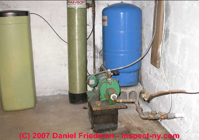
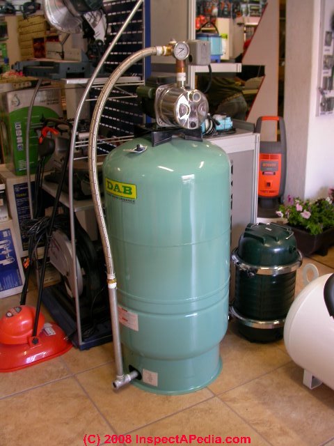
Well Pressure Tank Piping Layout - DoItYourself.com I know you have to check the pressure off the valve stem on top with the tank empty. Cut the power to the pump and drain the tank completely. Your air pressure should be 2 psi below the cut in pressure, so if your pump kicks on at 20 psi, you want 18 psi air in the tank. Got that info here. How to Check the Bladder in a Well-X-Trol Tank | eHow.com
Pressure tank plumbing diagram
CaravansPlus | Caravan Water Pressure & Temp. Control Buy the best range of Caravan Water Pressure & Temp. Control in Australia. Shop for all Caravan Pump, Filter & Accumulator online at Caravans Plus. Choices include One Way Valve, Accumulator & Dampener, Pressure Valve, Pressure Reduction, Temperature Control, and more.You'll get a good deal on leading brands including Atwood, Fiamma, John Guest, … Plumbing Diagrams - Winnebago Plumbing Diagrams. Please choose a year from the menu at the left to start your search. creationsconseilsmorana.com › en › what-is-aHow to make a swimming pool plumbing diagram? For what purpose? Apr 07, 2020 · It must be calibrated according to the volume of the pool. Any pressure losses due to the difference in height or the distance between the pool and the pump room must be considered. The filter. The water pushed by the pool pump flows through this tank filled with a filter medium and comes out of it free of all impurities.
Pressure tank plumbing diagram. PDF TYPICAL SUBMERSIBLE PUMP INSTALLATION - Grover Electric The air level in the tank should be 2 lbs. less than pressure switch turn-on level. For a 30-50 switch, this would be 28 lbs. of air with the tank dry. 2. Use a pressure switch featuring a low-pressure cut-out for wells of low or unknown production. 3. WARNING! A pressure relief valve is required by plumbing code and should be PDF Plumbing Systems of Agricultural Sprayers - Virginia Tech manual throttling valve to regulate major pressure changes while the electric regulating valve can be used to "fine tune" nozzle pressure from the operator's platform. Following are operational guidelines for using a spraying system with a centrifugal pump: Figure 2. Plumbing diagram for a centrifugal pump (nonpositive displacement pump). How a Toilet Works & Toilet Plumbing Diagrams | HomeTips 28/09/2020 · How a Toilet Works – Toilet Plumbing Diagram. One of these devices—called a ballcock—is connected to the water supply and controls delivery of water to the tank. When the tank’s water rapidly drops down into the bowl (upon a flush), the pressure causes the bowl’s waste water to go down the drain. PDF Pressure-Based Sprayer Plumbing Diagrams - Dultmeier output from this type of pump is influenced by pressure. This pump is ideal for delivering large volumes of liquid at low pressures. A key component of the centrifugal pump is the throttling valve. A manual throttling valve on the main output line is essential for the accurate operation of the centrifugal pump. Pressure-Based Sprayer Plumbing ...
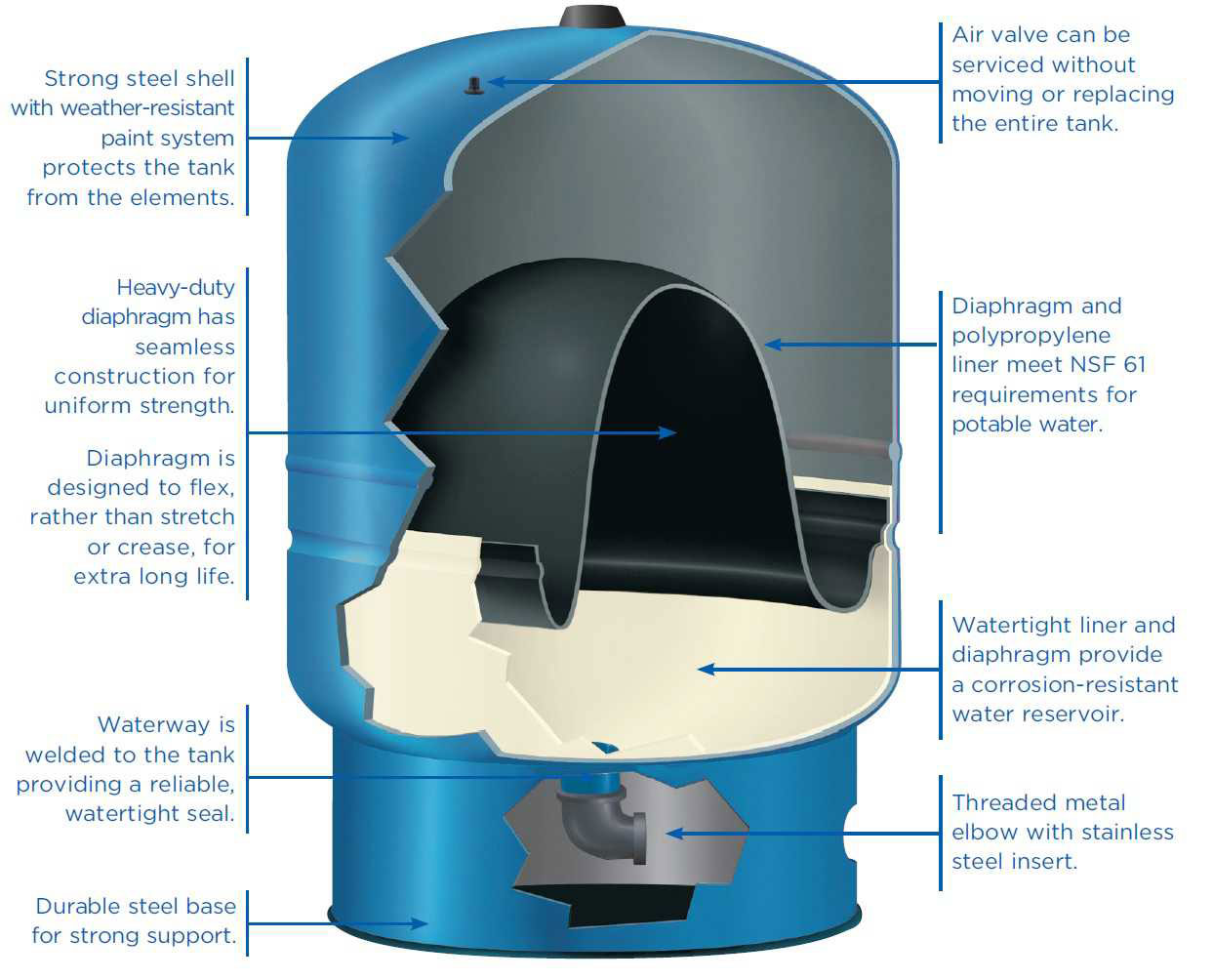
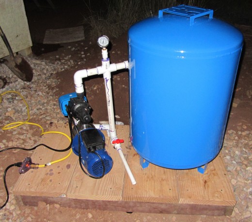
DIY PRESSURE TANK INSTALL howto Plumb diaphram type Tank well Pressure Tank install DIY, A how to install a well pump pressure tank.diy plumbing, cheap, tips, and tricks. Replace a deep well pressure tank installed... PDF Installation Manual DIAPHRAGM WELL TANK - American Water The pump tank has been shipped with a factory precharge as indicated on Table 1. If your pump start-up pressure is different from the factory precharge, adjust the tank pressure with the tank empty to your pump start-up pressure. This can be accomplished by simply bleeding air from valve in the top of the tank with an accurate pressure gauge. › plumbing-riser-diagramPlumbing Riser Diagram | Plumbing Services | New York Engineers Of course, the design of the building water distribution system will determine the layout of the plumbing riser diagram, whether or not waste water, and so in, is included in the diagram. Both the flow rate and the flow pressure are important criteria for water distribution systems and pipe sizes need to be selected in keeping with conditions ... Home Plumbing Diagram - Out of This World Plumbing Ottawa The red lines are the hot water supply after it has left the hot water tank. The black lines are waste pipes (grey water and sewage). The yellow lines are the venting pipes; these enable air and gasses to escape the system. If you are looking for a Stittsville plumber, Ottawa plumber or anywhere in between, we'd be happy to help out!
Plumbing Riser Diagram | Plumbing Services | New York Engineers The point of a plumbing riser diagram is to separate out plumbing systems for potable water, waste water, storm water, sewage, and so on to be able to identify exactly where the different piping is located and what it is attached to in terms of appliances, drains, other building systems, and so on. ... Sometimes water-pressure reducing valves ... Plumbing Vents (The Ultimate Guide) - Hammerpedia The circuit-vented branch drain connects to a drainage stack receiving discharge from fixtures on an above floor (see the above plumbing-vent-diagram and check local code). Interestingly enough, circuit venting has been around since the 1920’s. Dr. Roy Hunter even included circuit venting in the Building Materials and Structures Plumbing ... Water Pressure Tank Install EASY DIY Plumbing - YouTube How to install well water pressure tank DIY Plumb pressure tank installation in 10 minutes. Save money Do It Your Self. Deep well pump sediment ruined your b... Pool Plumbing Diagram & Layout Schematic Examples The primary goal of a plumbing pool diagram is to offer insights into the filtration concept. It doesn't delve into the exact pipe layouts - you can't tell exactly where the pipes or valves are located from a pool plumbing diagram. Filtration Diagram A filtration diagram shows the hydraulic design of a swimming pool.
Water Pump keeps on running - pump can't reach shutoff pressure
› toilet-plumbing-diagramsHow a Toilet Works & Toilet Plumbing Diagrams | HomeTips Sep 28, 2020 · How a Toilet Works – Toilet Plumbing Diagram. One of these devices—called a ballcock—is connected to the water supply and controls delivery of water to the tank. When the tank’s water rapidly drops down into the bowl (upon a flush), the pressure causes the bowl’s waste water to go down the drain.
Pressure Tank Thud at empty | Terry Love Plumbing Advice & Remodel DIY ...
How to Install Two Water Pressure Tanks Together | eHow Connect the two water pressure tanks to the main supply line. Once your water pressure tanks are in their proper position, use T-fittings to connect each tank individually to the main line. Install an isolation valve on each connection. For the outflow of the tank nearest the well line entry, use another T-fitting to both return to the main ...
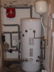
Hot Water Cylinders | Denis Lawson Plumbing & Heating
PDF Well Pump & Pressure Tank Diagram - Clean Water Store 1. Check Valve Located at the top of the pump to prevent back flow into pump and hold the head of water in the system. 2. Torque Arrestor Installed directly above Submersible Pump to protect pump and well components from starting torque damage. 3. Safety Rope A safety line from the top of the well to the pump. 4.
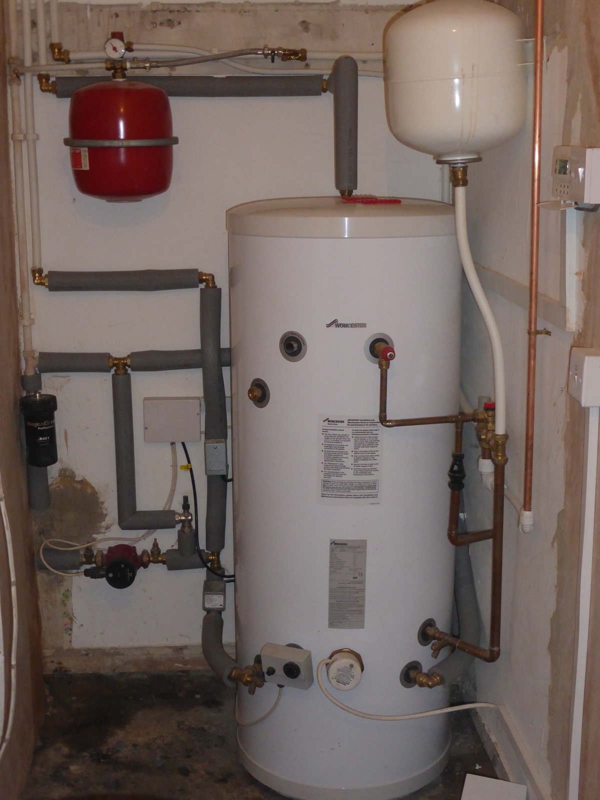
Hot Water Cylinders | Denis Lawson Plumbing & Heating
Well Pump & Pressure Tank Diagram - Well Water Report 1. Check Valve Located at the top of the pump to prevent backflow into the pump and hold the head of water in the system. 2. Torque Arrestor Installed directly above Submersible Pump to protect pump and well components from starting torque damage. 3. Safety Rope A safety line from the top of the well to the pump. 4. Pitless Adapter
Rooftop & Free-Standing Water Tanks, Water Towers & Cisterns, Codes ...
Diagrams --Typical Pump Installations - Water Pump Supply Diagrams --Typical Pump Installations The information provided here is for educational purposes only. Technically qualified personnel should install pumps and motors. We recommend that a licensed contractor install all new systems and replace existing pumps and motors.
Water Pressure Booster Pump | Ernest Electro Engineering
How to Install a Water Heater Expansion Tank in 10 Steps 02/06/2022 · If the water pressure is between 60 and 80 PSI, a 3.2-gallon thermal expansion tank is ideal. An 80-gallon water heater can have a 2-gallon expansion tank if the supply pressure is 40 PSI. Increasing the PSI to 50-60 requires a 3.2-gallon expansion tank. A 4.4-gallon tank is suitable for 80-gallon water heaters with a supply pressure of 80 PSI.

Expansion Tank Diagram | Pearltrees
Toilet Tank Parts: Plumbing Diagram, Pictures, Repairs 05/03/2020 · Since the water pressure in most homes is not sufficient to do this, a toilet tank takes over that role. Tankless toilets have a found a way to work without tanks though. ... Toilet Tank Parts Plumbing Diagram. Parts of a Toilet Tank. Most parts of a toilet tank are universal.

How To Check The Bladder In Your Well Pressure Tank
What is a swimming pool plumbing diagram - Creations … 07/04/2020 · It must be calibrated according to the volume of the pool. Any pressure losses due to the difference in height or the distance between the pool and the pump room must be considered. The filter. The water pushed by the pool pump flows through this tank filled with a filter medium and comes out of it free of all impurities.
0 Response to "38 pressure tank plumbing diagram"
Post a Comment