38 motor control circuit diagram forward reverse pdf
motor control circuit diagram forward reverse pdf motor control circuit diagram forward reverse pdf. Electrical Forward Reverse Motor Starter | Forward and Reverse Control Circuit . 4 years ago Vivek Chaudhary . Forward reverse motor starter circuit के बारे में जानने से पहले यह जान लेना आवश्यक है की forward reverse ... Motor Control Circuits | Ladder Logic | Electronics Textbook When the "Forward" pushbutton is actuated, M 1 will energize, closing the normally-open auxiliary contact in parallel with that switch. When the pushbutton is released, the closed M 1 auxiliary contact will maintain current to the coil of M 1, thus latching the "Forward" circuit in the "on" state.
motor control circuit diagram pdf - PDFprof.com [PDF] AC motor control circuits This worksheet and all related files are. wiring diagram calls ... Forward Reverse DC motor control diagram with timer IC.

Motor control circuit diagram forward reverse pdf
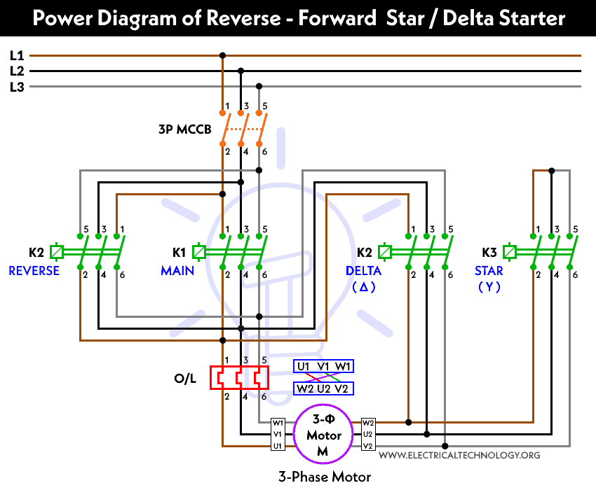
Forward Reverse DC motor control diagram with timer IC - theoryCIRCUIT The diode D1 protects the DC motor from the back emf effect hence there is no output load effect rise. The NPN transistor BD 139 drives the output from timer IC, this output pulse duration decides the speed of DC motor, by varying the VR1 resistor we can vary the pulse output of timer. Datasheet of IC LM555 EX3: Forward/Reverse Motor Operation Connect the circuits as shown in the diagram. b. Switch on the main and sub feeder isolating circuit breakers (Q1, Q2). c. Use the start and stop pushbuttons for motor operation. d. Press the forward direction pushbutton. e. Stop the motor and then press the reverse direction pushbutton to change the rotation of the motor. Three Phase Motor Connection Star/Delta (Y-Δ) Reverse / Forward with ... As we have already shared the Starting method of Three Phase Motor by Star Delta Starter with Timer Circuit (Power and Control Circuits). Now in the below diagrams, Three phase Motor will rotate in two directions viz Forward and Reverse. But We have controlled the direction of rotation of this three phase motor by a Timer circuit. Abbreviations:
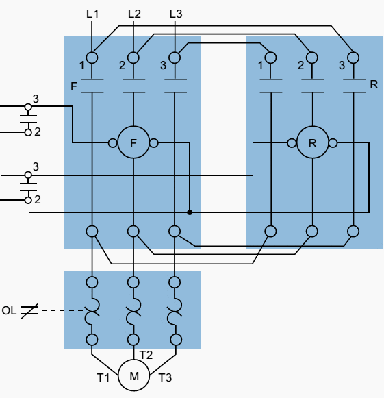
Motor control circuit diagram forward reverse pdf. Forward/Reverse Control Circuits – Basic Motor Control Circuits 36 Forward/Reverse Control Circuits If a three-phase motor is to be driven in only one direction, and upon its initial energization it is found to be rotating opposite to what is desired, all that is needed is to interchange any two of the three line leads feeding the motor. This can be done at the motor starter or at the motor itself. wiring diagram reverse forward diagram reverse forward wiring motor control switch circuit electrical phase power fan plc single speed westinghouse connection mitsubishi schematic industrial. ... ezgo wiring fnr upgrades. Single Phase Motor Forward Reverse Wiring Diagram Pdf - Database faceitsalon.com. phase reversing. Forward Reverse Starter With Timer 3 Phase Motor Wiring ... Star Delta Motor Starter Wiring Diagram Pdf - Naturalium A forward reverse starter with timer for 3 phase motor diagram in the. Star delta starter control circuit wiring diagram consist timer push button for start and stop. The star delta, as the name suggests basically involves feeding Get 19 Wiring Diagram Star Delta Starter Star Delta Forward Reverse Wiring Diagram Pdf Gallery 4K Ace Schematic Diagram Of Forward Reverse Motor Control Forward reverse motor control diagram for three phase motor for a three phase motor forward reverse control circuit. Finally a simple circuit to control the direction of a dc motor. Dol forward reverse motor control circuit. It reveals the components of the circuit as simplified forms as well as the power as well as signal links in between the ...
single phase motor reverse wiring diagrams Forward Reverse Single Phase Motor Wiring Diagram - Wiring Diagram facybulka.me. reverse reversing lafert capacitor jeanjaures37 tukune. Forward Reverse Three Phase Motor Wiring Diagram Electrical Info PICS . motor diagram electrical wiring forward reverse phase engineering generator diy. Wiring Diagram: Chapter 1.2. PDF Electrical Drive Systems 324 According to the IEC convention, schematic diagrams are divided into: main circuit, i.e. the three-phase circuit control circuit, usually 24V DC or 24/110/230/400V 1˚ AC +N.B.Remember the main and... Electrical Drive Systems 324 - Industrial Motor Control Forward/Reverse Control of Three-phase Induction. Motors. Plugging of Three-phase Induction ... schematic diagrams, these will be used in this course. Motor Control Circuits | Motor Control Wiring Diagrams | Motor Logic When the "Forward" pushbutton is actuated, M 1 will energize, closing the normally-open auxiliary contact in parallel with that switch. When the pushbutton is released, the closed M 1 auxiliary contact will maintain current to the coil of M 1, thus latching the "Forward" circuit in the "on" state.
simple circuit motor forward reverse control diagram datasheet ... simple circuit motor forward reverse control diagram datasheet, cross reference, circuit and application notes in pdf format. star delta forward reverse wiring diagram Star Delta Forward Reverse Wiring Diagram Pdf / 3 Phase Star Delta anorexiceatingboys.blogspot.com. wiring starter. Star Delta Reverse And Forward Motor Control Circuit In Urdu English . star delta reverse circuit forward control diagram motor urdu english. How To Change The Rotation Direction And Wire Configuration - Star Or PDF Basic Motor Control - opentextbc.ca Motor Starters and Contactors 11. Overview 37 12. Overload Relays 39 13. Manual Motor Starters 43 14. Magnetic-Motor Starters 45 15. Forward/Reverse Starters 49 16. Control Relays 51 17. Timers 53 18. Self Test 3 57 Part IV. Diagrams 19. Schematic vs. Wiring Diagrams 61 Accessibility Statement Accessibility Statement PDF Basic Wiring for Motor Contol - Eaton The control circuit is separate from the motor circuit. The control circuit may not be at the same voltage as the power circuit. When the voltage of the control and power circuits is the same, it is referred to as Common Control. If the volt-ages are different, it is called Separate Control. Figure 4. Typical Starter Wiring Diagram — Three-Phase
Motor Control Circuit Diagram Forward Reverse With Timer - Blogger In the forward reverse timer diagram all main and control wiring shown. Wiring diagram for a forward and reversing motor starter datasheet, cross reference, circuit and application notes in pdf format. In a schematic diagram, mechanical interlocks are shown as dashed lines from each coil joining at a .
PDF Motor Control Handbook - NHP Direct on line starters and reversing startersrequired to activate the contactor coil, it is also easy 30 5.1 Several command locations to integrate into an automatic control system where 30 5.2 Direct on line starters (Contactor with overload relay) 32 5.3 Direct on line starters with mechanical latch 36 5.4 Reversing starters 40 6.
PDF AC motor control circuits - ibiblio The circuit shown here provides two-direction control (forward and reverse) for a three-phase electric motor: L1 L2 M1 To 3-phase motor power source M1 OL Forward OL Reverse M2 M2 M1 M2 Explain how the reversal of motor direction is accomplished with two different motor starters, M1 and M2.
PDF Forward Reverse Motor Power Control Circuit Diagram Pdf Free Forward Reverse Motor Power Control Circuit Diagram Pdf Free [PDF] Forward Reverse Motor Power Control Circuit Diagram PDF Book is the book you are looking for, by download PDF Forward Reverse Motor Power Control Circuit Diagram book you are also motivated to search from other sources Low Density Polyethylene (LDPE) DIAGRA Process Overview ...
wiring diagram motor forward reverse Electrical Wiring Diagram Forward Reverse Motor Control And Power ... Single Phase Motor Control Circuit Diagram Forward Reverse Pdf webmotor.org. reversing. 46 Forward And Reverse Motor Connection - Wiring Diagram Source Online apiccolisogni.blogspot.com. reversing attend. Wiring Up Forward Reverse Motor Starter With Electric Interlock
PDF Motor control circuits - IDC-Online "Reverse" pushbutton is pressed. These parallel auxiliary contacts are sometimes referred to as seal-in contacts, the word "seal" meaning essentially the same thing as the word latch. However, this creates a new problem: how to stop the motor! As the circuit exists right now, the motor will run either forward or backward once the corresponding
motor control circuit diagram forward reverse pdf - Inst Tools motor control circuit diagram forward reverse pdf Motor Control Circuit Wiring A simple three-phase, 480 volt AC motor-control circuit is shown here, both in pictorial and schematic form. This entire assembly Motor Control Circuits
PLC Implementation Of Forward/Reverse Motor Circuit With Interlocking Figure 2 - Forward/reverse motor wiring diagram. For simplicity, the PLC implementation of the circuit in Figure 1 includes all of the elements in the hardwired diagram, even though the additional starter contacts (normally closed R and F in the hardwired circuit) are not required, since the push button interlocking accomplishes the same task.
REV / FOR Three-Phase Motor Connection Power and Control diagrams Three Phase Motor Connection Reverse and Forward Power and Control wiring diagrams(Two Direction one speed) Abbreviations: O/L = Over Load Relay. NO = Normally Open. NC = Normally Close. REV = Reverse. FOR = Forward.
PDF Wiring Diagrams Forward Reverse Motor Single Phase Wiring Diagrams Forward Reverse Motor Single Phase ... Diagram Book Switch Relay. How to wire an RCBO wiring diagrams electrical photos. Three Phase Motor Power amp Control Wiring Diagrams. Lessons In Electric Circuits Volume II AC ... Motor Drive VFD VE Series Controller pdf manual download Square D Wiring Diagram Book Switch Relay May 10th ...
MOTOR CIRCUITS AND CONTROL - Applied Industrial Electricity As the circuit exists right now, the motor will run either forward or backward once the corresponding pushbutton switch is pressed and will continue to run as long as there is power. To stop either circuit (forward or backward), we require some means for the operator to interrupt power to the motor contactors. We'll call this new switch, Stop:
Three Phase Motor Connection Star/Delta (Y-Δ) Reverse / Forward with ... As we have already shared the Starting method of Three Phase Motor by Star Delta Starter with Timer Circuit (Power and Control Circuits). Now in the below diagrams, Three phase Motor will rotate in two directions viz Forward and Reverse. But We have controlled the direction of rotation of this three phase motor by a Timer circuit. Abbreviations:
EX3: Forward/Reverse Motor Operation Connect the circuits as shown in the diagram. b. Switch on the main and sub feeder isolating circuit breakers (Q1, Q2). c. Use the start and stop pushbuttons for motor operation. d. Press the forward direction pushbutton. e. Stop the motor and then press the reverse direction pushbutton to change the rotation of the motor.
Forward Reverse DC motor control diagram with timer IC - theoryCIRCUIT The diode D1 protects the DC motor from the back emf effect hence there is no output load effect rise. The NPN transistor BD 139 drives the output from timer IC, this output pulse duration decides the speed of DC motor, by varying the VR1 resistor we can vary the pulse output of timer. Datasheet of IC LM555


![[DIAGRAM] Star Delta Timer Wiring Diagram FULL Version HD Quality ...](https://www.factomart.com.sg/wp-content/uploads/2017/10/Pasted-image-at-2017_10_05-11_02-AM.png)


0 Response to "38 motor control circuit diagram forward reverse pdf"
Post a Comment