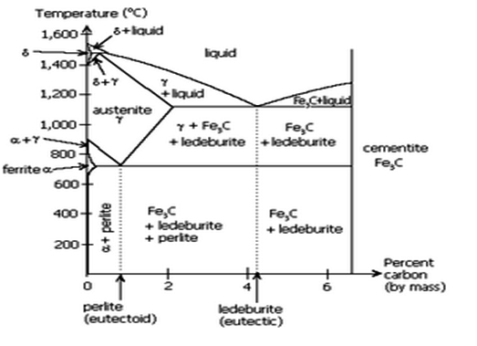
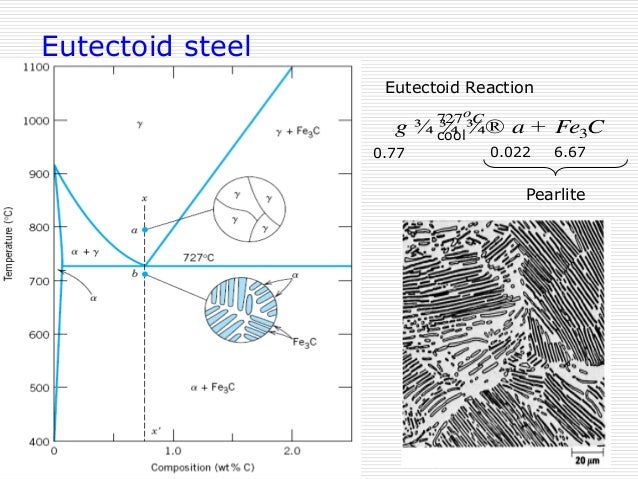
38 iron iron carbide diagram
Iron carbon equilibrium diagram with explanation. ||Engineer ... - YouTube Iron Carbide Equilibrium Diagram/ Material Science / Engineer's AcademyHello Everyone Welcome To AIM AMIEIn this videos we have covered the Iron Carbon Equil... What is the Iron-Carbon Phase Diagram? - Engineering Choice What is the significance of a0 temperature in iron iron carbide diagram? The A1 line is the eutectoid-temperature line and is the lowest temperature at which f.c.c. iron can exist under equilibrium conditions. Just above A1 line, the microstructure consists of approximately 25 percent austenite and 75 percent ferrite.
ch9-iron-carbide_phase_diagramselmas.pdf - THE IRON- CARBON SYSTEM ... THE IRON-IRON CARBIDE (Fe-Fe 3 C) PHASE DIAGRAM Iron-Iron Carbide (Fe-Fe 3 C ) phase diagram is a portion of the iron-carbon (Fe-C) phase diagram. The composition axis in figure extends only to 6.7 wt.% C; at this concentration the iron carbide or cementite (Fe 3 C) is formed which is represented by a vertical line on the phase diagram. The Iron-carbon system may be divided into two parts: an ...
Iron iron carbide diagram
PDF Iron-Iron carbide (Fe-Fe C) Phase Equilibrium Diagram The diagram shows the phases present at various temperatures for very slowly cooled Fe-C alloys with carbon content up to 6.67%. Information given by the diagram: ... Cementite or Iron carbide: It is an intermetallic iron-carbon compound. Carbon in excess of solubility limit forms a separate phase called iron carbide (Fe 3 Iron-Iron Carbide Phase Diagram | Material Engineering The Iron-Iron carbide (Fe-Fe 3 C) is defined by five individual phases and four invariant reactions. Five phases are- α-ferrite (BCC) Fe-C solid solution, γ-austenite (FCC) Fe-C solid solution, δ -ferrite (BCC) Fe-C solid solution, Fe 3 C (iron carbide) or cementite - an inter- metallic compound and liquid Fe-C solution. Four invariant reactions are eutectoid, eutectic, monotectic and ... PPT - The Iron-Iron Carbide Phase Diagram PowerPoint Presentation, free ... The Iron-Iron Carbide Phase Diagram. Heat Treatment of Steel. Features. Phases present. L. a ferrite Bcc structure Ferromagnetic Fairly ductile. d Bcc structure Paramagnetic. g austenite Fcc structure Non-magnetic ductile. Fe 3 C cementite Orthorhombic Hard brittle. Reactions. Uploaded on Apr 12, 2013. Samuel.
Iron iron carbide diagram. Iron-Carbon Equilibrium Diagram | Metallurgy Iron-Cementite diagram is not a true equilibrium diagram, since equilibrium means no change of phase with time, however long it may be. Graphite is more stable form of carbon. ... Iron Carbide, Fe 3 C: It is an interstitial intermediate compound having a fixed carbon content of 6.67%. It has a complex orthorhombic crystal structure with 12 iron ... IRON CARBIDE EQUILIBRIUM DIAGRAM - Marine Inbox September 30, 2019. 0. 1928. The part of iron and carbon alloy system line diagram representation of unalloyed iron and an interstitial compound, iron carbide (Fe3C), containing 6.67 percent carbon by weight is called iron-iron carbide equilibrium diagram. It should be noted that though it is called as equilibrium diagram, it is not a true ... Iron-Carbon Diagram Explanation [PDF] - Mechanical E-Notes Iron-Carbon Phase Diagram with Detailed Explanation: If the percentage of the carbon is in the range of 0 to 2.11 % then it is called Steel and if the percentage of carbon is in the range of 2.11 to 6.67% then it is called Cast iron. As the carbon content increases, it produces more Iron-Carbide volume and that phase will exhibit high hardness. Iron-Carbon Phase Diagram Explained [with Graphs] - Fractory The weight percentage scale on the X-axis of the iron carbon phase diagram goes from 0% up to 6.67% Carbon. Up to a maximum carbon content of 0.008% weight of Carbon, the metal is simply called iron or pure iron. It exists in the α-ferrite form at room temperature. From 0.008% up to 2.14% carbon content, the iron carbon alloy is called steel.
Iron iron-carbide phase diagram - SlideShare THE IRON-IRON CARBIDE DIAGRAM A map of the temperature at which different phase changes occur on very slow heating and cooling in relation to Carbon, is called Iron- Carbon Diagram. Iron- Carbon diagram shows the type of alloys formed under very slow cooling, proper heat-treatment temperature and how the properties of steels and cast irons can ... PDF Iron-Iron Carbide Diagram Lab - Homework For You 2. Using the Iron-Iron Carbide Phase Diagram provided, place a line for the assigned steel or cast iron on the diagram. 3. Write a technical report on the Iron-Iron Carbide Phase diagram. The report should contain two sections. • The first section, labeled General, should describe the diagram as a whole, its purpose and its primary IRON - Iron carbide diagram - YouTube The Iron-Iron Carbide Equilibrium Diagram - Marine Engineering The part of iron-carbon alloy system diagram between pure iron and an interstitial compound, iron carbide (Fe 3 C), containing 6.67 percent carbon by weight is called iron-iron carbide equilibrium diagram. It may be noted that though it is called as equilibrium diagram, it is not a true equilibrium diagram, since equilibrium implies no change ...
Iron-Iron Carbide Phase Diagram Example The diagram shows iron and carbons combined to form Fe-Fe 3 C at the 6.67%C end of the diagram. The left side of the diagram is pure iron combined with carbon, resulting in steel alloys. ... Calculate the number of grams of carbide that form per 100g of steel. 4. Determine the amount of pearlite in a 99.5% Fe-0.5%C alloy that is cooled slowly ... Iron-Carbon Diagram, Transformation in steel, Transformation in ... The part of iron-carbon phase diagram plotted for the concentrations (weight percent) upto 6.67% carbon is of commercial significance. This part between pure non and iron carbide (Fe 3 C) is called as iron-iron carbide diagram. This is not a true equilibrium diagram because the compound iron carbide does not form a true equilibrium phase. The Iron-Iron Carbide Equilibrium Diagram - Practical Maintenance The Iron-Iron Carbide Diagram. The part of iron-carbon alloy system diagram between pure iron and an interstitial compound, iron carbide (Fe 3 C), containing 6.67 percent carbon by weight is called iron-iron carbide equilibrium diagram. It may be noted that though it is called as equilibrium diagram, it is not a true equilibrium diagram, since ... Iron Carbon Equilibrium Diagram with Explanation [Phase Diagram] The Iron carbon equilibrium diagram (also called the iron carbon phase diagram) is a graphic representation of the respective microstructure states of the alloy iron - carbon (Fe-C) depending on temperature and carbon content. The iron carbon phase diagram is commonly used to fully understand the various phases of steel and cast iron.
CH 6 - Iron-Iron Carbide Diagram: Cast Iron Flashcards | Quizlet Start studying CH 6 - Iron-Iron Carbide Diagram: Cast Iron. Learn vocabulary, terms, and more with flashcards, games, and other study tools.
Iron Carbon Phase or Equilibrium Diagram or Iron Carbide Diagram Iron carbide equilibrium diagram shows us metastable conditions, one can achieve equilibrium changes under slow heating and cooling. Importance of Iron Carbon Equilibrium Diagram. According to the requirements of different applications, we can develop new alloys by handing them at different temperatures and changing the compositions of carbon ...
PDF The iron-iron carbide (Fe-Fe3C) phase diagram The iron-iron carbide (Fe-Fe 3C) phase diagram Ferrite-α-BCC, low C solubility(0.022%wt), magnetic Austenite-γ-FCC, high C solubility(2.14%wt), nonmagnetic Ferrite-δ-BCC ... the amount of carbide (cementite) in grams that forms per 100 g of steel c) the amount of pearlite and proeutectoid ferrite (α) 5 Phase Equilibria Solution: 94.3 g


0 Response to "38 iron iron carbide diagram"
Post a Comment