45 well pump system diagram
PDF CHAPTER II REFERENCE DRAWINGS for WET/DRY WELL AND SUBMERSIBLE PUMPING ... 100. Bubbler System Control Diagram (With Electric Pressure Switches) Wet/Dry Well ....PS-E2-1B 101. Float System Control Diagram (Wet/Dry Well) .....PS-E2-2 102. Pump One Control Diagram (Wet/Dry Well) .....PS-E2-3A 103. Diagnosing Pump and Well Problems - Plumber Magazine This usually comes from two sources: a malfunctioning pump, or a break or crack in the water pipe above the pump. To confidently diagnose and fix these problems, the well has to be pulled. Cloudy or muddy water. This sign indicates a sinking water table and a pump that's pulling from shallow water where the percentage of silt and sand is higher.
Water Well Pumps and Systems - How a Water Well Pump Works Jet pumps are mounted above the well, either in the home or in a well house, and draw the water up from the well through suction (see Single-Drop Jet-Pump System diagram on next page). Because...

Well pump system diagram
Photo Guide to Well Water Pump Controls & Switches - private well pump ... Carson, Dunlop & Associates Ltd., 120 Carlton Street Suite 407, Toronto ON M5A 4K2. Tel: (416) 964-9415 1-800-268-7070 Email: info@carsondunlop.com.The firm provides professional HOME INSPECTION SERVICES and also extensive HOME INSPECTION EDUCATION and home inspection-related PUBLICATIONS.Alan Carson is a past president of ASHI, the American Society of Home Inspectors. pump simple schematic diagram pump simple schematic diagram. Simple automatic plant watering circuit. Water filter iron well treatment diagram tank system carbon pressure filtration systems manganese purification treat oxide filters cost clean chlorinator. 1964 mustang wiring diagrams. pump simple schematic diagram. Husqvarna P-ZT48 CA - 966663802-02 (2016-11) Parts Diagram ... Well System Components - Wellowner.org Well screens are filtering devices used to prevent excess sediment from entering the well. They attach to the bottom of the casing or in intercepted water-bearing zones, allowing water to move through the well, while keeping out most gravel and sand. The most popular screens are continuous slot, slotted pipe, and perforated pipe.
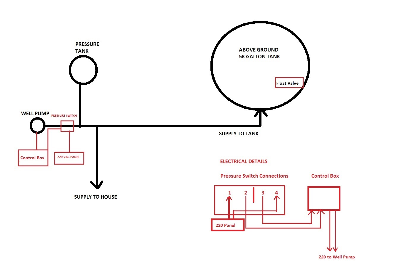
Well pump system diagram. How Home Well Water Pump and Pressure Systems Work The pressure tank in your well system creates water pressure by using compressed air. Because of this pressure, when a valve or faucet is opened in your home the water is pushed out of the tank through the pipes in your home. When the water in the pressure tank drops below a preset level, a pressure switch is activated which turns on the pump. Submersible Well Pump Accessories Installation Diagram Submersible Well Pump Accessories Installation Diagram This illustration is for educational purposes It is not intended as an installation guide. Check local codes for requirements and restrictions. Technically qualified personnel must install this equipment. Questions & Answers How a Well Pressure Tank Works - with Diagrams - Plumbing Sniper Water Pressure Tank Installation Diagram The image below shows the typical installation diagram of a well pressure tank, as well as other components of a well system. Image: Lakeland Water Pump How a Bladder Pressure Tank Works A bladder pressure tank is a steel tank with a bladder inside which looks like a balloon. Water Well Diagram and Proper Well Construction Here are some of the more important elements included in the water well diagram above. Borehole - The borehole should be about 50mm (2 inches) wider all around than the well casing. The borehole needs to be clear of obstructions all the way down, and should be deep enough to reach the lowest expected water level.
PDF Well Diagram - NJGWA This list and the illustration on the front page are not intended as an installation guide. Check local codes for actual requirements and restrictions. CHECK VALVE (Section G) Located at the top of the pump, it prevents backflow into the pump and holds the head of water in the system. BRASS ROPE ADAPTER Diagrams --Typical Pump Installations Diagrams --Typical Pump Installations The information provided here is for educational purposes only. Technically qualified personnel should install pumps and motors. We recommend that a licensed contractor install all new systems and replace existing pumps and motors. What Is a Well Pump Control Box and How Does It Work? A well pump control box is basically the brain of a water system because it handles many tasks to keep the system functioning properly. Pump control boxes are responsible for monitoring the flow of water and controlling a water pump to keep it at the desired level. Pump control can vary depending on the type of control box that is installed. Submersible Well Pump Wiring Diagrams | LoveToKnow The diagrams for both the two and three wire pumps can be downloaded using Adobe. To replace the two wire pump: After determining the voltage is zero, disconnect the motor wires directly from the pressure switch box, M1 and M2. The green ground wire should also be terminated to the box and a ground coming from the panel.
Well Diagram - Water Systems Council Well Diagram This illustration is intended to represent some of the components that can be included in a water well system and is not intended as an installation guide. Check local or state codes for actual requirements and restrictions. Sample Water Well System Move your mouse over a number to view the description Deep Well Pump Installation Diagram - Pinterest Deepwell cargo pumps are electrically driven cargo discharge pumps which are now used in place of Cargo Operated Pump Turbine (COPT) on tanker ships. . Learn about the different parts of the pump in this infographics. P. Paul Ong. Oil & Gas. Well Water System. Water Pump System. Water Filtration System. Water Systems. Anatomy Of A Water Well | Parts Of A Well - C&J Well Co. At the top of a water well is the wellhead. Of all the water well components, this is the most visible. The head is durable PVC and holds a cap that keeps debris out of the well. A smaller PVC pipe attached to the head protects the electrical wires that power the well pump. Anatomy of a Well: Casing Understanding your well system components - Northeast Water Wells Should be used on any system where the pump could develop greater pressure than the maximum rating of the system. 18.) Pressure Gauge - Measures water pressure in Pressure Tank. 19.) Pressure Switch - Signals the pump to start when the water system drops to a preset low pressure, and to stop when the high pressure mark is reached. 20.)

Engineering of Water Systems - Water Well Journal
PDF Well Pump & Pressure Tank Diagram - Clean Water Store 1. Check Valve Located at the top of the pump to prevent back flow into pump and hold the head of water in the system. 2. Torque Arrestor Installed directly above Submersible Pump to protect pump and well components from starting torque damage. 3. Safety Rope A safety line from the top of the well to the pump. 4.

Components Of A Typical Well Water System - YouTube
Deep Well Jet Pump Diagram:How It Works - Lambda Geeks In the section below we shall study about the working of a deep well jet pump. In a deep well pump, the pipe which is connected to the impeller casing draws water inside the jet's body that is located around 10-20 ft deep below the minimum well water level. A second pipe connects to the output of the pump.
32 Above Ground Well Pump Diagram - Wiring Diagram Database
How Does a Well Pump Work: Well Water Basics The well pump, or water pump, is the heart of the system. It is what pumps water upward and into the household or designated water system. The two most popular types of pumps used today are jet pumps and submersible pumps. Both pumps rely on centrifugal force in order to force water upward.

Stainless steel submersible pump installation diagram.jpg | Submersible ...
How a Well Water System Works [Explained with Diagram] The Well Pump - It is also known as a water pump, and it is the most important component of a well system. It is responsible for pumping out water from the well. You can either use above ground or submersible water pumps for this purpose. The amount of water needed and the type of well determines which pump is best for you.
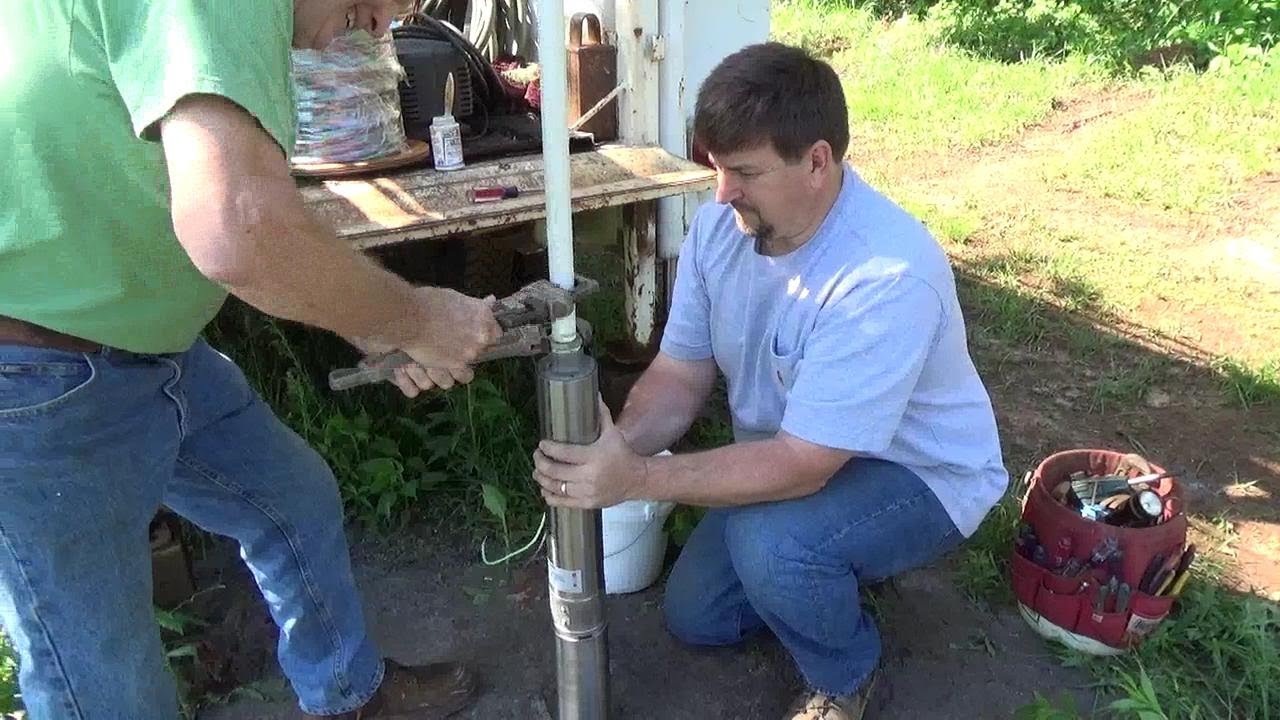
How to install a Submersible Pump - YouTube
How to Install and Wire a Well Pump - Water Pumps Direct Two-Wire Well Pump Wiring Diagrams 2-wire well pump diagrams are slightly easier to understand, and are more straight-forward to wire. Black wires go to black wires, and the green wire (the ground) goes to the ground wire. Fig. 1 (Above): 2 Wire Well Pump Wiring Diagram Three-Wire Well Pump Wiring Diagrams

Well pump troubleshooting - DoItYourself.com Community Forums
Components Of A Typical Well Water System - YouTube An overview and description of typical residential well water system components. Pressure switch, well tank and other components explained.

10 best images about Well Pump House on Pinterest | Water well, A well ...
PDF TYPICAL SHALLOW WELL JET PUMP INSTALLATION - Grover Electric TYPICAL SHALLOW WELL JET PUMP INSTALLATION 1. Shallow well jet systems can be used when the depth of the water is no more than 20'. Water depths of more than 20' but less than 80' deep would use a deep well jet system or submersible pump. A submersible pump can also be used in shallow wells. 2. We recommend a captive air pump tank.

Aerobic System Control Panels, Aerobic System Control Box, Septic ...
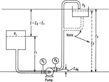
HOW TO design a pump system The system in Figure 3 is another typical domestic water supply system that takes it's water from a deep well (200-300 feet) and uses a multi-stage submersible pump often called a turbine pump. Figure 3 Figure 3a source: The Ground Water Atlas of Colorado Figure 3b Figure 3c Typical deep well submersible pump Pressure, friction and flow Figure 4

Smart Irrigation System Using Android App and IoT – MD Jahid Hasan
Deep well pump installation, Design and piping diagram layout deep well pump installationdeep well pump installation diagramdeep well pump installation instructionsdeep well pumpdeep well drillingdeep well water pumpdee...
Pump Calculations | Engineering360
Well System Components - Wellowner.org Well screens are filtering devices used to prevent excess sediment from entering the well. They attach to the bottom of the casing or in intercepted water-bearing zones, allowing water to move through the well, while keeping out most gravel and sand. The most popular screens are continuous slot, slotted pipe, and perforated pipe.
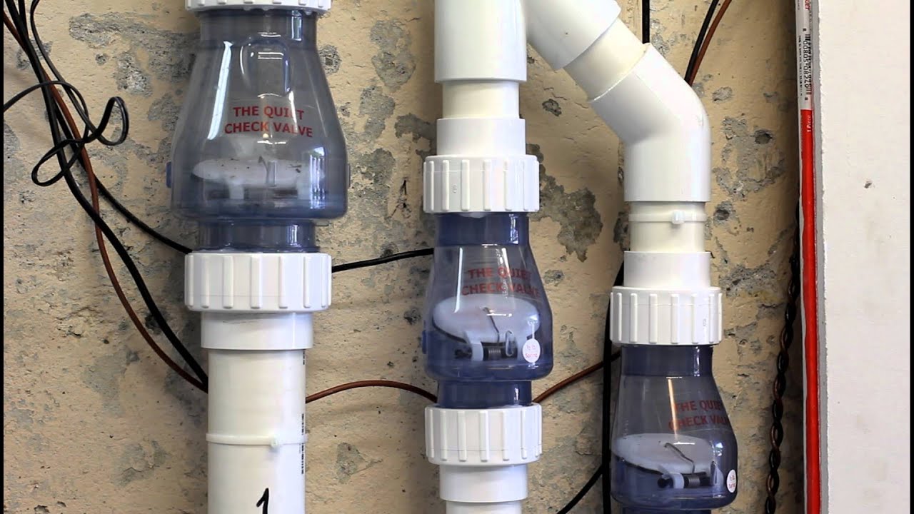
Sump Pump Check Valve test - YouTube
pump simple schematic diagram pump simple schematic diagram. Simple automatic plant watering circuit. Water filter iron well treatment diagram tank system carbon pressure filtration systems manganese purification treat oxide filters cost clean chlorinator. 1964 mustang wiring diagrams. pump simple schematic diagram. Husqvarna P-ZT48 CA - 966663802-02 (2016-11) Parts Diagram ...

Ask These Questions—to Get the Right Process Pump - IBT Industrial ...
Photo Guide to Well Water Pump Controls & Switches - private well pump ... Carson, Dunlop & Associates Ltd., 120 Carlton Street Suite 407, Toronto ON M5A 4K2. Tel: (416) 964-9415 1-800-268-7070 Email: info@carsondunlop.com.The firm provides professional HOME INSPECTION SERVICES and also extensive HOME INSPECTION EDUCATION and home inspection-related PUBLICATIONS.Alan Carson is a past president of ASHI, the American Society of Home Inspectors.
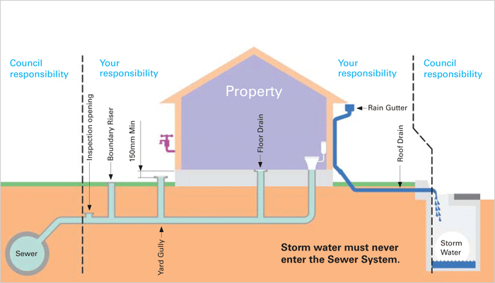
Sewers - Wagga City Council

Engineering of Water Systems – Water Well Journal

Different flowing systems resulting from various pump placement in the ...
0 Response to "45 well pump system diagram"
Post a Comment