43 white rodgers zone valve wiring diagram
White Rodgers Zone Valves - SupplyHouse.com These White Rodgers Zone Valves are designed for hydronic heating systems. Zone valves control the flow of water to a specific zone in a hydronic heating system. ... 1361-103 1" Sweat Zone Valve (Two Wire) SKU: 1361-103 White Rodgers. SKU: 1361-103. Brand: White Rodgers (79)-+ $173.40 each ADD TO CART. Add to List. List. 108. Tue, Jul 26 TYPE 13A01 & 13A03 WHITE-RODGERS 2-WIRE, 2-WAY For use on … TYPE 13A01 & 13A03 WHITE-RODGERS 2-WIRE, 2-WAY For use on systems up to 150 Psi INSTALLATION INSTRUCTIONS WHITE-RODGERS DIVISION EMERSON ELECTRIC CO. 9797 REAVIS RD., ST. LOUIS, MO. 63123 (314) 577-1300, Fax (314) 577-1517 9999 HWY. 48, MARKHAM, ONT. L3P 3J3 (905) 475-4653, FAX (905) 475-4625 WHITE-RODGERS Printed …
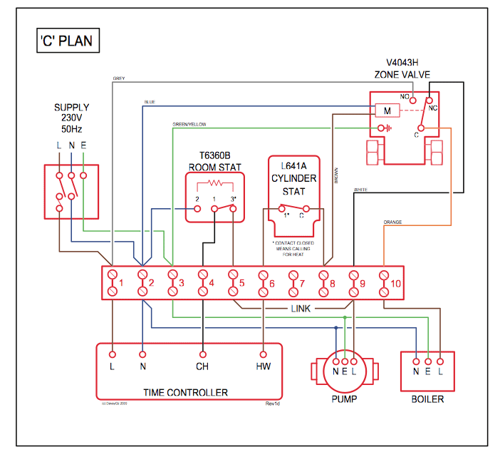
Wiring Diagram For White Rodgers Zone Valve As the.Mar 19, · I have an old boiler,three zone system with 3 White-Rodgers zone-a-flow water schematron.org the wiring has been pulled off the valve controlers,2 zones have had the thermostats removed and 1 has been replaced and is wired to work the boiler with 2 schematron.org the W-R valves have been opened by schematron.org you know the entire …
White rodgers zone valve wiring diagram
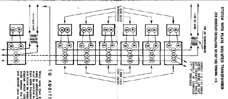
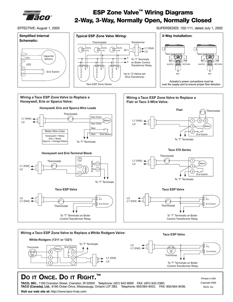
PDF TYPE 1311 - SupplyHouse.com If the boiler manufacturer recommends a wiring diagram, follow his instructions. If none are available, the following diagrams show suggested circuits for Type 1311 Water Valves in conjunc- tion with other W-R controls. A 40 VA transformer will handle up to four (4) water valves. A 20 VA transformer will handle up to two (2) water valves. Zone Valve Wiring Manuals Installation & Instructions: … The Load wire is taken to Terminal #1 on the White Rogers zone valve so that when it makes aux switch #2 there is no voltage across the switch, and the load is taken TO the thermostats directly for the Honeywell zone valves, and The … White Rodgers Zone Valve Wiring - diagramweb.net 09.06.2018 · White Rodgers Zone Valve Wiring White Rodgers Zone Valve Wiring White Rodgers - 3/4" Sweat Zone Valve (Three Wire) - 3/4" Zone Valve (Three Wire) Features 15 PSI Maximum Differential Across Valve Degrees. …
White rodgers zone valve wiring diagram. Looking wiring diagram white rogers zone valve - JustAnswer HVAC Supervisor. 37,083 satisfied customers. I've got a W-R F19-0097 zone valve 2 red, 2 and 2 wires, I've got a W-R F19-0097 zone valve 2 red, 2 white and 2 green wires, need to disconnect the end switch because the valve is keeping the boiler … read more. White Rodgers Zone Valves - YouTube A zone valve is used to control the flow of water or steam in a hydronic heating system. You want to use zone valves in heating systems where you will be hea... white rodgers thermostats manual White Rodgers Thermostat pt.slideshare.net. White Rodgers NP100 Electronic Single Stage Non-Programmable Thermostat . thermostat rodgers np100 np110 thermostats. Wiring zone honeywell valve diagram taco valves heating motorised installation air wire diagrams guide instructions handler schematic rodgers heat heater. White ... taco wiring diagram White Rodgers Zone Valve Wiring Schematic - Wiring Diagram wiringdiagram.2bitboer.com. 1311. Taco Sr504-4 Wiring Diagram diagramweb.net. ... taco zone valve wiring diagram 571 valves common pull schematic wifi tstat wire system regarding doityourself thermostatic controls transformer. Testing, Wiring, Taco Sentry Zone Valve! ...
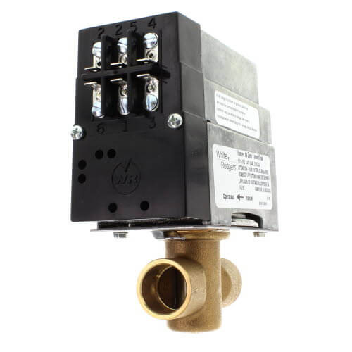
White Rodgers Zone Valve Wiring Diagram Database Print the wiring diagram off and use highlighters to be able to trace the circuit. When you use your finger or stick to the circuit together with your eyes, it’s easy to mistrace the circuit. PDF RESIDENTIAL ZONE VALVES WIRING - SupplyHouse.com ) Attach a voltmeter to terminals and 2. Power (24 volts) should always be present on and 2. If power is interrupted check transformer or power source. 2) With a voltmeter attached as above, jumper terminals 5 and 4 to verify the valve opens. If power is present on 1 and 2 but the valve fails to open check connections. White Rodgers Zone Valve Wiring Diagram - Magazine Order Now White Rodgers Zone Valve Wiring Diagram - If you have a White-Rodgers heat pump and thermostat system or an Emerson thermostat the wiring likely follows a particular pattern. It makes the process of assembling circuit easier. 1300 Series valves for zoning systems up to 50 PSI operate quietly and efficiently providing years of reliable service ... Wire diagram White Rodgers Zone A Flow Water Valve 1361-103 The 30 year old zone valve that I have is marked: White Rodgers Zone A Flow Water valve Type 1361-103 1in 0.2amp 25v ac The new and old valves look very similar but the new valve has 5 screw terminals marked 1 thru 5.. The old valve has 5 wire inserts marked 1 thru 4. I'll try to send a diagram. My system is a bit unusual in that it isn't really used as a zone valve (I have only one zone).
White Rodgers 3 wire zone valve wiring question - DIY Home Improvement ... I previously had (2) 3 wire, white Rodgers zone valves hooked up with no zone controller. I have (2) 2 wire thermostats. Here is the wiring diagram for the wr zone valves Rodgers - 1311-102 - Install Instructions.pdf 1361 102 White Rodgers Zone Valve Wiring Diagram 01.11.2019 · SCHEMATIC OF VALVE Two Wire Zone Valve TROUBLESHOOTING:) Attach a voltmeter to terminals and 2. Power (24 volts) should always be present on and 2. If power is interrupted check WIRING … White Rodgers Gas Valve Wiring Diagram Variety of white rodgers gas valve wiring diagram. A wiring diagram is a streamlined conventional pictorial depiction of an electrical circuit. It shows the elements of the circuit as simplified shapes, and the power and signal links in between the tools. White Rodgers Zone Valve Wiring - diagramweb.net White Rodgers Zone Valve Wiring White Rodgers - 3/4" Sweat Zone Valve (Three Wire) - 3/4" Zone Valve (Three Wire) Features 15 PSI Maximum Differential Across Valve Degrees. The White Rogers zone valves have three wires, white red and green. Is the wiring straight forward at the new thermostat end? Thanks Nick.
White Rodgers Zone Valve Wiring Diagram
White Rodgers 3 Wire Zone Valve Wiring Diagram - alejandrarori 22.08.2021 · White Rodgers 3 Wire Zone Valve Wiring Diagram. When zone 3 is switched to the priority setting and is The Load wire is taken to Terminal 1 on the White Rogers zone valve so that. Honeywell zone valve wiring diagram. CLASS 1 WIRING Fig. The schematic shows the valve in the closed position. It makes the process of assembling circuit easier.
White Rodgers Zone Valve Wiring Schematic - Wiring Diagram
White Rodgers 1361-103, 1361-104, 1361-102 Installation Instructions WHITE-RODGERS. HYDRONIC ZONE VALVES (2 WIRE) ... Make connections to screw terminals according to wiring diagram. NOTE: To check motor operation without thermostat connected, jumper 2 and 4 to open valve; remove jumper to close valve. If the boiler manufacturer recommends a wiring diagram, follow his instructions. If none are available, the ...

White Rodgers Zone Valve Wiring Diagram | Free Wiring Diagram
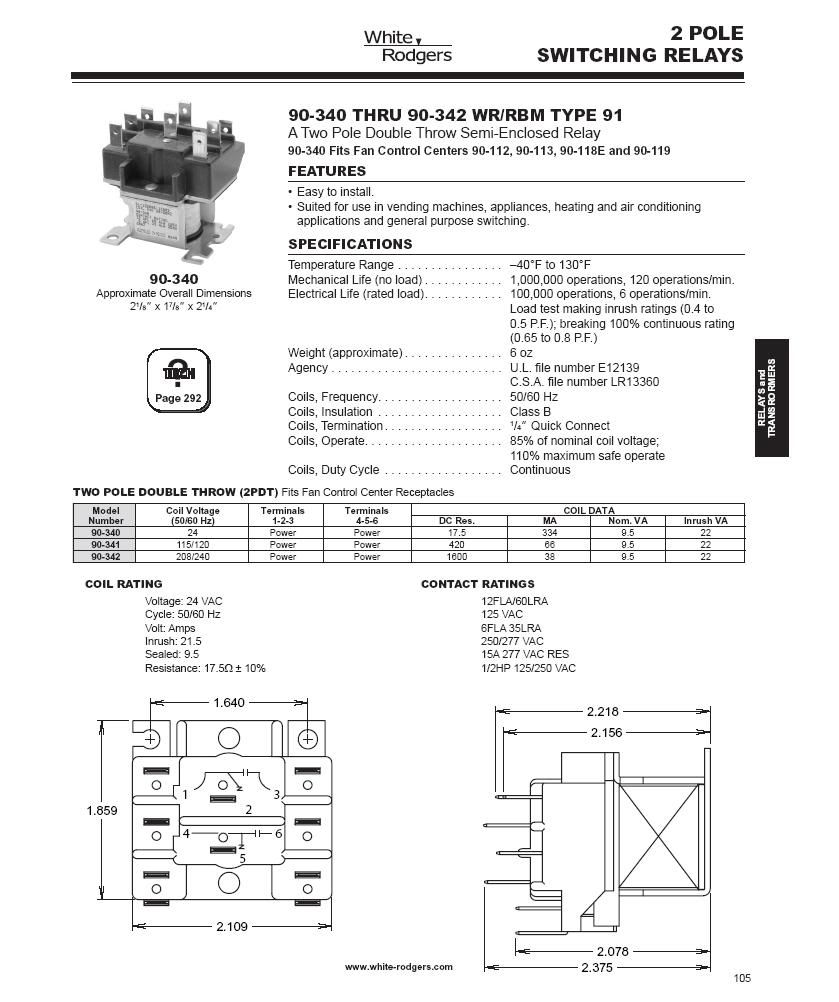
White Rodgers 1311 User Manual - ManualMachine.com View and Download White Rodgers 1311 instruction manual online. ... Make connections to screw terminals according to wiring diagram. NOTE: To check motor operation without thermostat connected, jumper 4 to 5 to open valve; jumper 5 to 6 to close valve. ... Do not attempt to wire two or more zone valves in parallel to operate from a single ...
![[Download 45+] White Rodgers 2 Wire Zone Valve Wiring Diagram](https://i.ytimg.com/vi/lYvHKg85Rnw/maxresdefault.jpg)
[Download 45+] White Rodgers 2 Wire Zone Valve Wiring Diagram
White Rodgers 1311 102 Wiring Diagram Sample 28.09.2020 · Name: white rodgers 1311 102 wiring diagram – Size of Wiring Diagram Taco Zone Valve Wiring Diagram New Contemporary Warm Zone Wiring File …

White Rodgers Zone Valve Wiring Diagram | Free Wiring Diagram
White Rodgers 3 Wire Zone Valve Wiring Diagram - alejandrarori White Rodgers F19-0097 - 3 Wire Motor Assembly For Zone Valves - Motor Assembly For Zone Valves 3 Wire Type For use with the following White-Rodgers zone valves. 7a Diagram for Gas-Fired System. Currently the red from transformer attaches to white wire from thermostateat 1st zone valve and white of transformer to 3 of zone valve.

White Rodgers Zone Valve Wiring Diagram : White Rodgers 3 Wire Zone ...
white rodgers thermostat wiring White-rodgers recalls home heating and cooling thermostats due to fire. White rodgers zone valve wiring diagram. Rodgers thermostat wiring diagram thermostats m100 programmable non 1f78 heat cool mechanical emerson installation voltage terminal hvac lead industry pro

White Rodgers Gas Valve Wiring Diagram - Gas Control Valve Wiring ...
White Rodgers Zone Valve Wiring Diagram - Magazine Order Now 08.03.2021 · White Rodgers 3 Wire Zone Valve Wiring Diagram Likewise White White Rogers Thermostat Wiring Diagram. White Rodgers - 1 Sweat Zone Valve Two Wire - 1 Sweat Zone I switched to the enclosed fitting made the connections and bled the air out of the. The old tstat had red-to-red white-to-white and the green wire attached to the Y terminal on a Honeywell series …

Wiring Diagram: 34 White Rodgers Zone Valve Wiring Diagram
White Rodgers zone valve wiring - DoItYourself.com Community Forums It's quite possible that your White-Rodgers zone valves require three-wire (SPDT) thermostats for operation. W-R made several such zone valves and they require the thermostat to close red to white to open the valve on a coll for heat and then to open the red/white connection and close red to the other color (in this case green) to close the valve.
White Rodgers Zone Valve Wiring Diagram - General Wiring Diagram
1361 102 White Rodgers Zone Valve Wiring Diagram White Rodgers 3/4 in. Water Sealant Replacement Kit for Zone Valves. diagramweb.net TECHNICAL HELP R W 1 3 4 5 2 TO AUXILIARY CIRCUIT. SCHEMATIC OF VALVE Two Wire Zone Valve TROUBLESHOOTING:) Attach a voltmeter to terminals and 2. Power (24 volts) should always be present on and 2. If power is interrupted check WIRING RESIDENTIAL ZONE VALVES.

White Rodgers Zone Valve Wiring Diagram
White Rodgers Zone Valve Wiring - diagramweb.net 09.06.2018 · White Rodgers Zone Valve Wiring White Rodgers Zone Valve Wiring White Rodgers - 3/4" Sweat Zone Valve (Three Wire) - 3/4" Zone Valve (Three Wire) Features 15 PSI Maximum Differential Across Valve Degrees. …
White Rodgers 3 Wire Zone Valve Wiring Diagram
Zone Valve Wiring Manuals Installation & Instructions: … The Load wire is taken to Terminal #1 on the White Rogers zone valve so that when it makes aux switch #2 there is no voltage across the switch, and the load is taken TO the thermostats directly for the Honeywell zone valves, and The …
A Hot Water Zone Valve Wiring Diagram - Wiring Diagram Networks
PDF TYPE 1311 - SupplyHouse.com If the boiler manufacturer recommends a wiring diagram, follow his instructions. If none are available, the following diagrams show suggested circuits for Type 1311 Water Valves in conjunc- tion with other W-R controls. A 40 VA transformer will handle up to four (4) water valves. A 20 VA transformer will handle up to two (2) water valves.
White Rodgers Zone Valve Wiring Schematic - Wiring Diagram

White Rodgers Gas Valve Wiring Diagram - Free Wiring Diagram

1361 102 White Rodgers Zone Valve Wiring Diagram
0 Response to "43 white rodgers zone valve wiring diagram"
Post a Comment