43 fuel oil tank installation diagram
H.F.O ( Heavy fuel oil ) Bunker line diagram - Marinerspointpro Of pump or tank depend on ship to ship but basic idea is same for all ship. This is rough sketch which help you to draw line diagram of your ship. Tanks used in H.F.O is 1.H.F.O Service Tank 2.H.F.O Settling Tank 3.L.S.H.F.O Service Tank 4.L.S.H.F.O Settling tank 5.L.H.S.F.O Storage Tank (p ) 6.H.F.O Storage Tank (p ) 7.No.1 H.F.O Storage Tank (s ) How To Install Residential Heating Oil Tanks Place your tank at least five feet from any fuel-fed appliance and from any kind of heat source. You need to be able to walk around the tank and see all four sides of it clearly. 18 inches of clearance all the way around the tank should be sufficient but do verify this with your local building official.
PDF FLOW DIAGRAM OF FUEL OIL SYSTEM (SSF DIESEL ENGINES).Sheet 1 of 1. fuel oil to diesel is to in pipe specifica71t* oss-e4a a. 2'. n-rj 1/2* n-rj e. cp with a to tx xØØØl set nessi.Æ psig ax ftÆl ort so 1/2- to fl.-el on- ecircu-at1œa 2 oil rev. per oe-6345 ed. c. 11 0.6 retired exe>ptic date cate cate civil elec. oconee a istec rture condition 1 power nuclear station units 1, 2 & 3 flow diagram of fuel ...

Fuel oil tank installation diagram
New MARPOL requirement on designated fuel oil sampling points … 25/06/2021 · Fuel oil samples under MARPOL. Following the new amendments there are now three defined fuel oil samples under MARPOL, each provided with a set of IMO guidelines: MARPOL delivered sample 1) – this is the traditional sample taken during bunkering, accompanying the Bunker Delivery Note (BDN) and which represents the fuel oil delivered on … Wiring to Switch Diagram - OPEengines.com Fuel Tank; Gauges; Kohler Front Drive Adapters; Kohler Oil Switches; Kohler Pressure Switch; Meters; ... Kohler Air-Fuel-Oil Hoses. Air Cleaner; Fuel Lines; Hose; Oil Hoses; Kohler Ignition Parts. Boots; Brackets; Brakes; Coils - Modules; ... Wiring to Switch Diagram. We Also Ship Saturdays* 888-652-3990. Have you seen ... Free Shipping & No ... ALLDATA Cookie Notice. We use cookies to keep our products working properly, improve user experience, analyze site traffic through our analytics partners, and serve targeted communications.
Fuel oil tank installation diagram. PDF Roth Double-Wall Oil Storage Tank Installation Instructions 5 Multiple Tank Installation Instructions (2-5 Tanks) 12 Initial Considerations 12 Indoor Installations 12 Roth Expansion Kits 12 ... SU2258 and approved under NFPA 31 (2001) and CSA B-139-04 as non-metallic fuel oil storage tanks. Other codes may be in effect in your area and may impose additional restrictions. If you have any Diesel Pumps - Fuel Transfer Pumps - Fuel Tank Shop Diesel fuel dispensing pumps for accurate and safe dispensing of fuel. Electric operated pumps. Self Priming and Non-Self Priming pumps. 12v, 24v, 110V and 230V pumps available.. A large range of industry trusted pumps such as Piusi, FMT, CEMO & Honda and a wide selection of rotary and hand pumps can be used to fit any assembly required.. If you require anymore … PDF An Engineering Guide to Modern Fuel Systems A system designer should be aware of a couple of key points when in- volved with boiler fuel oil systems. 1) Most boilers firing fuel oil will have their own fuel oil pump. 2) This pump can typically handle a low suction pressure of 15‖Hg without difficulty but a high suc- tion pressure of over 3 psig can cause the failure of the pumps seals. Heating Oil Tank Installation Guide - Certas Energy All heating oil tanks should be fitted with a gauge to measure how much oil is left. It's worth keeping a note of this to see how much you use over a given period. Also, to prevent overflow, you should keep your tank filled to around 80-90% capacity. The importance of proper installation
Site Map - AutoZone 20% off orders over $100* + Free Ground Shipping** Online Ship-To-Home Items Only. Use Code: DEAL4JULY Above Ground Fuel tanks Electrical Requirements: A Brief Study Let's take a look at them in detail: • Aboveground tanks should be installed at least 25 feet away from any building or electrical equipment. The wiring methods should be sanctioned for safety. Since you will be keeping gasoline and petroleum fluids, the vessel must be marked to demonstrate the class, group, and temperature range. PDF DIAGRAM OF A TYPICAL HEATING OIL AST SYSTEM - Maryland • Are you using an average amount of oil for your system? Using more oil than normal usually indicates a problem with your system. CONTACTS For further information on the inspection of heating oil AST systems, please contact the Oil Control Program at (410) 537-3442 or (800) 633-6101 x3442. To report oil spills call 1-866-633-4686. Fuel Oil System Installation - UpCodes The fuel oil system shall be sized for the maximum capacity of fuel oil required. The minimum size of a supply line shall be 3 / 8-inch (9.5 mm) inside diameter nominal pipe or 3 / 8-inch (9.5 mm) outside diameter tubing.The minimum size of a return line shall be 1 / 4-inch (6.4 mm) inside diameter nominal pipe or 5 / 16-inch (7.9 mm) outside diameter tubing. ...
Guidelines for Installing Above Ground Oil Tanks Joints in the piping should be made fuel oil tight by using joint compound. Vent pipe must measure 2in nominal. Installing Above Ground Oil Tanks Details: All tanks must be connected to a vent alarm which is a way to prevent spills. The fill pipe must measure 3ft above the grade. The vent pipe measures 6in above the grade. Oil Tank Fill & Vent Piping Installation & Inspection The oil company recommends going to 2", and most new installations use a two-inch diameter vent pipe; we've seen vent piping as small as one inch on oil tanks. During fill fuel is delivered at an average rate of 60 or even 70 gallons per minute. Improper or blocked oil tank air exit venting can place excessive stress on tank seams and piping. TYPICAL UNDERGROUND FUEL OIL TANK - U.S. Tank Tech TYPICAL UNDERGROUND FUEL OIL TANK. TYPICAL UNDERGROUND FUEL OIL TANK. This is a transparent view of a typical underground residential fuel oil tank. It shows how the pipes are usually connected to the tank. The three main connections are; the FILL PIPE, the VENT PIPE, and the FUEL OIL LINES. Each will be explained in more detail below. Lanair Waste Oil Heaters Take control of your heating cost with a waste oil heater from Lanair. Our heaters not only eliminate the cost to haul used oil off-site, but they can reduce your heating bills too. Sales - 800-562-5504 • Parts & Service - 888-370-6531
![Case 580E 580SE Repair Manual [Tractor] « YouFixThis](http://youfixthis.com/wp-content/uploads/2014/05/2016-01-13_9-17-30.jpg)
Case 580E 580SE Repair Manual [Tractor] « YouFixThis
Oil & Fuel 2638 Fuel Tank manufacturing issue - warning The tank is completely redesigned to not use bolts at all on the tank but straps and a new mounting system. So, word of caution, keep an eye on your fuel tanks, I'm not sure how the warranty works on items like this beyond the two year mark but after seeing first hand the design I can't imagine if they didn't get stressed during assembly ...

Fuel Oil: What Is Fuel Oil System
PDF Installation & Operation Manual - Tramont Day Tank Installation: Main Tank Below Day Tank, Piping Above Day Tank Remote Supply Pump with Day Tank Mounted Return Pump 6. Depending upon distance and lift, it may be possible to locate pump on the Day Tank. The pump lift and head worksheets on page 20 can be used to help estimate requirements.

Medium Velocity Water Spray (MVWS) System | Electrical4U
Chapter 13 Fuel Oil Piping and Storage - UpCodes Section 1305 Fuel Oil System Installation 1305.1 Size The fuel oil system shall be sized for the maximum capacity of fuel oil required. The minimum size of a supply line shall be 3 / 8 -inch (9.5 mm) inside diameter nominal pipe or 3 / 8 -inch (9.5 mm) OD tubing.
32 Fuel Oil Tank Installation Diagram - Wiring Diagram List
How to Install a Heating Oil Tank | eHow Install metal legs onto the oil tank, if they are not already attached. It is a good idea to have tank legs measure 11 inches at the outlet end and 12 inches at the other end. This gives the tank a slight slope and helps provide adequate room for the shutoff valve and filter. Legs typically screw into the base of the oil tank. Step 5

FUEL SYSTEM
PDF Installation Instructions - Double-wall Lubrication Oil Tanks The outer tank sides and bottom are formed from one sheet of steel, which is then shaped to receive the panels used at each end of the tank. The seams are caulked and then rolled in a three step robotic procedure, producing a strong, fluid tight and weld-free joint. 5. Each inner and outer tank is tested for defects and liquid tightness.
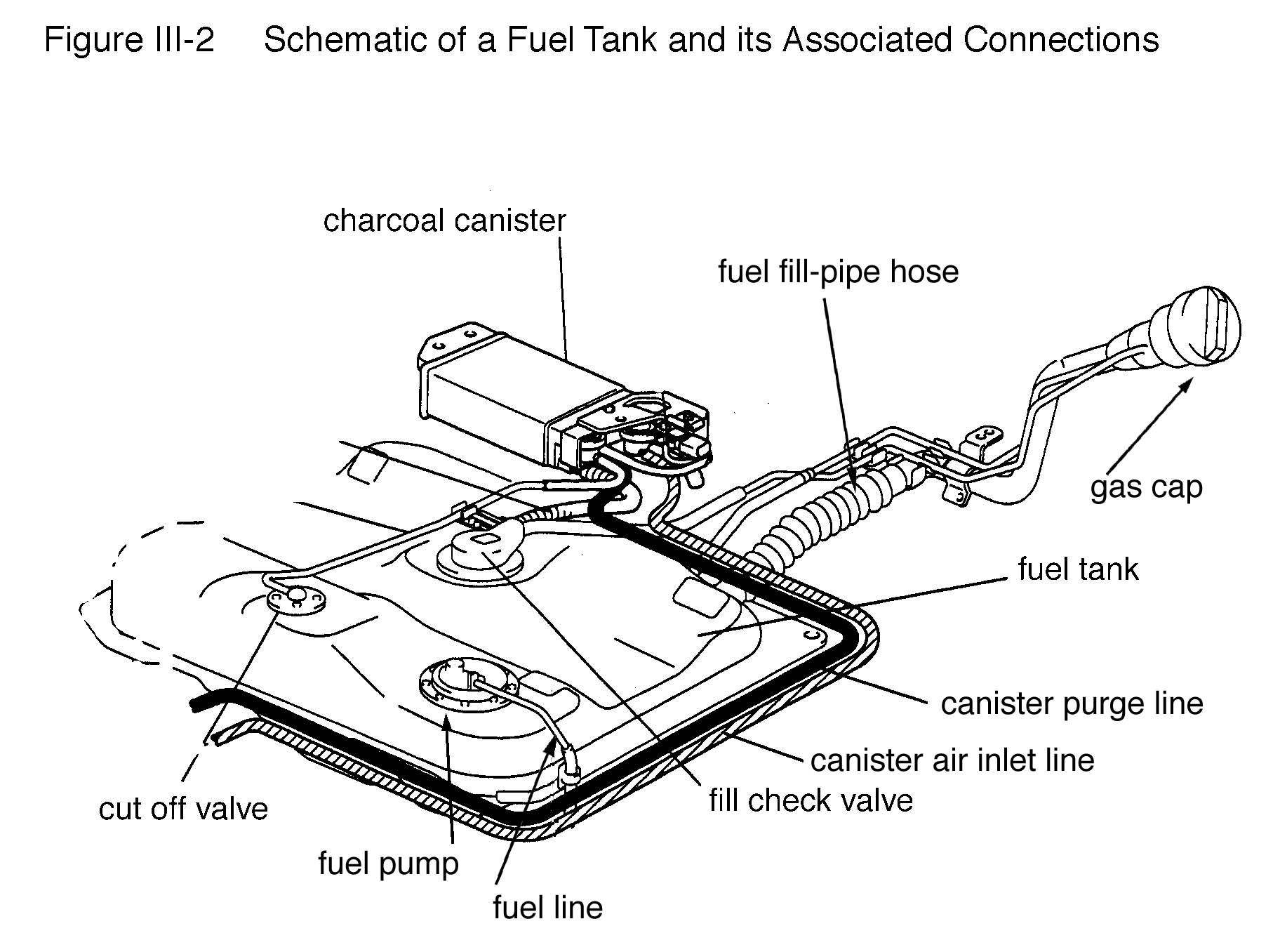
Schematic of a Fuel Tank and its Associated Connections
How to Install an Electric Fuel Pump in Your Classic Chevy Keeping the electric pump far away from the gas tank: Electric fuel pumps don’t pull fuel as well as they push it. So, you want to install it close to the gas tank for optimal performance. Mounting the fuel line close to heat sources: Fuel and heat don’t mix (at least outside of the engine). Keep the pump and fuel line away from the exhaust ...

Craftsman 316731973 gas line trimmer parts | Sears PartsDirect
PDF Fuel Oil Piping Systems Installation Instructions Fuel Oil Piping Systems Installation Instructions rather than sharp angles. The bottom of the trench should be compacted and as uniform as possible to eliminate high spots to insure an even layer of bedding material under the pipe. Remove all sharp rocks and debris from the trench bottom before bedding material is installed.
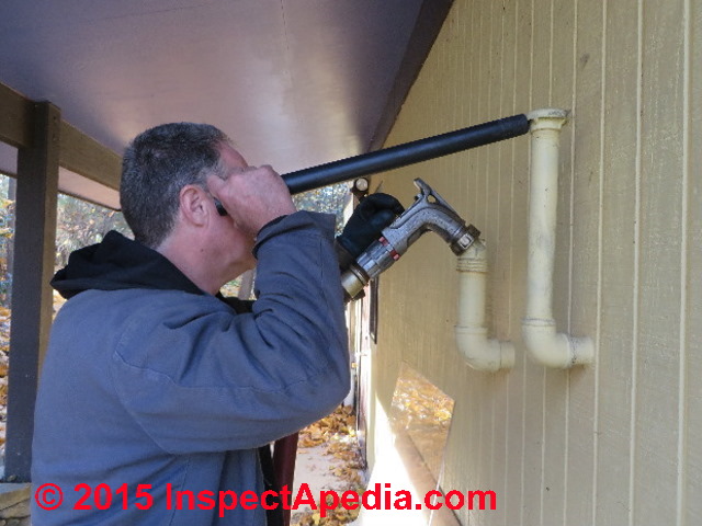
Oil Tank Fill & Vent Piping Installation & Inspection
Installation of Diesel Fuel Tanks for Fire Pumps Jan 15, 2014 · A review of the tank chapter in NFPA 30 for fixed tanks with capacity of 119 gallons or more finds no requirement stating that the connection to the engine has to be from the top of the tank, if the tank is on the floor on legs, or otherwise above ground. There are numerous requirements for the construction of a diesel fuel tank.

32 Fuel Oil Tank Installation Diagram - Wiring Diagram List
PDF READY Oil Tanks and Piping Chapter - noraweb.org The outside oil line should be connected through the top of the tank and insulated to where it enters the building. Once the line is inside, it should be connected to a thermal shut-off valve. The oil filter should NOT be installed outside. It can be installed right after the valve where the line enters the building or at the burner.

| Repair Guides | Diesel Fuel System | Tank Assembly | AutoZone.com
Parts of an Oil Tank - Smart Touch Energy Tank. Oil tanks are durable enough to last for years in a variety of different weather conditions. Depending on their size and the energy needs of the building, they can hold anywhere from 250 to 1,000 gallons of heating oil. Tanks are typically either steel or plastic and can be indoors, outdoors or even underground. There are three different ...
Fuel Systems info - 101
Fuel Oil Tank Installation Diagram - HeatFleet A full tank can weigh as much as a ton. Step 3 To catch and contain any leaks you might face from your oil tank, install a drip pan in the spot where you plan to install your oil tank. Step 4 Having metal legs on your oil tank (as shown in the diagram) is extremely important.
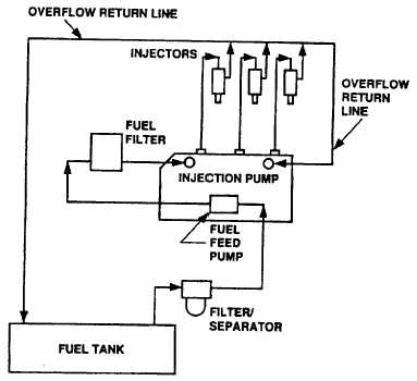
Figure 1-5. Fuel System Functional Diagram
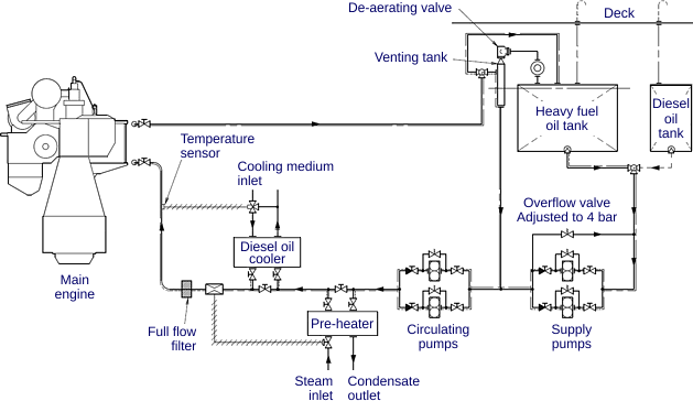
Fuel Oil System Diagram on Ship with Diagram Marine Diesel Engine The diagram below shows a Fuel oil supply system for a large 2 stroke crosshead engine In the system shown in Figure, the oil from the service tank flows through a three-way valve to the supply pump. After that it goes to the mixing column through a filter and flow meter. A flow meter is fitted into the system to indicate fuel consumption.

Figure 5-4. Fuel Lines and Tank - Exploded
PDF Fuel Oil Piping System Part 1 - General A. Deliver fuel oil system components in factory-fabricated water-resistant wrapping. B. Handle fuel oil system components carefully to avoid damage to material component, enclosure and finish. C. Store fuel oil system components in a clean, dry space and protect from the weather. PART 2 - PRODUCTS 2.1 PIPE AND FITTINGS:
Cisterns and Underground Tanks
PDF DOMESTIC OIL TANK BASES CONSTRUCTION AND DESIGN - Commercial Fuel Solutions Minimum height of the piers is 150mm thus allowing relatively low level steel tank installations to be created. The 150mm minimum dimension enables:- 1. Air movement around the tank to help prevent corrosion. 2. Visible routine inspection of the underside of the tank to be made. 3.

I have a 2005 150hp Yamaha 4 stroke that is sucking air some where (I ...
Heating Oil Tank Charts and Calculator | 275 Gallon Oil Tank Chart The 275 gallon horizontal (flat) tank is almost the same shape as its vertical counterpart, but it lays flat on its side for low-clearance installations. These are much less common than the vertical tanks but are still used relatively often in crawl spaces and under decks. These tanks are usually filled to about 250 gallons.

industrial valves manufacturers industrial valves market industrial ...
PDF Fuel Oil System - Uniri aIn the system shown in the diagram above the oil is stored 1 through a three-way valve to a mixing tank. bAfter passing through centrifuges 2 to indicate fuel consumption. cFrom the daily service tank the oil flows 3 in tanks in the double bottom from which it is pumped to a settling tank and heated.

Tanks and Filters (Automobile)
900MA/MAM and 1000MA/MAM - Parker Hannifin fuel tank is higher than filter Fuel tank below filter Do not exceed 5’ (1.5m) of lift or 4 inches of mercury (inHg) of inlet piping restrictions Fuel Tank (Ideal Vacuum Side Installation) Fuel Tank (Vacuum Side Installation) Install a check valve (with light or no restriction) when tank is lower than filter to maintain prime. Pressure Side:
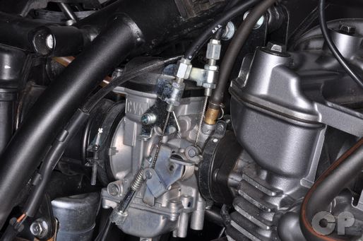
KLR650 Kawasaki Online Service Manual - Cyclepedia
Oil Tank Installation Guidelines | Quick Environmental Tanks shall be installed on the lowest floor of the dwelling Inside tank(s) shall be located not less than 5 feet (1.5 m) from any fuel-fired equipment The tank shall be placed in an area where it is unlikely to be adversely affected by normal household activities Tanks shall be placed in an area where they can be visually inspected from all sides.
0 Response to "43 fuel oil tank installation diagram"
Post a Comment