42 usb killer circuit diagram
USBKill | USB Kill devices for pentesting & law-enforcement The USBKill has been designed and tested to be safe and efficient. It is both CE Approved and FCC Approved, and built and tested with the utmost priority on user safety. Although totally safe to operate, the USBKill is a high voltage device - and should be treated with appropriate precautions. Givenchy official site Our team is available Mon-Sat 10:00-19:00 to answer your questions in French, Italian or English. Email contact@givenchy.com; Send a message
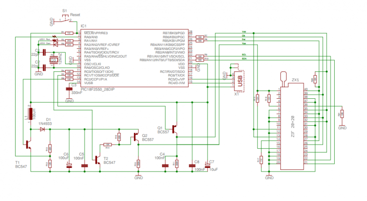
USB KILLER V3 reverse engineering in progress UPDATED - EEVblog After some research, all I found out about this thing is some pictures of the PCB and a partial list of the components so I decided to buy one in order to reverse engineer it. I managed to unsolder all the components properly so I could extract the schematic out of it. Here are the pictures where you can see clearly the PCB and the components:

Usb killer circuit diagram
2 Mosquito Swatter Bat Circuits Explained When this circuit is applied as a mosquito swatter, the end terminals of the 2uF capacitor are appropriately tied or connected across the internal and the external bat mesh layers. These metal mesh layers are woven and positioned tightly over a sturdy plastic frame in such away that these are held apart at some distance. Surface Mount Device (SMD) Tape and Reel | Maxim Integrated Maxim surface-mount packages are shipped in antistatic plastic rails. For customers using automatic placement systems, parts also come mounted in pockets on embossed tape. The tape is wound and shipped on reels. The table and diagram on this page indicate the tape sizes used for various package types and the basic orientation convention used ... Power Bank Circuit for Smartphones | Full Circuit Explanation Circuit and working for power bank. Circuit diagram of the power bank is shown in Fig. 1. It consists of a USB lithium-ion charger module (USB-IN), 3.7V/2600mAh lithium-ion battery (BATT.1), on/off switch (S1) and DC-DC boost converter module (USB-OUT). Here, a lithium-ion charger module based on TP4056 IC, rechargeable lithium-ion battery ...
Usb killer circuit diagram. source.android.com › devices › bluetoothBluetooth | Android Open Source Project Jun 14, 2021 · A Bluetooth system service communicates with the Bluetooth stack through JNI and with applications through Binder IPC. The system service provides developers with access to various Bluetooth profiles. This diagram shows the general structure of the Bluetooth stack: Figure 2. Android 7.x and earlier Bluetooth architecture USB KILLERS EXPLAINED ~ electrical and electronics USB killers consist of an few oscillators, a step up transformer and a few capacitors. At first the oscillator circuit takes 5-6 volts from the USB port when connected to a USB peripheral (for example USB port on your computer), and it drives the transformer which is step up function. gioielleriapegy.it › kenwood-dpx501bt-resetKenwood dpx501bt reset DPX501BT. TM-221A/321A/421A/521A – With the power off press the VFO/M, & M. plCar stereo reviews: the best double-DIN head units 2021 Audio amplifier circuit diagram with layout pdfRemington rm4620 parts diagram1st Gen. 12. From: [email protected] 11 Although parts and price information is Kenwood dpx501bt wiring diagram for your needs. CD ... How to Make an USB Killer : 3 Steps - Instructables Step 2: Circuiting 1. Open case of the Mosquito Zapper and remove the circuit 2. Remove the discharging capacitor at output of the circuit. 3. Solder USB female jack in place of removed capacitor. 4. Solder USB male jack to the Capacitor removed as shown in circuit and place in the USB case . 5. Apply electric tape for more safety. 6.
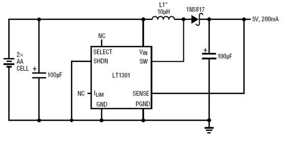
How to Use an Arduino : 5 Steps (with Pictures) - Instructables Step 3: Project 1: Blink. Open the Arduino IDE and create a new sketch. Click on the Open tab and find examples. Find the blink sketch and open it. Upload it to your board. If you'd like, you can add an external LED to the board, by inserting the positive lead of the LED into digital pin 13 and inserting the negative lead into the ground pin. The USB Killer, Version 2.0 - hackaday.com The USB Killer v2.0 is [Dark Purple]'s second version of this device. The first version was just a small board with a DC/DC converter, a few caps, and a FET. When plugged in to a computer, the... thinkgeek | Search Results | GameStop View all results for thinkgeek. Search our huge selection of new and used video games at fantastic prices at GameStop. How to create an USB killer - Quora Answer (1 of 5): Well usb killer thing sound's cool but there is nothing like usb killer. You have to pay for an official killer and also it's not legal. But you can create a Trojan or malware in usb which can format a PC or hang it. You can made one by notepad. You can find many ways of creating...
What is a USB Killer ? Why They Use It? - YouTube The USB Kill Tester Shield is a dual purpose device: - It allows you to test your USB Kill 2.0 without damaging your host device. - It prevents data theft via 'juice-jacking' If you use a charger... USB pinout, wiring and how it works! - ElectroSchematics.com USB A, B 2.0 and 3.0 Cable Pinout. The USB cable provides four pathways- two power conductors and two twisted signal conductors. The USB device that uses full speed bandwidth devices must have a twisted pair D+ and D- conductors. The data is transferred through the D+ and D- connectors while Vbus and Gnd connectors provide power to the USB device. October 2017 Circuit Diagram USB Standby Killer Circuit Diagram: This so-called 'USB-standby-killer' can be realised with just 5 components. The USB output voltage provides for the activation of the triac-opto driver (MOC3043) which has zero-crossing detection. This, in turn, drives the TRIAC, type BT126. Mosquito Zapper Circuit Diagram and Theory of Operation Design. We know that electronic mosquito zappers usually come exactly in the form of a badminton racket, and quite similarly have a net woven over its top circular frame; whereas the handle part consists of an electronic circuit and a battery pack integrated with the net assembly. The net structure is primarily made up of three layers of metal ...
usb circuit Page 9 : Computer Circuits :: Next.gr
USB Standby Killer Schematic Circuit Diagram The USB output voltage provides for the activation of the triac opto-driver (MOC3043) which has zero-crossing detection. This, in turn, drives the TRIAC, type BT126 The circuit shown is used by the author for switching loads with a total power of about 150 W and is protected with a 1-A fuse. The circuit can easily handle much larger loads however.

USB Standby Killer | Circuits-Projects
howtomechatronics.com › projects › diy-air-qualityDIY Air Quality Monitor - PM2.5, CO2, VOC, Ozone, Temp & Hum ... We can power the air quality monitor through the Mini USB connector and we can get the 5 volts from a 5V USB adapter, a 5V phone charger or a power bank. For uploading the program to the Arduino Pro Mini board, we need an USB to serial UART interface which can be connected to the programming header.
USB Device Charger
USB interfacing with PIC microcontroller with code USB interfacing circuit with pic microcontroller. Make the circuit diagram as shown in the schematic: The input voltage to a PIC18F4550 Microcontroller should never exceed 5 V. The crystal oscillator used is 20MHZ crystal oscillator which is connected on 13 and 14 pin. Short 11th and 32nd pin together to 5v, similarly 12th and 31st pin to GND.

USB-Powered PIC Programmer | Xtreme Circuits
USB Killer V3 [Standard & Anonymous] | CYBERPUNK CyberPunk Gadgets Introduction The USB Killer V3 is pretty much a simple device, initially developed by the security team based in Hong Kong, having a few high voltages, a FET, a DC/DC converter and a USB connector. Once plugged into a targeted device it will cycle voltage (charge/discharge 220V) until something drops dead.

Schematic diagram of a USB player - Circuit Schematic Electronics
This terrifying homemade USB killer will instantly kill your computer Maybe you've heard of the USB killer, a $49 device that you plug in and fires a surge of power through your computer's motherboard if it's not isolated well enough — which is often the case. DIY...

USB-Powered PIC Programmer | Xtreme Circuits
› expert-adviceExpert Advice | BoatUS Apr 20, 2022 · From BoatUS Magazine, America's Most-Trusted Boating Magazine. BoatUS Magazine, official publication of the Boat Owners Association of The United States (BoatUS), provides recreational boating skills, DIY maintenance, safety, news, lifestyle and personality profiles, and insight from top experts.

isolation - How do I correctly power a USB 2.0 while decoupled from ...
DIY Air Quality Monitor PM2.5 CO2 VOC Ozone Temp Hum … We can power the air quality monitor through the Mini USB connector and we can get the 5 volts from a 5V USB adapter, a 5V phone charger or a power bank. For uploading the program to the Arduino Pro Mini board, we need an USB to serial UART interface which can be connected to the programming header.

Push Switch Circuit - Electronics & Technical Hub
This "Killer USB" Flash Drive Will Explode Your Computer The basic idea of the USB drive is quite simple. When we connect it up to the USB port, an inverting DC/DC converter runs and charges capacitors to -110V. When the voltage is reached, the DC/DC is...

Schematic diagram of a USB player - Electronic Circuit
USB killer: What it is and how to protect your devices USB Killer is a modified USB drive that destroys computers when you insert it into the machine's USB drive. There are different versions of this device, and you can even create a DIY version yourself for $3 or less. USB Killer is often used as an example of why you should refrain from plugging in unknown USB devices into your systems.

DS
USB Wiring Diagram: A Complete Tutorial | EdrawMax This USB pin-out diagram shows the USB cable often connected to phones to charge them or transfer data. Type A connector is linked to the charger or PC, and a microSD connector is plugged into the phone. You can add labels to the wires, pinouts, and connectors to make your diagram more informative.
TL072 op-amp configured as voltage comparator under Repository-circuits ...
tubecad.comTube CAD Journal Jul 19, 2015 · — Since 1999 — Welcome to over 500 posts and to over 50 articles on amplifiers, tube-based preamps, crossovers, headphone amplifiers, single-ended amplifiers, push-pull amplifiers, Circlotron circuit design, hybrid amplifiers, cascode circuits, White cathode followers, grounded-cathode amplifiers, tube series regulators and shunt regulators, the Aikido amplifier, tranformer coupling, DACs ...

capacitor power supply, 5volt Power supply - Electronics & Technical Hub
source.android.com › devices › graphicsGraphics | Android Open Source Project Sep 15, 2020 · See the following diagram for a depiction of the Android graphics pipeline: Figure 2. Graphic data flow through Android. The objects on the left are renderers producing graphics buffers, such as the home screen, status bar, and system UI. SurfaceFlinger is the compositor and Hardware Composer is the composer. BufferQueue

Mosquito Bat Circuit Buy Online - Pest Control Diagram
Bluetooth | Android Open Source Project 14.06.2021 · A Bluetooth system service communicates with the Bluetooth stack through JNI and with applications through Binder IPC. The system service provides developers with access to various Bluetooth profiles. This diagram shows the general structure of the Bluetooth stack: Figure 2. Android 7.x and earlier Bluetooth architecture

Homemade Mosquito Killer Circuit
USB Standby Killer Circuit Diagram - Blogger USB Standby Killer Circuit Diagram: This so-called 'USB-standby-killer' can be realised with just 5 components. The USB output voltage provides for the activation of the triac-opto driver (MOC3043) which has zero-crossing detection. This, in turn, drives the TRIAC, type BT126.

Isolated USB to USB, RS232, RS485 by EsTools - Engineering Spirit ...
Expert Advice | BoatUS 20.04.2022 · From BoatUS Magazine, America's Most-Trusted Boating Magazine. BoatUS Magazine, official publication of the Boat Owners Association of The United States (BoatUS), provides recreational boating skills, DIY maintenance, safety, news, lifestyle and personality profiles, and insight from top experts.The award-winning boating magazine publishes several …
USB PIC Programmer - Electronics-Lab
Tube CAD Journal 19.07.2015 · — Since 1999 — Welcome to over 500 posts and to over 50 articles on amplifiers, tube-based preamps, crossovers, headphone amplifiers, single-ended amplifiers, push-pull amplifiers, Circlotron circuit design, hybrid amplifiers, cascode circuits, White cathode followers, grounded-cathode amplifiers, tube series regulators and shunt regulators, the Aikido amplifier, …

Forum Diagram: Simple Programmer AVR Your USB Wiring diagram Schematic
› types-of-satellitesTypes of Satellites | What is Satellite, Types and Uses of ... These satellites are placed in Space at different altitudes, and they are facing different planets depending on the applications. 63% of current operational satellites are at a low orbit level (< 2000 Km), 6% are at medium orbit level (< 20000 km), 20% are at the geostationary orbit level (< 36000 km) and the rest 2% at elliptic level (> 36000 km).
0 Response to "42 usb killer circuit diagram"
Post a Comment