40 Common Start Run Diagram
Wye Start Delta Run Motor Wiring ... - Wiring Diagram Sample Size: 28.38 KB. Dimension: 300 x 288. DOWNLOAD. Wiring Diagram Images Detail: Name: wye start delta run motor wiring diagram - STAR DELTA Starter Will always work over with your 5HP above rated motors. File Type: JPG. Source: pinterest.com. Size: 52.05 KB. Dimension: 236 x 329. Single Phase Capacitor Start Capacitor Run Motor Wiring ... Single Phase Capacitor Start Capacitor Run Motor Wiring Diagram from static-cdn.imageservice.cloud. Print the wiring diagram off plus use highlighters to trace the signal. When you make use of your finger or perhaps the actual circuit with your eyes, it is easy to mistrace the circuit. 1 trick that We 2 to printing a similar wiring plan off twice.
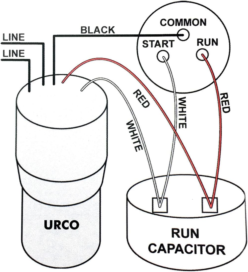
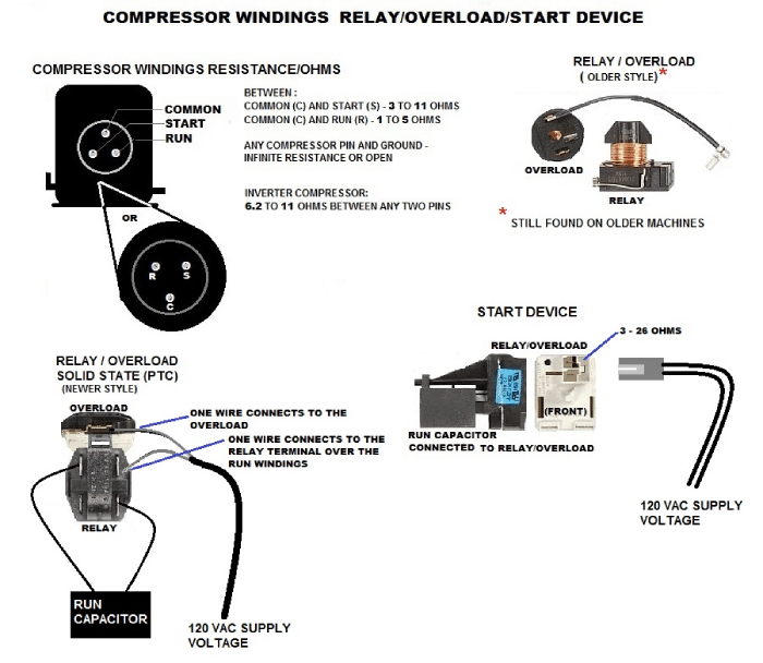
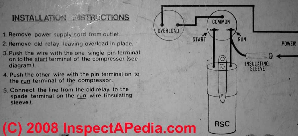
Identifying Compressor Terminals: Start, Run, and Main ... You need to figure out which posts correspond to the Start, Main, and Run windings 'cuz if'n you don't and you go and wire that relay/overload up wrong, well, you just went from a $30 easy-as-pie repair to a $300 rectal cramp.

Common start run diagram
Guide to Track Markings - TrackInfo.Org The set that is equidistant from common finish line is the 2nd and 3rd passing zone for the 4x400 relay, while the set that is staggered (equidistant from the one-turn stagger line in each lane) is the first passing zone, still in lanes relative to the blue, 3-turn stagger start line. To run the mile on a metric track, there should be a ... Start Capacitor Wiring Diagram - easywiring Start capacitor wiring diagram. Push the wire terminal on the start capacitor s second wire onto the run capacitor s common terminal often labeled c com the wire connected to the motor s run terminal marked as r on the motor s wiring chart and the wire going to the hot terminal on the load side of the contactor also connects to this run ... Embraco Compressor Wiring Diagram - Wirings Diagram Embraco Compressor Wiring Diagram - aspera compressor wiring diagram, embraco compressor wiring diagram, embraco egx70hlc compressor wiring diagram, Every electric structure is made up of various different parts. Each part should be placed and connected with different parts in specific way. If not, the arrangement won't function as it ought to be.
Common start run diagram. Solved: Find the common, start, and run terminals of the ... Find the common, start, and run terminals of the following hermetic compressors. a. b. c. Step-by-step solution. Step 1 of 4. (a) The following is the diagram for the terminals in the hermetic run compressor: Figure 1. Chapter 8, Problem 41RQ is solved. How to identify compressor common, start, run terminal ... Compressor common, start, run identifyIn this video we explain how to identify compressor common start run with multimeter by testing their resistance For id... › pages › uml-class-diagramUML Class Diagram Tutorial - Lucidchart Class diagrams are one of the most common types of diagrams in UML, and Lucidchart has made it easy to understand and create them. Jump right into one of our templates, import an existing class diagram and continue working on it within Lucidchart, or start from scratch. We have all the features and tools you need to get started. Single Phase Motor Wiring Diagram With Capacitor - Wirings ... Single Phase Motor Wiring Diagram With Capacitor - baldor single phase motor wiring diagram with capacitor, single phase fan motor wiring diagram with capacitor, single phase motor connection diagram with capacitor, Every electrical arrangement is made up of various unique pieces. Each component ought to be placed and linked to different parts in particular manner.
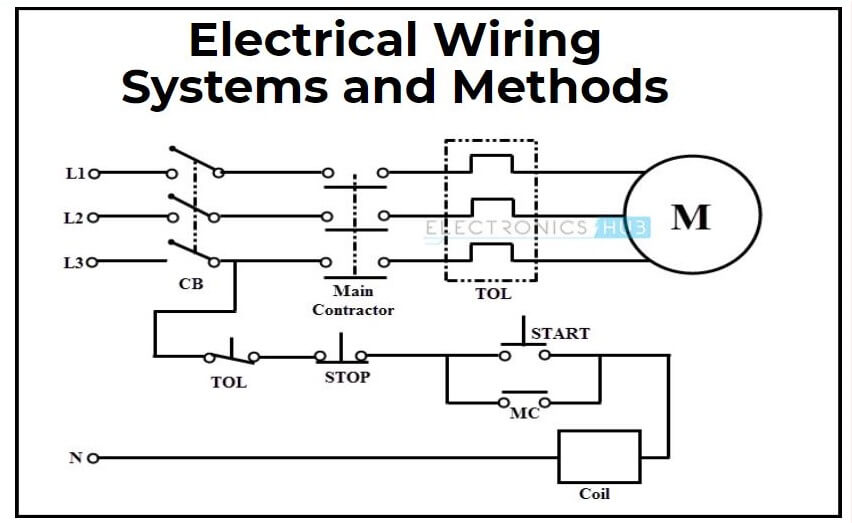
PDF Basic Wiring for Motor Contol - Eaton Wiring diagrams, sometimes called "main" or "construc-tion" diagrams, show the actual connection points for the wires to the components and terminals of the controller. They show the relative location of the components. They can be used as a guide when wiring the controller. Figure 1 is a typical wiring diagram for a three-phase mag- circuitglobe.com › capacitor-start-capacitor-runCapacitor Start Capacitor Run Motor - Circuit Globe The run capacitor is long time rated and is made of oil-filled paper. The figure below shows the Phasor Diagram of the Capacitor Start Capacitor Run Motor. Fig(a) shows the phasor diagram when at the starting both the capacitor are in the circuit and ϕ > 90⁰. How to Find Common, Start, and Run on a PSC Compressor Motor! In this HVACR Training article, we are using electrical resistance measurements on the PSC compressor terminals in order to determine which tab is Common, Start, and Run. This is used when the tabs are not labeled, there is no plug for the terminals, or there is no electrical wiring diagram available for the wires feeding from the terminals. The steps listed below can be used to test all ... Single Phase Motor Wiring Diagram With Capacitor Start ... Capacitor start run motor connection. Application of start and run capacitor for single phase motor. Read the wiring diagram on your appliance to understand the colors that the manufacturer designed for the three connections namely start run and common.
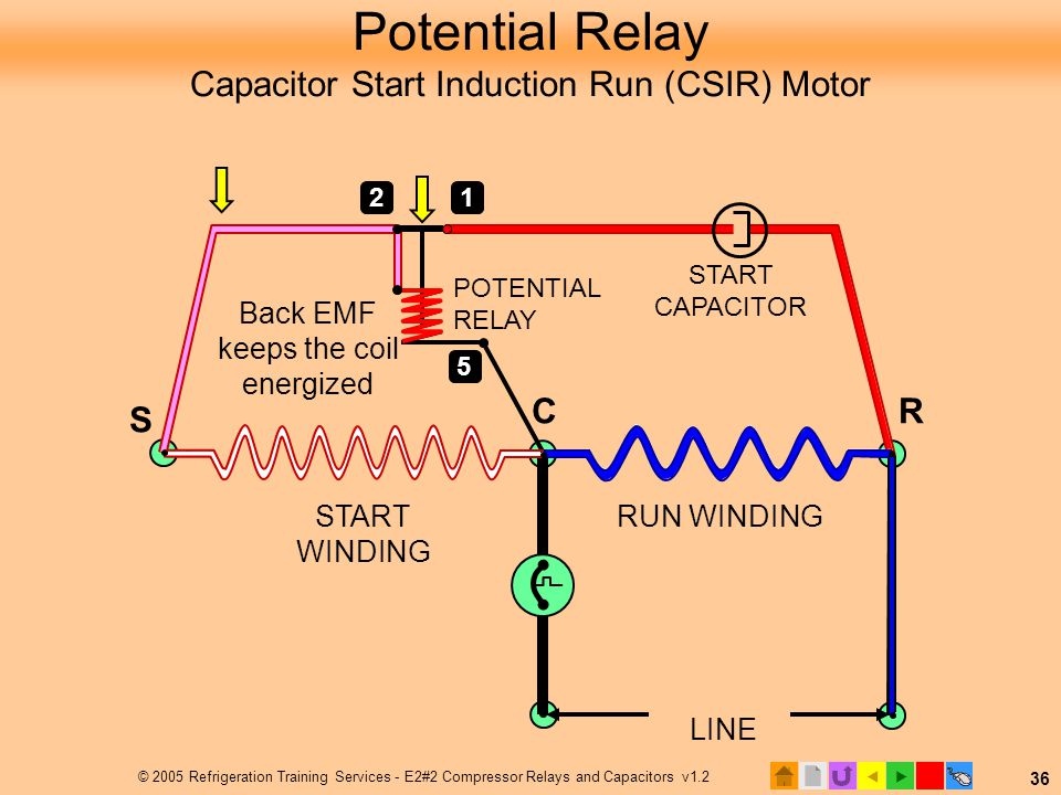
PDF COPELAND S H COMPRESSORS - Emerson Electric torque for automatic start and optimum operation, as in the case of three-phase motors, a capacitor and relay assembly consisting of a start and run capacitor and a potential relay will be supplied. Assembly must be in accordance with the position of the capacitors and relay shown on the wiring diagram. Embraco Compressor Wiring Diagram - schematron.org the prongs on my compressor. embraco egy90hlp wiring diagram.Also there is a diagram on the back of the package the shows you where to put the common, start, and run lead on the compressor, if it is a embraco compressor invert the diagram to match the stud coming off compresser. Compressor Wiring Diagrams: Refrigerant. docs.microsoft.com › en-us › azurePipeline run sequence - Azure Pipelines | Microsoft Docs Feb 11, 2022 · The following command lists the tags for the pipeline run with the ID 123 and returns the result in table format. az pipelines runs tag list --run-id 123 --output table Tags ----- YAML Delete tag from pipeline run. Delete a tag from a pipeline run in your project with the az pipelines runs tag delete command. How to Find Common, Start, and Run on a PSC Compressor ... In this HVACR Training Video, I show how to Measure Resistance Readings on the PSC Compressor Terminals in order to determine which tab is Common, Start, and...
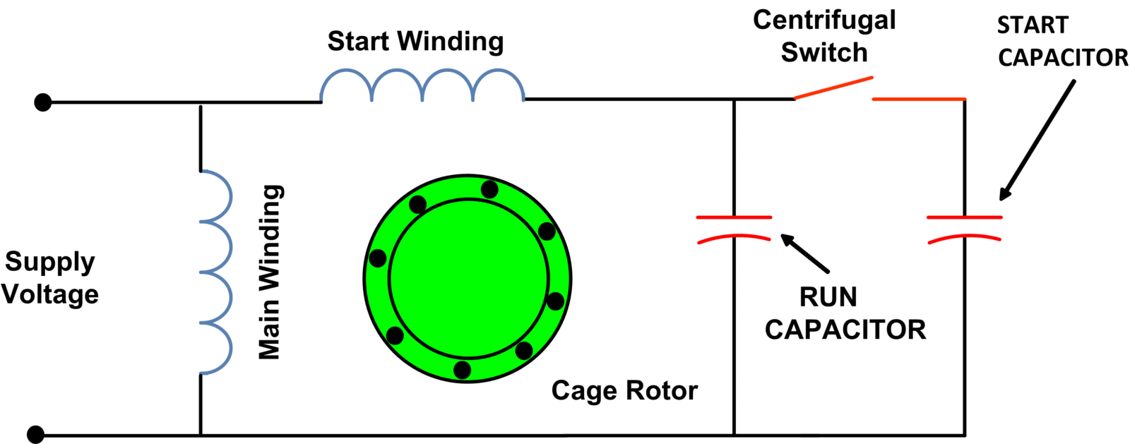
Capacitor-Start Capacitor-Run Induction Motor The phasor diagram of the capacitor-start capacitor-run motor is shown below. At starting both the capacitors are in the circuit, therefore, the phase angle φ is greater than 90°. When the starting capacitor (C S) is disconnected from the circuit, then the phase angle becomes 90° electrical.
How do you connect a start and run capacitor? How to Wire Up a Start Capacitor. Turn off the electricity to the unit the motor operates. Inspect the start capacitor's wiring diagram. Push the wire terminal on the start capacitor relay's "Common" wire, usually the black wire, to the common terminal on the load side of the unit's contactor. Click to see full answer.
How to Wire Up a Start Capacitor - Hunker Step 7. Push the wire terminal on the start capacitor's second wire onto the run capacitor's common terminal, often labeled "C," "COM." The wire connected to the motor's run terminal, marked as "R" on the motor's wiring chart, and the wire going to the hot terminal on the load side of the contactor also connects to this run capacitor terminal.
Tech Tip: Compressor Common - Run - Start | Ferguson HVAC When tripped, you will read infinity between start to common and run to common, but you will read resistance between run and start. You will have to let the compressor cool and the overload to should reset before further testing. Compressors can take hours to cool down and the overload to reset. Formula: CS + CR = SR.
Electric Motor Starting Capacitor Wiring & Installation Not used when using a dual start/run cap. Same use as white wire, C (common) on capacitor to T2 on contactor. Not used when using a dual start/run cap. Green: Ground wire in nearly all systems : Orange: From power terminal on fan motor to C or COM on the capacitor Compressor contactor relay T2 to C or COM or RC connector on the Run or Start/Run ...
inspectapedia.com › electric › Motor_Capacitor_TypesElectric Motor Starting & Run Capacitor Types, Installation ... Types of electric motor start & run capacitors: this article explains and gives an identification guide to types of electric motor capacitors: motor starting capacitor, motor run capacitor, dual-run capacitors, and hard start capacitors used on electric motors such as air conditioner & heat pump compressors, fan motors, some well pumps & some heating equipment motors.

55+5 MFD uF Air Conditioner Capacitor Round Aluminum Electrolytic Dual Motor Run Capacitor 450V AC Withstand Voltage for Straight Cool Condenser or ...
Single Phase Motor Winding Resistance -Start Run Common So the supply will be going to the common and run and the capacitor will be connected between the run and start. This is an explanation of single phase motor winding resistance, However, if you want to learn more about how to identify the start run and common in a single-phase motor then read the following articles for complete understanding...
› forum › threadsTechnical - Automotive wiring diagram software | The H.A.M.B. Jan 25, 2022 · I started drawing the overview diagram in Visio and it looks good, I am going to try to do maybe the lighting cct to start with and see how it looks, then carry on with the rest of the vehicle. I think I will stay with my "drawing by system" so that all lighting is on one page etc.
› blog › jeep-compass-reliabilityJeep Compass Reliability and Common Problems - In The Garage ... Vehicle Refuses to Start. A somewhat common 2018 Jeep Compass problem is a no-start condition. According to the affected owners, they first noticed the issue when the vehicle was still relatively new, at approximately 25,000 miles. One owner said that even if they had their vehicle checked at a mechanic, their vehicle still failed to start.
Three Phase Motor Winding Diagram Marmitteore Winding Resistance -Start Run Common Apr 03, 2018 · This post is about the single phase motor winding resistance testing with complete explanation. From this article you will learn about the single phase induction motor winding resistance, main winding, starting winding. And … Three-Phase Induction Motor Protection Systems and its Three ...
Network Diagrams in Project Management and IT | WGU A project network diagram is useful for planning and tracking a project from start to finish and organizing tasks within a project. It's usually depicted as a chart with a series of boxes and arrows. The most common method for creating network diagrams in project management is the precedence diagramming method (PDM).
What is Start Run Common In Single Phase Motor start run common diagram In the above example diagram, i shown two coil symbols, the running coil starting point is A and ending point is B.The starting coil starting point is C and ending point is D. So if we connect A and C then this will called the common because this point is connected with both coils.
Heatcraft Unit Cooler Wiring Diagram Heatcraft Unit Cooler Wiring Diagram. Wiring at the unit cooler (s) will be as follows (see wiring diagrams). • High voltage - There may be high voltage on the defrost heater relay and the fan relay. to your Heatcraft Refrigeration Products Sales Representative. Warranty Consult the wiring diagram in the unit cooler and in the condensing unit ...
Cscr Wiring Diagram - schematron.org This is a common question, and the answer may have a significant effect on how your motor runs, depending on its size and application. The diagram in Figure 1a shows the potential relay connected to a motor with a start and run capacitor. Note that the potential relay's contacts are connected in .
realpars.com › wiring-diagram-to-pHow to Convert a Basic Wiring Diagram to a PLC Program Mar 18, 2019 · To program a simple motor start-stop circuit, we need to read the electrical diagram from left to right and use our toolbox on the programming software. You will be using the most common bits in the examine ON, which will represent a normally open contact, examine OFF, which will represent a normally closed contact, and output coil or output ...
On a refrigerator compressor, which is the common, start ... The run terminal is usually on the right and the start terminal is on the left. To check this, (with the refrigerator unplugged) you could take resistance readings on the terminals. From the common to the start terminal, you should measure between 3 to 11 ohms. From the common to run terminal, you should measure between 1 and 5 ohms.
Capacitor Start Capacitor Run Motor Wiring Diagram Single Phase Motor Winding Resistance -Start Run Common Apr 03, 2018 · The motor in the picture with the extra two wire for the start capacitor is a little more tricky, but if you disconnect the capacitor and measure the resistance of ... Capacitor Start Capacitor Run Motor Wiring Diagram ...
How to Add the Run Command to the Windows 10 Start Menu The Run command, known to most users as "the Run box," has long had a convenient top-level shortcut in the Windows Start Menu. While the Start Menu returned in Windows 10, the Run command didn ...
Embraco Compressor Wiring Diagram - Wirings Diagram Embraco Compressor Wiring Diagram - aspera compressor wiring diagram, embraco compressor wiring diagram, embraco egx70hlc compressor wiring diagram, Every electric structure is made up of various different parts. Each part should be placed and connected with different parts in specific way. If not, the arrangement won't function as it ought to be.
Start Capacitor Wiring Diagram - easywiring Start capacitor wiring diagram. Push the wire terminal on the start capacitor s second wire onto the run capacitor s common terminal often labeled c com the wire connected to the motor s run terminal marked as r on the motor s wiring chart and the wire going to the hot terminal on the load side of the contactor also connects to this run ...
Guide to Track Markings - TrackInfo.Org The set that is equidistant from common finish line is the 2nd and 3rd passing zone for the 4x400 relay, while the set that is staggered (equidistant from the one-turn stagger line in each lane) is the first passing zone, still in lanes relative to the blue, 3-turn stagger start line. To run the mile on a metric track, there should be a ...











0 Response to "40 Common Start Run Diagram"
Post a Comment