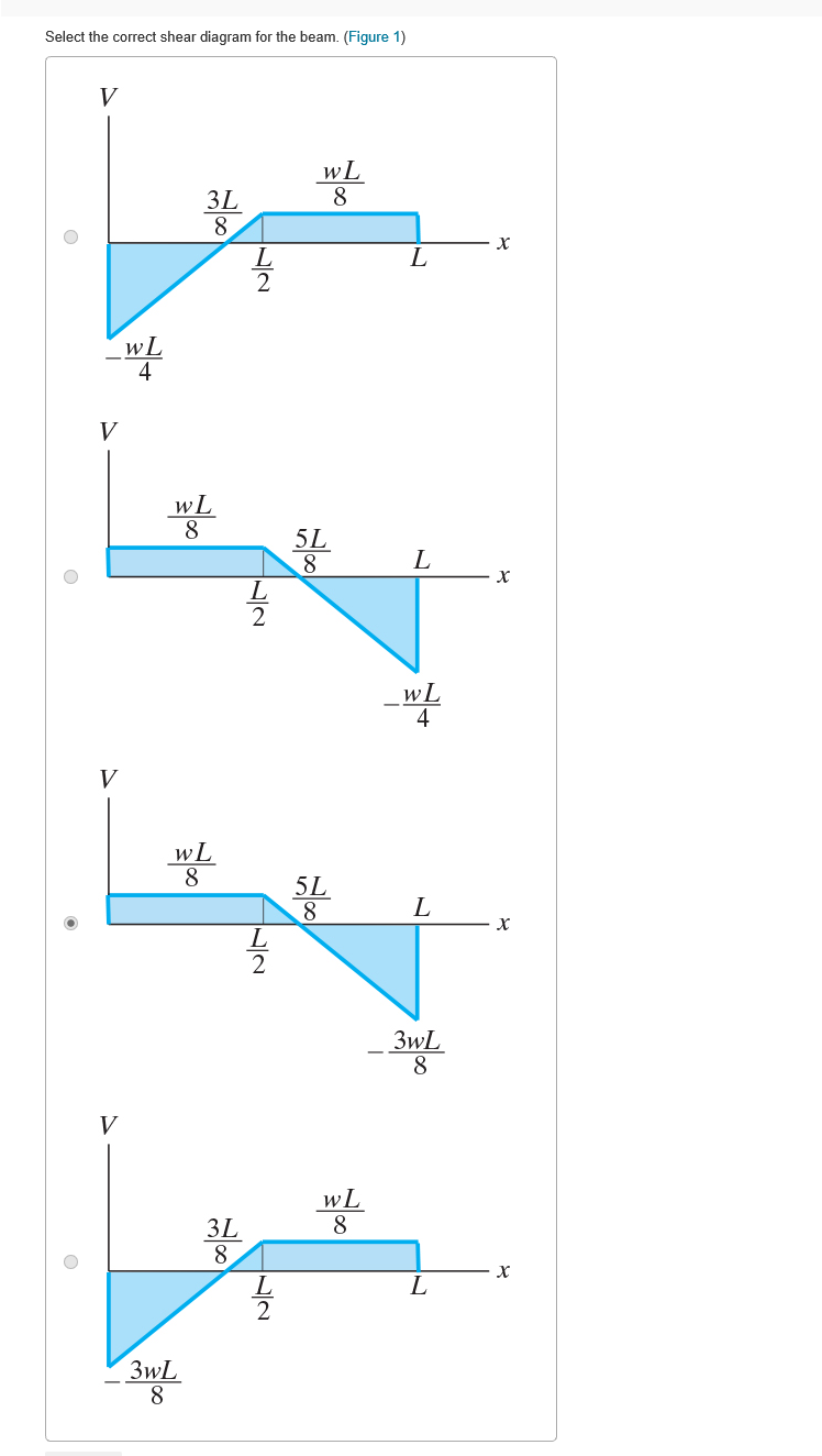
36 select the correct shear diagram for the beam. (figure 1)
Shear Force Diagram Of A Cantilever Beam - The Best ... Shear force bending moment diagram solved the correct shear force diagram shear force and bending moment of beams shear force diagram. ... Cantilever Beam Shear Force Diagrams Mechanical Ering. ... A Cantilever Beam Is Subjected To Various Lo As Shown In Figure Draw The Shear Force Diagram And Bending Moment For Ethiotutors. Part A Consider the beam shown in (Figure 1). Follow the ... Part A Consider the beam shown in (Figure 1). Follow the sign convention. Draw the shear diagram for the beam Click on "add vertical line off" to add discontinuity lines. Then click on "add segment" button to add functions between the lines. Note 1-You should not draw an "extra" discontinuity line at the point where the curve passes the x-axis.
PDF 4. Bending Moment and Shear Force Diagram beam from the left hand end and summing up the areas of shear force diagrams using proper sign convention. xThe process of obtaining the moment diagram from the shear force diagram by summation is exactly the same as that for drawing shear force diagram from load diagram.

Select the correct shear diagram for the beam. (figure 1)
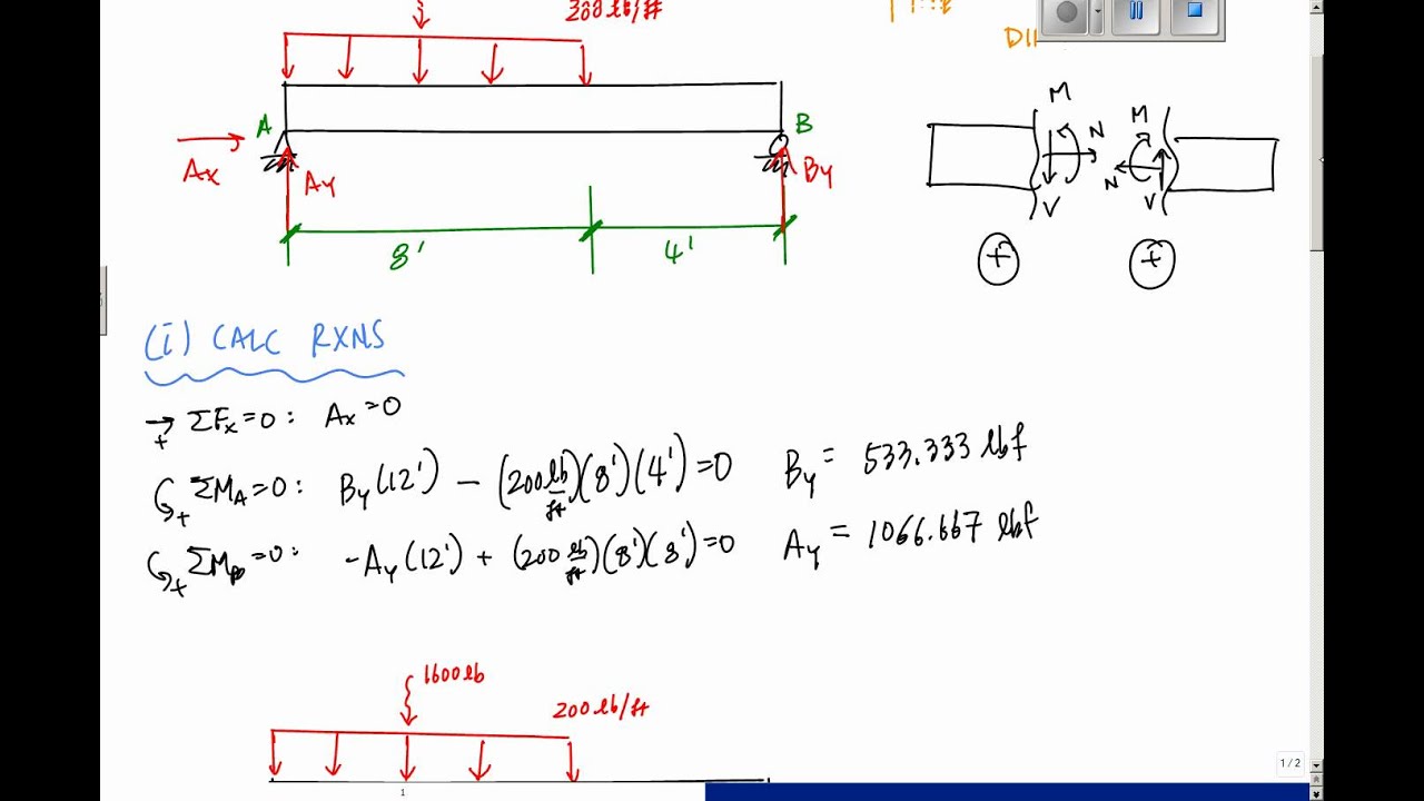
Solved Part A Select the correct shear diagram for the beam This problem has been solved! See the answer Show transcribed image text Expert Answer Transcribed image text: Part A Select the correct shear diagram for the beam (Figure 1) V 2wa o X 2a Figure < 1 of 1 > - Zwa 2wa . Za V wa a 2a -wa V wa x а 2a Part B. Select the correct moment diagram for the beam. M a O 2a X -wa? M wa? 2a X a -wa? Solved Choose the correct shear diagram for the beam. Follow Choose the correct moment diagram for the beam. Follow the sign convention. Consider the beam shown in (Figure 1). Choose the correct shear diagram for.1 answer · Top answer: Please ask your doubts in the... PDF CHAPTER 2 Shear Force And Bending Moment The beam shown below is supported by a pin at A and roller at B. Calculate the reactions at both supports due to the loading. 20 kN 40 kN 2 m 3 m 4 m A B EXAMPLE 1 Draw the free body diagram: By taking the moment at B, ΣM B = 0 RAy × 9 - 20 × 7 - 40 × 4 = 0 9R Ay = 140 + 160 R Ay = 33.3 kN ΣF y = 0 R+ By-20 40 = 0 R By= 20 + 40 -33.3
Select the correct shear diagram for the beam. (figure 1). PDF Problem 9 - Purdue University The beam is subject to the loading shown. 1. Choose the correct shear diagram from the column on the left. 2. Choose the correct moment diagram from the column on the right. Note: The moment diagrams on the right do not necessarily correspond to the diagrams on the left. Circle answers from following choices. Shear diagram Moment diagram 1) a) PDF Chapter 4 Shear and Moment In Beams - ncyu.edu.tw (1) Derive the shear and bending moment equations. And (2) draw the shear force and bending moment diagrams. Neglect the weight of the beam. The support reactions A and C have been computed, and their values are shown in Fig. (a). Solution Part 1 Due to the presence of the coupleC 0,We must analyze segments ABand BC separately. Shear and Moment Diagrams | Strength of Materials Review ... Shear and Moment Diagrams. Shear and Moment Diagrams. Consider a simple beam shown of length L that carries a uniform load of w (N/m) throughout its length and is held in equilibrium by reactions R 1 and R 2. Assume that the beam is cut at point C a distance of x from he left support and the portion of the beam to the right of C be removed. Solved w Jс В Select the correct shear diagram for the ... Expert Answer 100% (16 ratings) Transcribed image text: w Jс В Select the correct shear diagram for the beam.
PDF Shear Forces and Bending Moments in Beams A= Area of shear force diagram between A and B Concentrated loads Shear force slope (dV/dx) = 0 At load application V 1= -P Moment slope (dM/dx) = V (not valid at load application) Concentrated loads Moment slope (dM/dx) decreases by P M B- M A= Area of shear force diagram between A and B Concentrated Couples Bending moment and shear force in statically determinate ... The following statements are related to bending of beams: I The slope of the bending moment diagram is equal to the shear force. II The slope of the shear force diagram is equal to the load intensity. III The slope of the curvature is equal to the flexural rotation. IV The second derivative of the deflection is equal to the curvature. Calculating Shear Force Diagram | SkyCiv Engineering Calculating Shear Force Diagram - Step 2: Keep moving across the beam, stopping at every load that acts on the beam. When you get to a load, add to the Shear Force Diagram by the amount of the force. In this case we have come to a negative 20kN force, so we will minus 20kN from the existing 10kN. i.e. 10kN - 20kN = -10kN. Solved Part A Select the correct shear diagram for the ... Expert Answer 100% (31 ratings) Transcribed image text: Part A Select the correct shear diagram for the beam. (Figure 1) wa 2a -wa 2wa 2wa x. 2a -2wa wa -Part B Select the correct moment diagram for the beam. 2a 2a 2a 24 Previous question Next question
PDF Beam Design Formulas With Shear and Moment WITH SHEAR AND MOMENT DIAGRAMS American Forest & Paper Association w R V V 2 2 Shear M max Moment x DESIGN AID No. 6. AMERICAN WOOD COUNCIL The American Wood Council (AWC) is part of the wood products group of the ... Shear M 1 M max 3 8 x Figure 15 Beam Fixed at One End, Supported at Other-Uniformly Distributed Load Shear Force and Bending Moment Diagram for Simply ... To find out Shear Force, first we will calculate R a and R c.. Beam is simply supported ∑M a = ∑M c = 0.. Let us consider ∑M a = 0.. 6*4 - R c *8 = 0 (Clockwise bending moment will be positive and Anti-Clockwise will be negative). R c = 24/8. R c = 3. As we can see from the figure load is applied in the center, so both reaction will be same. PDF Chapter 2. Design of Beams - Flexure and Shear • A beam is a structural member that is subjected primarily to transverse loads and negligible axial loads. • The transverse loads cause internal shear forces and bending moments in the beams as shown in Figure 1 below. w P V(x) M(x) x w P V(x) M(x) x Figure 1. Internal shear force and bending moment diagrams for transversely loaded beams. Draw The Shear Diagram For The Beam Follow The Sign ... To calculate the shear forces of a beam follow the following simple steps. Follow the sign convention. Mechanics Of Materials Chapter 4 Shear And Moment In Beams Follow the sign convention. Draw the shear diagram for the beam follow the sign convention. 12 shear and moment functions. Draw the shear diagram for the beam. Figure 1 part b.
Laser Beam Shaping Overview | Edmund Optics
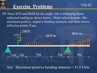
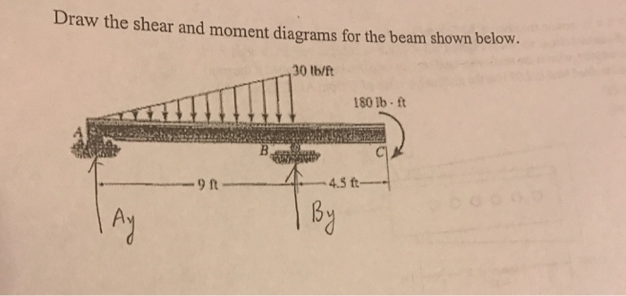
(Solved) - A steel beam is loaded as shown in the figure ... 1 Answer to Do it as soon as possible now please A steel beam is loaded as shown in the figure. The given loads are SERVICE loads and the beam weight is included in the DL. Determine the factored loads. Draw the shear force (v) diagram Draw the bending moment (M) diagram Design the beam and select a W-shape

What's the Difference Between Beam Diagrams? | Machine Design
Statics Final MC practice Flashcards - Quizlet In mechanics of materials, the bending stress of a beam in bending can be determined by the equation σ =My / I where expressed in terms of SI base units is the bending moment in Newton-meters (N -m), y is the distance from the neutral axis in meters (m ), and I is the moment of inertia in meters to the fourth power (m4 )
Operation of a thyristor surge suppressor crowbar type ...
Answered: Part A Draw the shear diagram for the… | bartleby Part A Draw the shear diagram for the beam. Follow the sign convention. (Figure 1) Click on "add vertical line off" to add discontinuity lines. Then click on "add segment" button to add functions between the lines. Note - Make sure you place only one vertical line at places that require a vertical line.

SciELO - Brasil - Concrete beam subjected to shear and ...
Q 1 The bending moment diagram of the beam shown in the ... Q 6 For the shear force diagram shown in given figure The loaded beam will be Q 7 Match List-I (Type and position of force on cantilever) with List-II (Shape of moment diagram for cantilever) and select the correct answer using the codes given below the lists:
Shear force and bending moment diagram
Shear Force & Bending Moment Diagram of Simply Supported Beam Bending Moment Diagram Simply Support Beam with UDL & Point Load Example. Draw shear force and bending moment diagram of simply supported beam carrying uniform distributed load and point loads. As shown in figure. Solution. First find reactions R1 and R2 of simply supported beam. Reactions will be equal. Since, beam is symmetrical.
Solved w Jс В Select the correct shear diagram for the ...
The Ultimate Guide to Shear and Moment Diagrams ... 4.0 Building Shear and Moment Diagrams. In the last section we worked out how to evaluate the internal shear force and bending moment at a discrete location using imaginary cuts. But to draw a shear force and bending moment diagram, we need to know how these values change across the structure.
1.10: Force Method of Analysis of Indeterminate Structures ...
Solved Part A Select the correct shear diagram for the ... Question: Part A Select the correct shear diagram for the beam (Figure 1) V WL * 5L 8 L WL 4 V WL 뿡 X ЗwL. 8 V WL 8 3L 8 WI V wL 8 3L 8 X Figure 3wL 8 Submit Request Answer Part B Select the correct moment diagram for the team This problem has been solved! See the answer Show transcribed image text Expert Answer 100% (5 ratings)
9363768c_CAS 90HD_DE_GB.indd
Select the correct shear diagram for the beam. (Figure 1 ... Select the correct shear diagram for the beam. (Figure 1) Shear force Shear force is the force in the beam acting perpendicular to its longitudinal axis. For design purposes, the beam's ability to...
Improved shadow correction for the marine optical buoy, MOBY
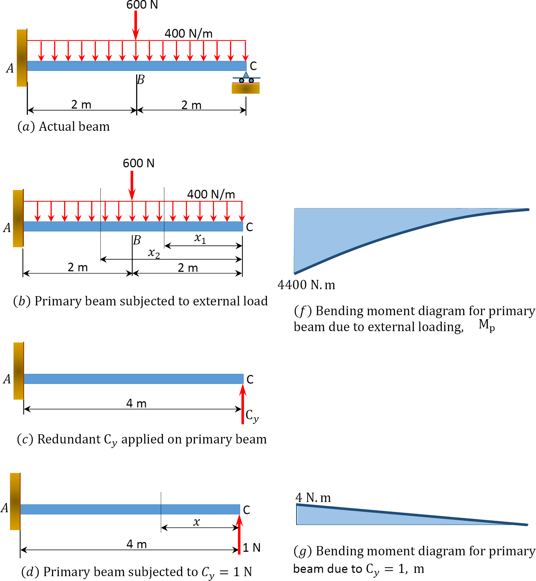
(Solved) - Determine the reactions and draw the shear and ... 1 Answer to Determine the reactions and draw the shear and bending moment diagrams for the beams shown in Figs. P13.1-P13.4 by using the method of consistent deformations. Select the reaction moment at the fixed support to be the redundant.

A 1 m-long beam has a load of 5 kN applied at its center and ...
Chapter 4 Bending Moment and Shear Force Diagram S K ... If the SF diagram for a beam is a triangle with length of the beam as its base, the beam is: [IAS-2007] (a) A cantilever with a concentrated load at its free end (b) A cantilever with udl over its whole span (c) Simply supported with a concentrated load at its mid-point (d) Simply supported with a udl over its whole span IAS-7.
329 6–1. Draw the shear and moment diagrams for the shaft ...
Answered: Draw the shear diagram for the beam.… | bartleby Draw the shear diagram for the beam. Follow the sign convention. (Figure 1) Click on "add vertical line off" to add discontinuity lines. Then click on "add segment" button to add functions between the lines. Note 1 - Make sure you place only one vertical line at places that require a vertical line.
Untitled
PDF CHAPTER 2 Shear Force And Bending Moment The beam shown below is supported by a pin at A and roller at B. Calculate the reactions at both supports due to the loading. 20 kN 40 kN 2 m 3 m 4 m A B EXAMPLE 1 Draw the free body diagram: By taking the moment at B, ΣM B = 0 RAy × 9 - 20 × 7 - 40 × 4 = 0 9R Ay = 140 + 160 R Ay = 33.3 kN ΣF y = 0 R+ By-20 40 = 0 R By= 20 + 40 -33.3
9363768c_CAS 90HD_DE_GB.indd
Solved Choose the correct shear diagram for the beam. Follow Choose the correct moment diagram for the beam. Follow the sign convention. Consider the beam shown in (Figure 1). Choose the correct shear diagram for.1 answer · Top answer: Please ask your doubts in the...

Combined fluorescence, optical diffraction tomography and ...
Solved Part A Select the correct shear diagram for the beam This problem has been solved! See the answer Show transcribed image text Expert Answer Transcribed image text: Part A Select the correct shear diagram for the beam (Figure 1) V 2wa o X 2a Figure < 1 of 1 > - Zwa 2wa . Za V wa a 2a -wa V wa x а 2a Part B. Select the correct moment diagram for the beam. M a O 2a X -wa? M wa? 2a X a -wa?

Shear Force Diagram - an overview | ScienceDirect Topics
Chapter 4-internal loadings developed in structural members
329 6–1. Draw the shear and moment diagrams for the shaft ...
Problem 9.1 Two beam segments, AC and CD, are connected ...

Solved w Jс В Select the correct shear diagram for the ...

Shear and moment diagram - Wikipedia

Why do we calculate STRESS, when we have FORCES?
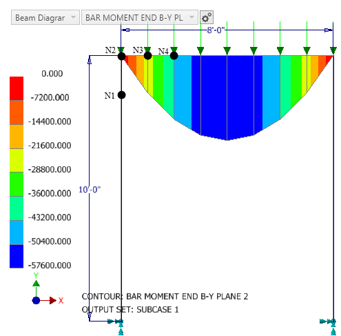
How to understand results in beam and bar elements in Nastran ...
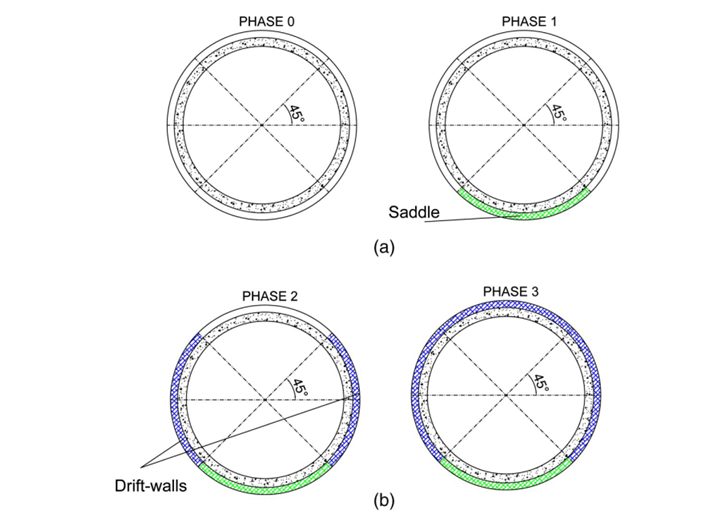
Blog | Modelling of the joints between segments in TBM tunnel ...

Shear Force Diagram - an overview | ScienceDirect Topics
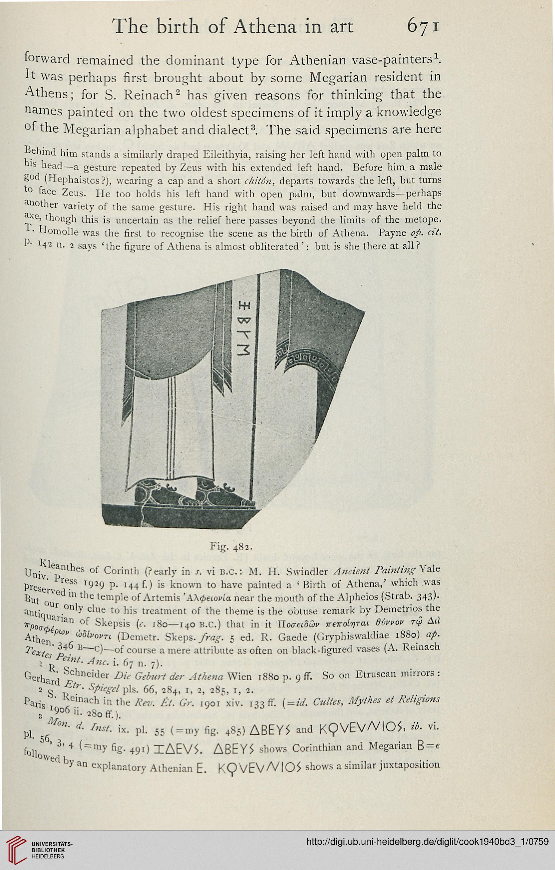
Cook, Arthur B.: Zeus: a study in ancient religion (Band 3,1 ...
Mechanics of Materials Chapter 4 Shear and Moment In Beams
Solved) - Draw the shear and moment diagrams for the beam ...

Beam Reactions and Diagrams – Strength of Materials ...
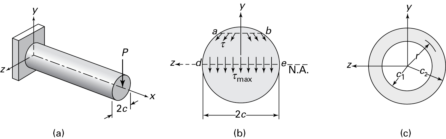
5.7 Normal and Shear Stresses | Bending of Beams | InformIT
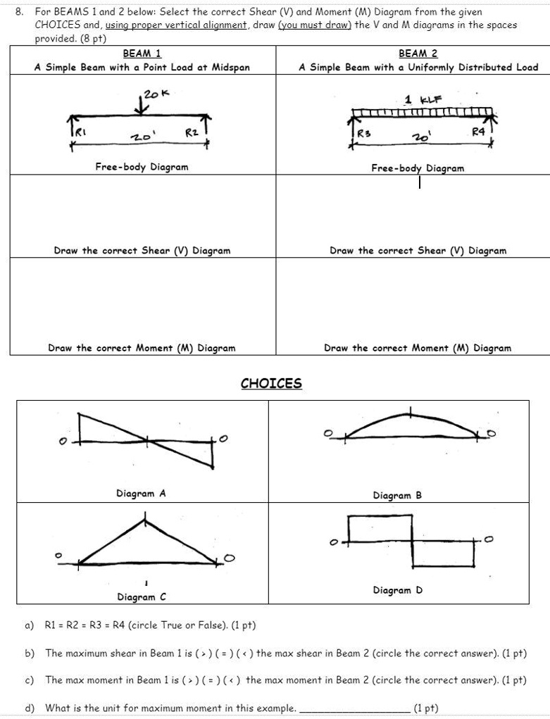
SOLVED:For BEAMS and 2 below: Select the correct Shear (V ...
![Solved] The correct shear force diagram for the cantilever ...](https://storage.googleapis.com/tb-img/production/18/01/AFCAT_1.PNG)
Solved] The correct shear force diagram for the cantilever ...
Drawing Shear and Moment Diagrams Example- Mechanics of Materials and Statics

Teaching Students How to Evaluate the Reasonableness of ...

Get Answer) - Select the correct shear and bending-moment ...
Mechanics of Materials Chapter 4 Shear and Moment In Beams

Bending moment and shear force diagram of a cantilever beam
0 Response to "36 select the correct shear diagram for the beam. (figure 1)"
Post a Comment