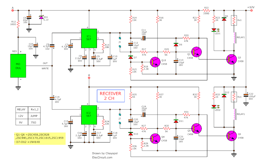
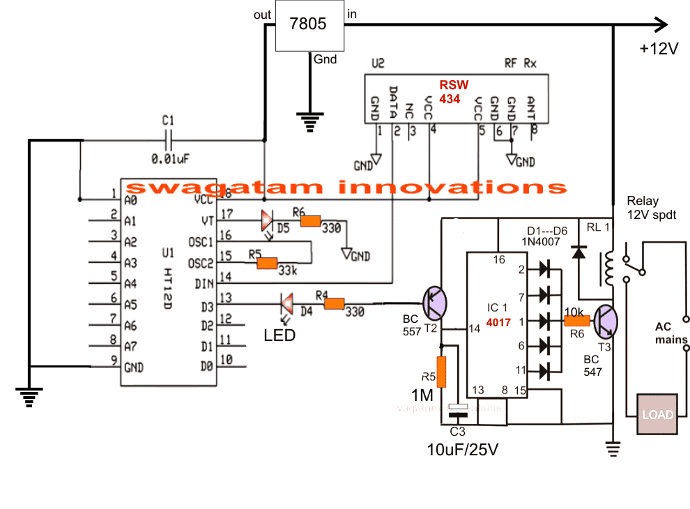
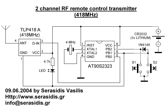
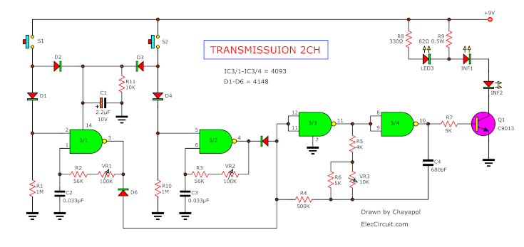
39 4 channel remote control circuit diagram
4 channel IR remote control circuit for home appliances ... The IR remote have unique hex codes for every button, it helps to uniquely identify witch button is pressed on the remote.So first we need to take the hex codes of button that we are going to use on the remote 4 channel rf remote control circuit diagram. control circuit diagram. how to decode 315mhz rf remote. rf based wireless remote control ... 433MHz 4-Channel Wireless RF Remote Control Kit - EEEShopBD Significant Notes. 4 Channel RF Remote Transmitter and Receiver allows to remotely control four appliances. RF Remote Control provides 4 momentary outputs that can be wired to relays and control home appliances, lights, motors, light dimmers, robotic devices, RC cars, computer, etc. RF transmitter provides up to 150m range.
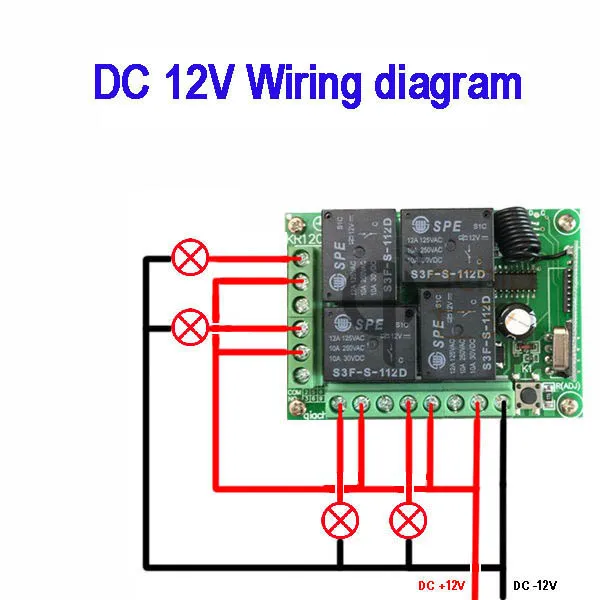
Qiachip KR1204 12V 4CHANNEL RECEIVER INSTRUCTION MANUAL Model:KR1204 WIRING DIAGRAM Function description and setting method * Note: All the following working modes need to be implemented with QIACHIP brand remote control (transmitter) and controller (receiver / wireless remote control switch). There is no guarantee that remote controls from other brands will work properly. This product requires a four-button remote control. Reset function ...

4 channel remote control circuit diagram
Remote Controlled Switch Circuit Diagram IR Remote Control Switch Circuit Diagram. In above IR Remote Control Light Switch, Output of TSOP1738 oscillates at the rate of 38KHz, which is applied to clock pulse of 4017. So we have connected a 1uF capacitor across the output of the TSOP so that this 38KHz pulse train is counted as one clock pulse to the IC 4017. 4 Channel Remote Control Circuit Diagram - IC 4017 + TSOP ... 4017 ic projects + TSOP Infrared IR REMOTE CONTROL 4 channel ( 3 ON & 1 OFF )Ide ini datang ketika saya harus bolak balik dalam menyalakan dan mematikan kip... Remote Control Circuits #'s-H - DiscoverCircuits.com 10-Channel IR Remote Control Receiver - it works with commercial iR remote transmitters and is a snack to build. The channels can be wired for momentary or toggle operation.__ SiliconChip. 12-channel Infrared Remote Control - it uses an infrared remote control unit and can switch 12 circuits, all either momentary or latched.__ SiliconChip
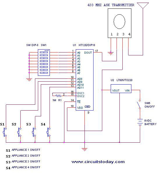
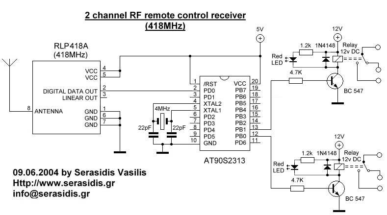
4 channel remote control circuit diagram. 433 MHz RF 8 Appliances Remote Control Circuit - Homemade ... The following example circuit illustrates the address pin configuration of the relevant Tx and Rx modules. Here we have employed a 4 channel remote module, however a single channel module could also be employed for getting the same results, just by modifying the indicated address pins of the units. The Receiver Circuit Four Channel Remote Control System | 4CH-RC Specifications. Radio frequency 310 Mhz. 2 or 4 channel. Programmable remotes. Each remote has 4 buttons, 2 buttons per actuator. 2 modes - sustaining (latching), or momentary. Requires 12VDC input (not included) 10 AMP fuse should be used on each channel to protect the remote system. Easy to wire actuators to 4 channel remote control system. RF remote control circuit - theoryCIRCUIT RF remote control circuit. RF remote control circuit designed with 434 MHz ASK (Amplitude shift keying) transmitter and receiver, Here IC HT12E act as encoder and IC HT12D act as decoder, this circuit is constructed with easy available components. This remote gives approximately 150 meter coverage by extending the ariel wire it can be increased ... Remote controlled appliance switch circuit Notes. Before wiring the circuit make sure that the carrier frequency of the TV remote you have is 38 KHz.For that wire the sensor part only ,point your remote to the TSOP1738 and press any switch.If out put of TSOP1738 goes low them ok, your remote is of 38Khz type.Nothing to worry almost all TV remote are of this type.
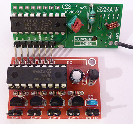
4-CH RF Remote Control - Electronics DIY Remote Control Dimensions: 58mm x 26mm x 13mm. (when antenna is not extended) 4-CH RF Remote Control. Having the ability to control various appliances inside or outside of your house wirelessly is a huge convenience, and can make your life much easier and fun. RF remote control provides long range of up to 200m / 650ft and it works even through ... 4 Channel RF Remote Controller - Electronics-Lab.com 4 Channel RF remote built using PT2262 and PT2272-M4 IC from Princeton technology. PT2262 used as Encoder (Transmitter) and PT2272-M4 Decoder (Receiver) ICs are heart of the project. The receiver provides 4 channel Momentary outputs. All outputs are TTL level can be interface with other circuits or relay board. 4 Channel Rc Transmitter And Receiver Circuit Diagram - U ... 1-48 of over 1000 results for. Detailed circuit schematic of the 2 4 ghz radio transmitter with scientific diagram sky403 4ghz schematics prints rc model fun 10 channel remote control switch homemade projects basic a system on chip cc2430 under other circuits 57344 next gr architecture receiver b. RF Transmitter and Receiver Circuit Diagram As said they have 4-data bit and 8-addresss bit, these 8 address bits has to be set same on both the encoder and decoder to make them work as a pair. Circuit Diagram of RF Transmitter and Receiver: The complete circuit Diagram including the Transmitter and Receiver part for this project is shown in the images below.
5 Channel IR Remote Control System using Microcontroller 5 Channel IR Remote Control Circuit Design: The transmitter circuit is made up of three ICs: an Atmel89C51 microcontroller, an HT12E encoder, and a 555 timer. The microcontroller interfacing is the initial step in the design process. A five-item DIP switch is connected to the microcontroller's port P1 on the input side. 4 channel infrared remote relays - Electronics-Lab.com Description. 4 Channel Infrared (IR) Remote controller is using HT12A and HT12D encoder / decoder chips from Holtek. Features. Supply - Transmitter : 3 to 5 VDC, 5 V @ 20 mA & Receiver : 5 VDC @ 200 mA 2.4 GHz 10 Channel Remote Control Switch - Homemade ... If you press the same button on remote again, it will turn OFF the output 1 at receiver. • It applies for all the buttons and 10 outputs. • Turn off the remote after use. If you have any further questions regarding the above discussed 2.4 GHz 10 channel remote control switch, please express them in the comment section. Remote Control Switch Circuit | IR Remote Control ON OFF ... Remote Controlled Switch This is the very simple circuit diagram of the IR remote control switch. We use the normal switch in our daily life and after a long time used to these switching system we can no more interested in that. This is a good solution for a unique and so interesting idea to wireless switching system to control the home appliance.
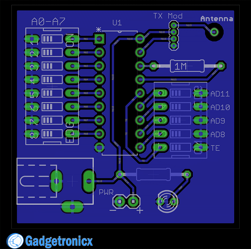
Making a 4 channel RF remote ( PCB design included ... Making a 4 channel RF remote ( PCB design included) Frank Donald August 14, 2017 14 Comments. ... This is because RF/ Wireless remote control circuits won't work as expected always. There are number of things that could go wrong with it, I have finally cracked making a DIY remote control which am gonna share with you all. ... But as far as I ...
Simple 4-channel ON-OFF remote control - DANYK.CZ Simple 4-channel ON-OFF remote control. This device is good for switching on and off up to 4 independent appliances by remote control. Pressing buttons 1, 2, 3 or 4 turns the corresponding output on, pressing it again turns it off. The remote control operates on the infrared principle, with a range of up to 50m.
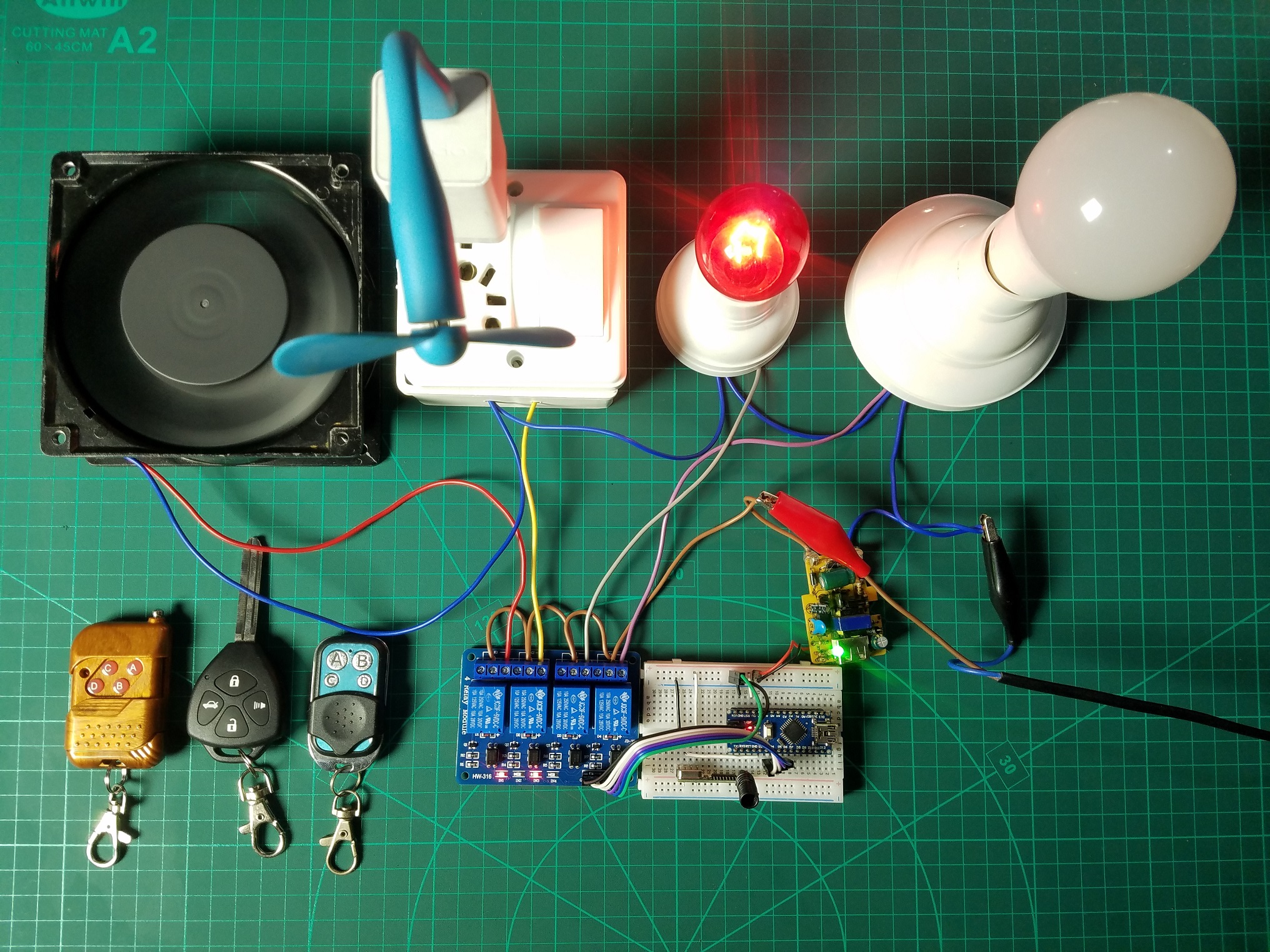
RF Remote Control For Home Appliances - Arduino Project Hub 4 channel rf remote control circuit diagram. control circuit diagram. how to decode 315mhz rf remote. rf based wireless remote control. rf remote control circuit for home appliances. rf remote control for home appliances project report. rf remote control kit. rf remote control switch circuit diagram. simple rf remote control circuit.

Long Range 3 Channel Remote Control Switch..Remote Control Switch Circuit For ON/OFF Light And Fan..
4 CHANNEL RF REMOTE CONTROLLER - BuildCircuit.COM 4 CHANNEL RF REMOTE CONTROLLER - BuildCircuit.COM. Post navigation. Previous Post PWM SOLENOID AND VALVE DRIVER USING DRV103. Next Post HEAT ACTIVATED COOLING FAN CONTROLLER.
4 Channel Remote Control and Receiver - Custom Electronics ... Home Shop Cyber Circuits 4 Channel Remote Control and Receiver- ... The receiver takes a 12V 200mA supply, and will control the relays which are rated for 10A at 12V DC or 5A at 220V AC. The keyfob transmitter comes with battery included and is ready to go! Weight: 0.1 kg: Dimensions:
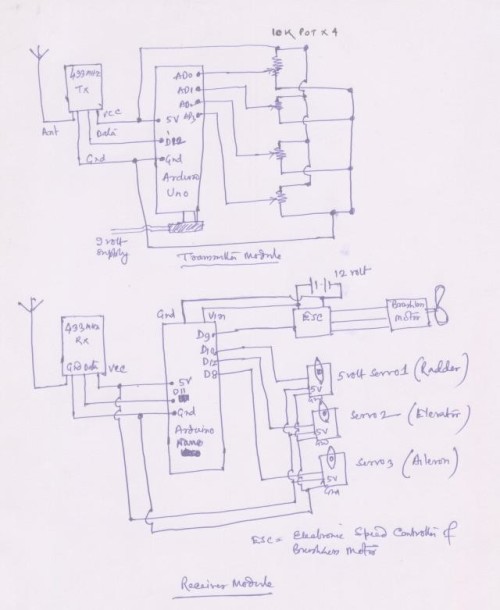
How to Build a Remote Control Home Automation ... - Maker Pro By operating a specific remote switch on the TX, the load can be turned on/off remotely via wireless technology. The circuit uses a radio module to make a wireless remote control that can be used to drive o / p from a distance. As the name implies, the RF module uses RF signals to send signals at a specific frequency and baud rate.
851067 12V 4 Channel Wireless Remote Control Module User ... Universal 4 Channel Remote Control Part number 851067 Kit contents: -Key FOB -Power Power module -Velcro -3m 3m double sided tape Step 1 Find a suitable place in the engine compartment close to the battery to mount the control module. Step 2 Once you have mounted the control module run your power and ground wires to the control module.
4 Channel Wireless Four button RF remote control ... The 4 Channel Wireless Four Button RF Remote Control Transmitter Receiver Module with Non-Locking mode can be composed of a fixed code four radio receiver circuits, remote control of four four-bit data output code corresponding to the module, you can easily make up a wireless remote control receiver circuit.. They are widely applied in the majority home electronics enthusiasts, industrial ...
Remote Control Circuits #'s-H - DiscoverCircuits.com 10-Channel IR Remote Control Receiver - it works with commercial iR remote transmitters and is a snack to build. The channels can be wired for momentary or toggle operation.__ SiliconChip. 12-channel Infrared Remote Control - it uses an infrared remote control unit and can switch 12 circuits, all either momentary or latched.__ SiliconChip
4 Channel Remote Control Circuit Diagram - IC 4017 + TSOP ... 4017 ic projects + TSOP Infrared IR REMOTE CONTROL 4 channel ( 3 ON & 1 OFF )Ide ini datang ketika saya harus bolak balik dalam menyalakan dan mematikan kip...
Remote Controlled Switch Circuit Diagram IR Remote Control Switch Circuit Diagram. In above IR Remote Control Light Switch, Output of TSOP1738 oscillates at the rate of 38KHz, which is applied to clock pulse of 4017. So we have connected a 1uF capacitor across the output of the TSOP so that this 38KHz pulse train is counted as one clock pulse to the IC 4017.










0 Response to "39 4 channel remote control circuit diagram"
Post a Comment