38 Log Splitter Hydraulic Circuit Diagram
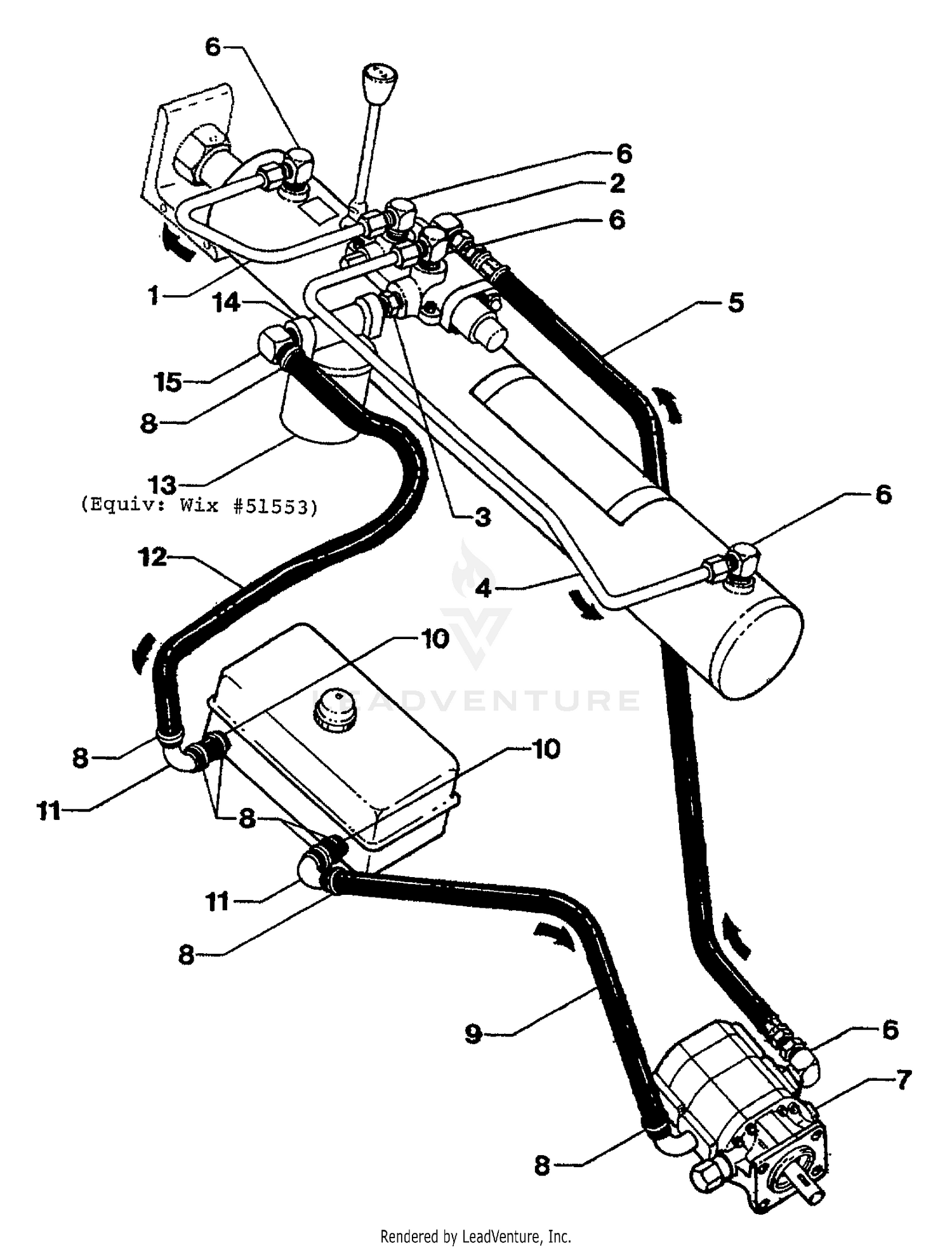
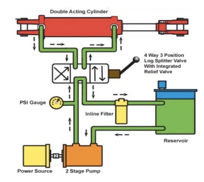
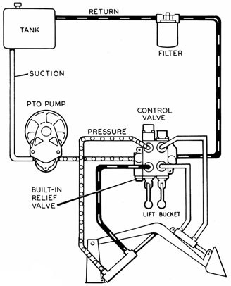
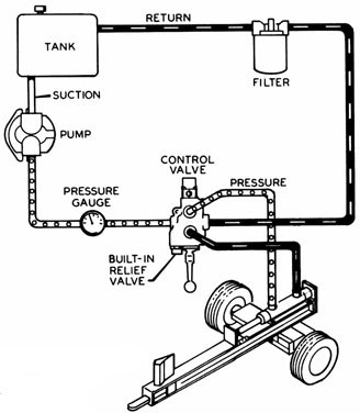
PDF Parts Needed for Building a Log / Wood Splitter Hydraulic Oil Reservoir Log Splitter Valve Auto Cycle Valve . Open Center hydraulic Valve: There are two basic valve systems used on log splitters: They come with different options . 1-Log splitter valve - You have to hold the valve lever on the splitting stroke & on the return stroke, there is a detent to Log Splitter Hydraulics and How It Works - Cylinder ... The Log Splitter Hydraulic Circuit. Most log splitters use a hydraulic cylinder ( like these) to push a cut piece of log into a sharpened wedge, which splits it. The cylinder is driven by hydraulic oil, under pressure, produced by a hydraulic pump. An engine, or electric motor, drives the pump shaft, and supplies the power for the system.
PDF 1500W ELECTRIC 4 TON LOG SPLITTER - Free Instruction Manuals to ensure the log splitter works under pressure no more than is listed in the specifications. The setting was made by a qualified mechanic with professional instruments. Unauthorised resetting will reduce the performance of the hydraulic pump or RESULT IN SERIOUS INJURY AS WELL AS DAMAGE TO THE MACHINE. WIRING DIAGRAM HYDRAULIC DIAGRAM

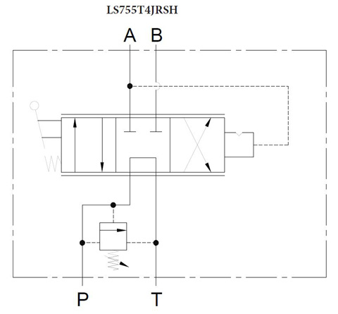
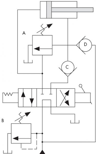
Log splitter hydraulic circuit diagram
How to Troubleshoot a Log Splitter Detent Valve - Synonym 1 Find the diagram. Find the diagram of the detent valve set up. There will be input valves for the pressurized and un-pressurized hose connections, and the diagram will show you which ones go on which side of the detent valve and in what order. If the hydraulic hoses are hooked up incorrectly, then the valve won't be able to function properly. Image result for log splitter hydraulic circuit diagram ... Sep 27, 2016 - Image result for log splitter hydraulic circuit diagram EP0718078B1 - Hydraulic circuit for a hydraulic log ... Fig. 2 is a side schematic diagram of the log splitter shown in Fig. 1 Fig. 3 is a cross sectional side elevational view of the hydraulic control valve, cylinder and ram of the present invention. Fig. 4 is an enlarged fragmentary cross sectional View of the control valve of Fig. 3 in which the valve is in a neutral position.
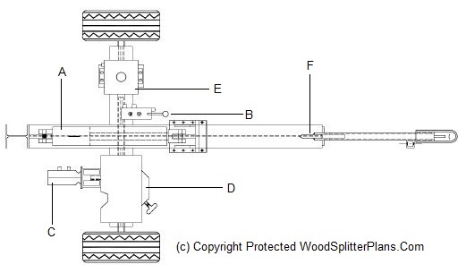
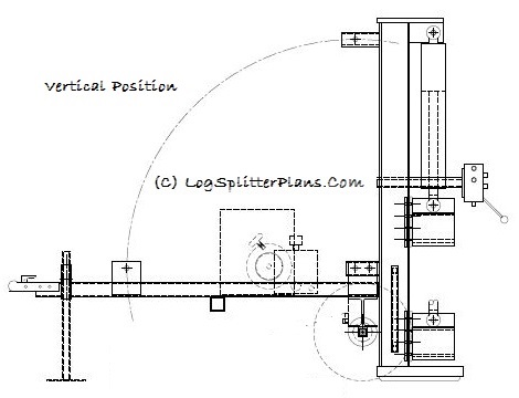
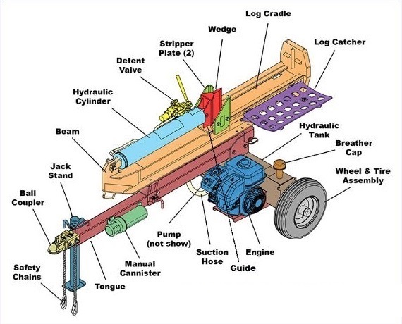
Log splitter hydraulic circuit diagram. PDF Log Splitter - Oregon Products Page 5 • NEVER use this log splitter for any other purposes than splitting wood. It is designed for this use only. Any other use can cause serious injury or death. • BEFORE operating this log splitter, make sure that you wear safety gear such as goggles or safety glasses, steel toed shoes and tight fitting gloves (without loose cuffs or draw strings). Log Splitter Hydraulic Pump Displacement Calculator A hydraulic pump produces liquid movement or the flow necessary to develop pressure, a function of resistance to fluid flow in the system. non-positive-displacement. Most pumps used in hydraulic systems are positive-displacement. In a positive-displacement pump, slippage is negligible compared to the pump's volumetric output flow. PDF 7 TON Electric LOG SPLITTER INSTRUCTION MANUAL Freeing a jammed log Replacing hydraulic oil Sharpening wedge ... Check that the electric circuit is adequately protected and that it corresponds with the power, voltage and frequency of the motor, check that there is a ground connection, and a regulation ... LOG SPLITTER. you. Hydraulic Wood Splitter Components The log splitter changes all of that! A log splitter is a machine with several components that make short order work of splitting firewood quickly and with much less effort. Before you shell a whole bunch of cash to buy or build a log splitter, lets review the wood splitter hydraulic components that make up this wood chopping machine.
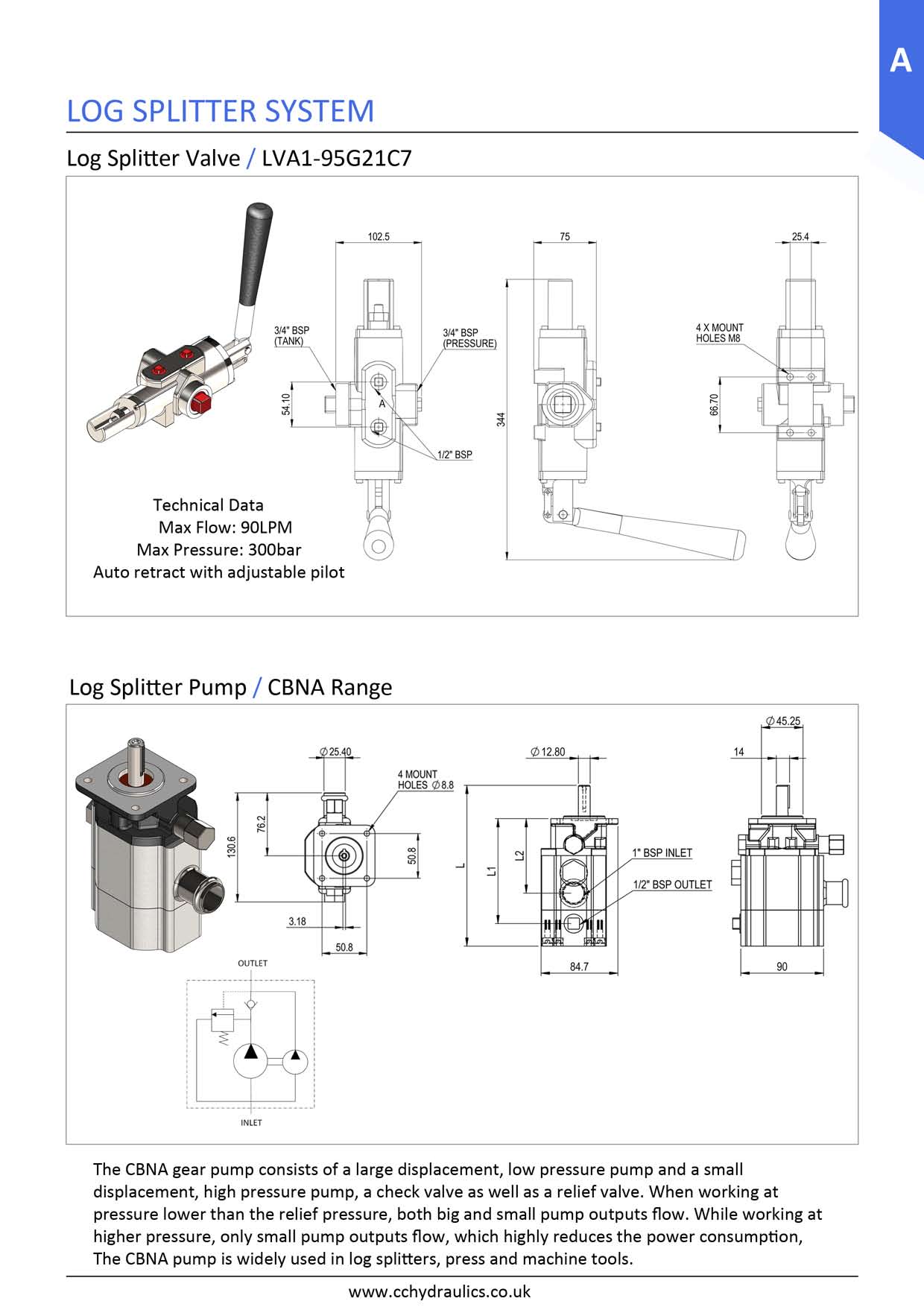
Huskee Log Splitter Parts Diagram | Automotive Parts ... Description : Speeco S390406Sc Log Splitter Valve - Omni Mfg Llc with regard to Huskee Log Splitter Parts Diagram, image size 500 X 380 px, and to view image details please click the image. Here is a picture gallery about huskee log splitter parts diagram complete with the description of the image, please find the image you need. PDF Directional control valve - Log splitter - hydraulic-vlv.com Directional control valve - Log splitter Model P81 ... 1 0 2 Hydraulic scheme for P81 A2 S10 2/7 Sep 2013. Port type (S - UN-UNF, G - BSP, N-NPTF) Spool detent - detent with hydraulic release (70 to 140 bar) Spool type (A) Directional control valve (80 l/min) Order Code: P81 A 2 G 12 Didier Log Splitter Parts Diagram - The Beyond Information Didier log splitter parts results for didier log splitter parts filter by: We hope it helps solve your problem. Log splitter replacement parts refine search. 1981 kz650 wiring diagram, carprog opel ecu manual, 1967 pontiac gto le mans tempest wiring diagram, the lawman s second. If you have a leaky hydraulic hose or broken cylinder, the power ... DR POWER Ton Electric log Splitter Instructions - Manuals+ 6 Parts Lists, Schematic Diagrams And Warranty. 6.1 Parts List - DR 5-TON ELECTRIC LOG SPLITTER. 6.2 Schematic ... Never run the Log Splitter unless the hydraulic fluid tank is at the proper level. Grasp the log on the sides near the middle of the block as you place the log on the Log Splitter.
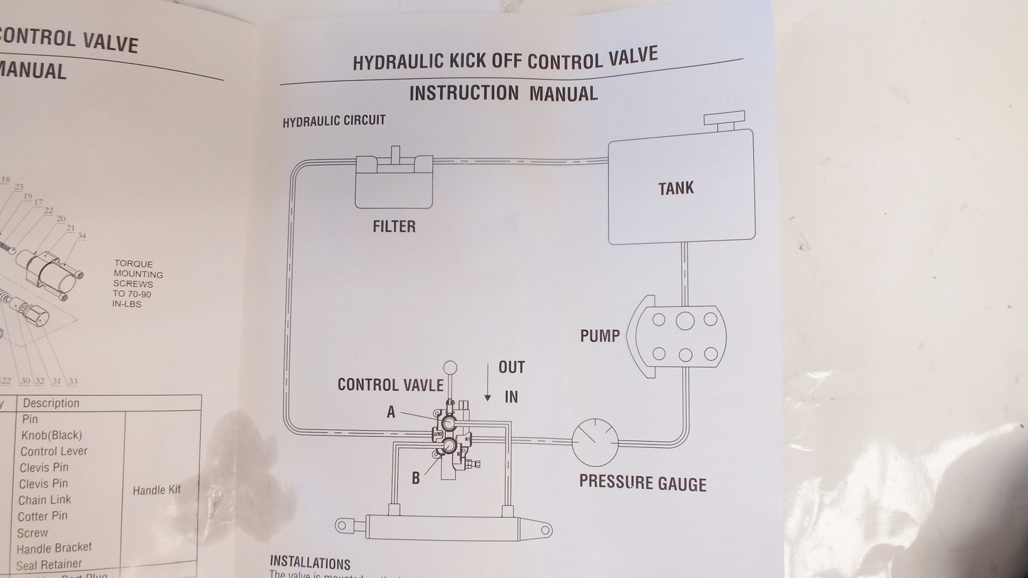
PDF 25 TON LOG SPLITTER - Tractor Supply Company ONLY operate the log splitter from the operator zone as shown in the diagram. Operating the log splitter in another location can result in serious injury or death. • ALWAYS chock the wheels to prevent movement of the log splitter while in operation. • KNOW how to stop the log splitter and disengage the controls before operating it. PDF Vertical/Horizontal Log Splitters 28 Ton Model Page 5 • NEVER use this log splitter for any other purposes than splitting wood.It is designed for this use only.Any other use can cause serious injury or death. • BEFORE operating this log splitter, make sure that you wear safety gear such as goggles or safety glasses, steel toed shoes and tight fitting gloves (without loose cuffs or draw strings). PDF Hydraulic Kick Off Control Valve Instruction Manual Hydraulic hoses are hooked up incorrectly. Find the diagram of the detent valve set up. There will be input valves for the pressurized and un-pressurized hose connections, and the diagram will show you which ones go on which side of the detent valve and in what order. Check for leaks. If the hoses aren't connected completely Circuit idea: two-speed log splitter | Power & Motion The circuit provides high extension speed until the cylinder meets resistance and then automatically produces higher force at lower speed until the log splits. Referring to the schematic, with the directional valve shifted for cylinder extension, pressurized fluid flows into the cap end of the cylinder. Fluid flowing from the rod end is blocked ...
PDF Gas Log Splitter - YARDMAX® Gas Log Splitter Operator's Manual ... Assembly 12 Parts Diagram 25 ... Pay attention to all cautions and warnings. This unit is a gasoline engine driven hydraulic log splitter. It is designed to split wood logs for use as firewood for a stove or fireplace. This log splitter will only split logs lengthwise with the grain.
PDF Owner's Manual - Log Splitter Plans The hydraulic system of your log splitter requires careful inspection along with the mechanical parts. Be sure to replace frayed, kinked, cracked or otherwise damaged hydraulic hose and components. ... STEP 2: Attach the tongue (3) to the tank/axle (2) as shown in the diagram using the two 1/2 in. NC x 4-1/2 in. hex cap screws (75), 1/2 in.
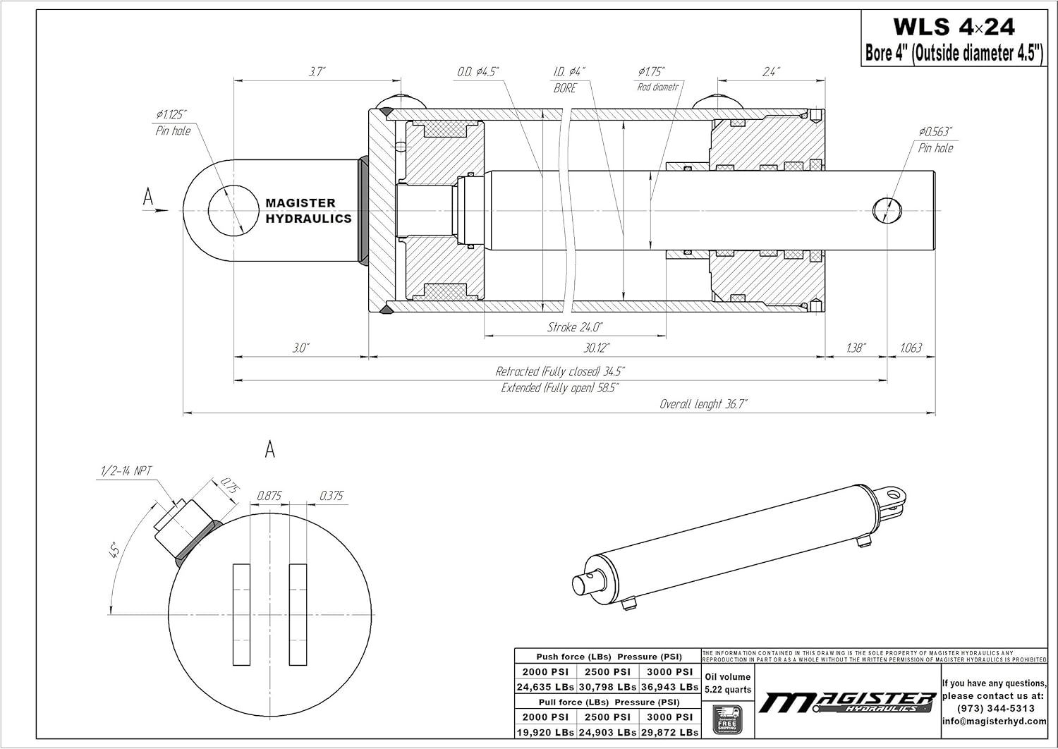
Log Splitter Parts Replacement Guide - Cylinder Services Inc Often a larger tonnage no-brand splitter may look very attractive at first, but the parts may be miss-matched, or of poor quality. Determine your replacement log splitter parts needs by using calculators. Give Don's Hydraulic Cheat Sheet a try. Just change the fields marked "Bore, Rod, Stroke, Pressure and GMP" to calculate your force and ...
Speeco 25- & 28-Ton Log Splitter Parts Diagram - Foards Foards Parts Plus offers a complete collection of replacement parts for Speeco 25- and 28-ton log splitters (597477, 597478). Explore the diagram online.
How Log Splitters Work - Log Splitters | HowStuffWorks An engine, normally a small four-stroke gasoline engine, provides the power for the system.The engine is attached to a hydraulic oil pump. The hydraulic oil pump creates a stream of high-pressure oil, which runs to a valve.; The valve lets the operator actuate the hydraulic cylinder to split a log.; There is also a tank to hold the hydraulic oil that feeds the pump and usually a filter to keep ...
Hydraulic schematic | Hydraulic circuits | Mechanical ... "A hydraulic circuit is a system comprising an interconnected set of discrete components that transport liquid. The purpose of this system may be to control where fluid flows (as in a network of tubes of coolant in a thermodynamic system) or to control fluid pressure (as in hydraulic amplifiers).
Hydraulics Systems Diagrams and Formulas - Cross MFG The diagram shows a winch powered by a hydraulic motor. The directional control valve with built-in relief features optional flow control to control the speed of the winch . The hydraulic pump and motor must be matched to the torque requirements of the winch. Logsplitter.
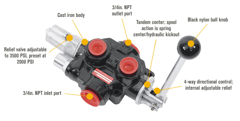
Log Splitter Detent Valve Diagram The USA's most popular log splitter valve. Specified by Spring centered in one direction, and pressure released detent in the other direction. Automatically. The detent valve in a log splitter is the central assembly where the the diagram will show you which ones go on which side of the detent valve.
PDF Electric Log Splitter Freeing a Jammed Log 9 Replacing Hydraulic Oil 10 Sharpening the Wedge 10 Troubleshooting 11 Wiring Diagram 11 Plumbing Diagram 11 ... Your log splitter will do a better and safer job at its design ... Check that the electric circuit is grounded, adequately protected, and that it corresponds with the power, voltage, and frequency of ...
Basics of a Hydraulic Log Splitter - YouTube This video explains the basics of how a hydraulic log splitter works. It also offers tips for use. This model is available at Agri Supply.Shop at one of our ...
Hydraulic circuit for a hydraulic log splitter - CLARKE ... Fig. 2 is a side schematic diagram of the log splitter shown in Fig. 1 Fig. 3 is a cross sectional side elevational view of the hydraulic control valve, cylinder and ram of the present invention. Fig. 4 is an enlarged fragmentary cross sectional View of the control valve of Fig. 3 in which the valve is in a neutral position.
EP0718078B1 - Hydraulic circuit for a hydraulic log ... Fig. 2 is a side schematic diagram of the log splitter shown in Fig. 1 Fig. 3 is a cross sectional side elevational view of the hydraulic control valve, cylinder and ram of the present invention. Fig. 4 is an enlarged fragmentary cross sectional View of the control valve of Fig. 3 in which the valve is in a neutral position.
Image result for log splitter hydraulic circuit diagram ... Sep 27, 2016 - Image result for log splitter hydraulic circuit diagram
How to Troubleshoot a Log Splitter Detent Valve - Synonym 1 Find the diagram. Find the diagram of the detent valve set up. There will be input valves for the pressurized and un-pressurized hose connections, and the diagram will show you which ones go on which side of the detent valve and in what order. If the hydraulic hoses are hooked up incorrectly, then the valve won't be able to function properly.













0 Response to "38 Log Splitter Hydraulic Circuit Diagram"
Post a Comment