35 4-20ma pressure transducer wiring diagram
A wiring diagram is a streamlined standard pictorial depiction of an electric circuit. 2 wire pressure transducer wiring diagram 4 20ma transmitter circuit diagram awesome 3 wire pressure transducer wiring diagram. All devices in a 4 20 ma current loop need to be supplied power from somewhere in order to function. The SI-300 4-20mA/Voltage Pressure Transducer, also called pressure transmitter 4-20mA. It is a pressure sensor with 4-20ma/Voltage output. 4-20mA Pressure Transducer can be OEM as differential pressure, explosion-proof, or sanitary, just as you need.Ideal for OEMs, process applications, water processing, and industrial pressure applications.
converters (current-to-pressure transducers) are available to convert the 4-20mA control loops to common pneumatic ranges, such as 3-15psi, 1-18psi, 3-27psi, and 6-30psi. In two-wire 4-20mA control loops, we use 2-wire transmitters to convert various process signals representing flow, speed, position, level, temperature,
4-20ma pressure transducer wiring diagram
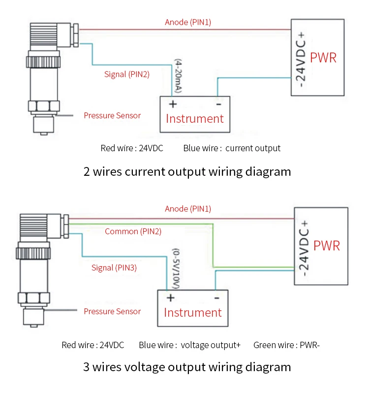
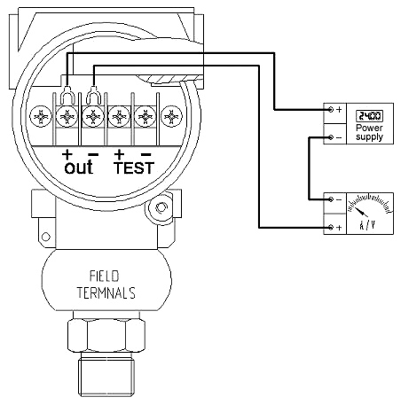
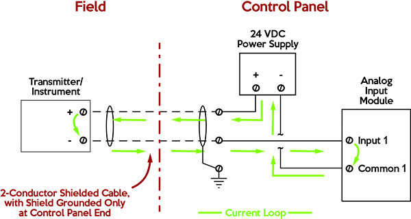
A) If the 4-20mA Input Device includes an Internal Sensor Power Supply and has 2 input connections: Connect Positive (+) Input connection to Positive (+) Pressure Transmitter connection; Connect Negative (-) Input connection to Negative (-) Pressure Transmitter connection; B) If the 4-20mA Input Device requires an External Sensor Power Supply and has 2 input connections: For 4-20mA loops with 2-wire transmitters, common power supply voltages are 36VDC, 24VDC, 15VDC and 12VDC. Current loops using 3-wire transmitters can have either AC or DC power supplies. The most common AC power supply is the 24 VAC control transformer. Be sure to check your transmitter's installation manual for the proper voltage requirements. Get 4 20ma Pressure Transducer Wiring Diagram Sample. Assortment of 4 20ma pressure transducer wiring diagram. A wiring diagram is a streamlined standard photographic depiction of an electrical circuit. It shows the elements of the circuit as streamlined shapes, as well as the power and signal connections in between the gadgets.
4-20ma pressure transducer wiring diagram. 4 20Ma Pressure Transducer Wiring Diagram. Print the wiring diagram off and use highlighters to trace the routine. When you employ your finger or perhaps the actual circuit together with your eyes, it may be easy to mistrace the circuit. A single trick that We use is to print out exactly the same wiring plan off twice. See Figures 21, 22, 23, and 24 for examples of 2-wire, 3-wire, and 4-wire instruments. An analog signal range that has a non-zero low-end, such as 3 to 15 PSIG or 4 to 20 mA, is known as a "live-zero"range because the low end is not dead, but has some pressure, voltage, or 3 wire pressure transducer wiring diagram - 4 20ma Pressure Transducer Wiring Diagram Elegant Viatran Model Rm570 Br Pressure Transmitter. File Type: JPG. Source: kmestc.com. Variety of 3 wire pressure transducer wiring diagram. Click on the image to enlarge, and then save it to your computer by right clicking on the image. Figure 1. Typical wiring configuration for millivolt output transducer Figure 3. Typical wiring configuration for current output transducer Figure 4. Multi-instrument 4-20mA current loop (panel meters, chart recorder, computers, etc.) Minimum voltage req'd = (0.20 Amps)(R LINE + R LOAD) + Vs TRANSDUCER Figure 5.
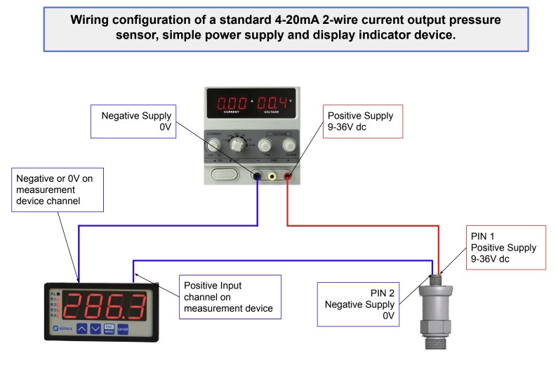
4 20ma Pressure Transducer Wiring Diagram Download. 4 20ma pressure transducer wiring diagram - A Novice s Overview of Circuit Diagrams An initial appearance at a circuit representation could be complicated, but if you can read a subway map, you could check out schematics. The function is the exact same: receiving from point A to direct B.… 4-20mA Help 2 wire 4-20ma pressure transmitter wiring configuration. The diagram below below shows a simple wiring configuration for current loop pressure transmitter. It is assumed that the measurement device includes a sufficient load resistance for measuring a current loop. Trying to find information regarding pressure transducer wiring diagram. Pressure sensor specifier select your pressure sensor requirements. While reviewing the wiring diagram on some pressure transmitters 2 wire 4 20ma output direct wire im about to buy i noticed a slight inconsistency with the wiring in the ni9203 user manual. 4-20mA (2 wire loop powered)* +Temp -Press +Press -Temp NOTICE FOR HAZARDOUS AREA SENSORS (AST46PT) - Refer to operating instructions for installation information. * For units with loop-powered 4-20mA output, the pressure loop must be powered or the temperature output will not operate.
A Circuit Diagram Of The Digital Pressure Signal Conditioner Max1459 4 20ma Cur Transmitter Under Circuits 58756 Next Gr. Op90 4 Ma To 20 Cur Loop Transmitter Electronic Circuit Diagram. Planet Analog Signal Chain Basics 119 2 Wire 4 20 Ma Sensor Transmitter Measurement. Design Trade Offs For Loop Powered Transmitters Analog Devices. Industrial transmitters are available for monitoring many parameters these including pressure, temperature and flow etc. Gas detectors / transmitters offer 4-20mA outputs, where 4 mA equates to a zero reading and 20 mA equates a full scale reading of the calibrated range.. This signal is sent to a remotely located control panel. Pressure sensor link, https://www.ato.com/pressure-sensorThe video shows the connection of the 2-wire ATO pressure sensor/transducer. The ATO pressure sensor... The 4-20 mA current loop is the dominant standard in many industries. It is the simplest option to connect and configure. It uses less wiring and connections than other signals, greatly reducing initial setup costs. Better for traveling long distances, as current does not degrade over long connections like voltage.
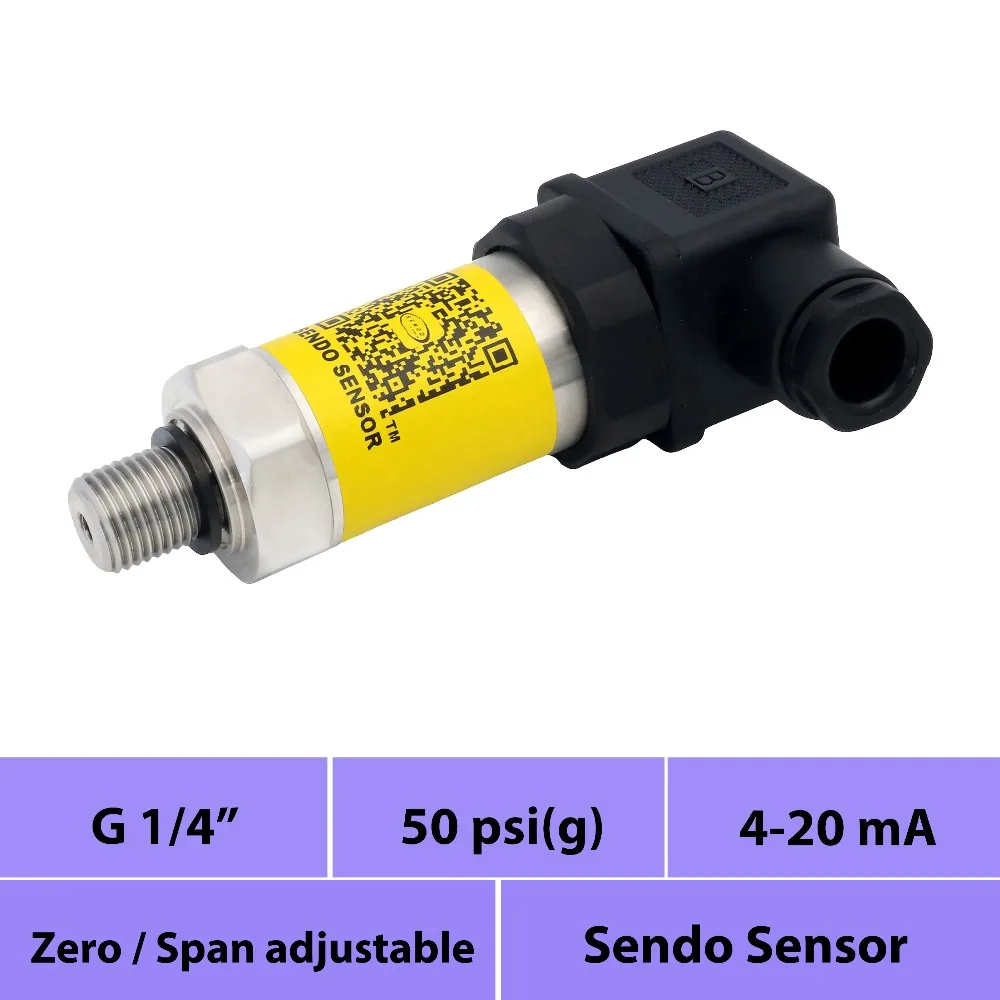
4 20mA pressure sensor transducer, pressure 50psi vented ...
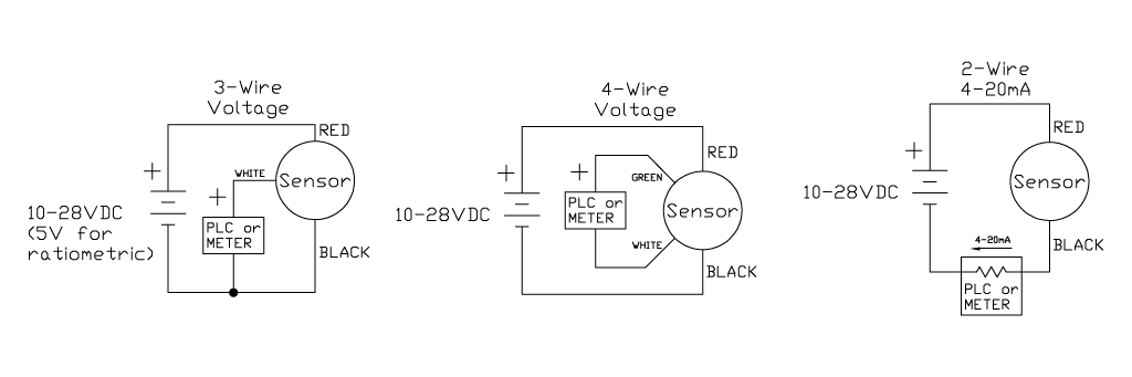
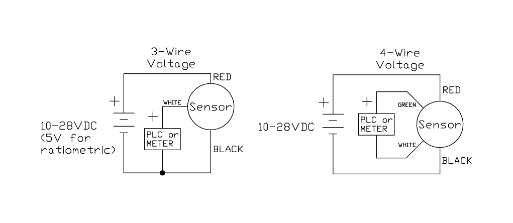
Today's electronic process transmitters - pressure, temperature, flow and level are connected in different wire types or configurations. These connection methods are of great concern to the instrument engineer/technician. The 2 - Wire, 3 - Wire and 4 - Wire types are often used to describe the method of connection of electronic transmitters.

5 to 1600PSI Pressure Transducer Sensor Output 0.5-4.5V 4 ...
The 4 20ma analogue signal is by far the most commonly used in industrial applications. 4 20ma transmitter wiring diagram. Get 4 20ma pressure transducer wiring diagram sample collections of 3 wire pressure transducer wiring diagram luxury great 3 wire sensor. January 9 2020 by larry a. 4 20 Ma Transmitter Wiring Types 2 Wire 3 Wire 4 Wire.

Example 4-20mA thermistor transmitter wiring diagram ...
3 Wire Pressure Transmitter Wiring Diagram. Pressure transducers installation and use 4 20ma transmitter wiring 3 wire technology in sensors china low range sensor electrical connections guide 0 40 mpa 5 volt into the plc dc4 input detachable rsinstruments danfoss mbs 3000. Difference Of 4 20 Ma In 2 Wire And 3 Technology Pressure Sensors Wika ...

Need more current than 4 mA in 4/20mA loop current ...
3 Wire Pressure Transmitter Wiring Diagram. Pressure transducers installation and use 3 wire 4 20ma transmitter wiring difference of 20 ma in 2 technology sensors wika blog electrical connections guide dylix corporation types china fst800 1100 25bar 24v 5v dc small low range sensor rsinstruments model name number rsigp 1007 rs 1950 piece id ...
4 20Ma Pressure Transducer Wiring Diagram Database
2 wire for current transducers and 3 wire for voltage transducers. 4 wire pressure transducer wiring diagram. Next disconnect the wire form the transducer that is connected to the control circuit and place the lead form the digital milliamp meter to the black wire. Here are links to the user manuals for the sensors. Posted by tracy molnar on tue.
2 Wires 4-20ma 0-10v Refrigeration Air Compressor Air ...
In this video, we show you how to wire a pressure transducer two ways: 2 wire for current transducers and 3 wire for voltage transducers.To learn more, visit...
4 20ma Circuit Diagram - Wiring Diagram Networks
Wiring Diagram Images Detail: Name: 4 20ma pressure transducer wiring diagram - 4 20ma Transmitter Circuit Diagram Best 3 Wire Pressure Transducer Wiring Diagram. File Type: JPG. Source: golfinamigos.com. Size: 101.01 KB. Dimension: 985 x 729.

Pressure Transmitter Pressure Transducer 4-20ma | Kaidi
Pressure sensors with a 0.5…4.5V output for industrial 3-wires current loop (4…20mA) applications Nov. 2004 4/9 Analog-Digital Micromechanical Sensor Systems Description of the application Pressure transmitter SM5812's output signal of 0.5V…4.5V is to be converted into an output current signal of 4…20mA as a 3-wire version.

Wiring diagram for Rosemount 3051SMV converted into ...
OUTPUT: 4 to 20 mA (2-wire) ±1% FSO ZERO BALANCE: 4 mA ±2% FSO OPERATING-54 to 121°C TEMPERATURE: (-65 to 250°F) MAX LOOP RESISTANCE: 50 x (supply voltage - 10) WIRING: +Red/Pin 1; Black/Pin 2 Fluid hammer and surges can destroy any pressure transducer and must always be avoided. A pressure snubber should be installed to eliminate the ...

Pressure Transducer Wiring Diagram | Free Wiring Diagram
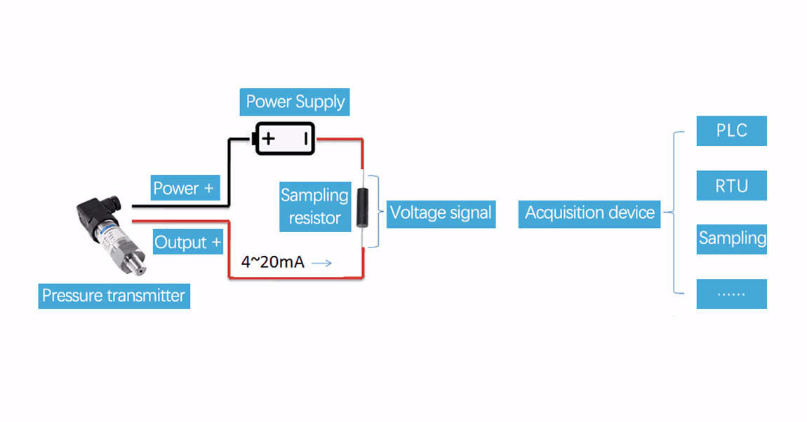
Figure 1. It is a typical usage of two-wire 4-20mA pressure transmitters for most customers showed in figure 1. After the pressure transmitter is powered on, the loop current is proportional to the pressure to generate a 4-20 mA signal by collecting the pressure. The current flow through the sampling resistor (typical 100 Ω, 250 Ω) which ...
Pressure Sensor vs Transducer vs Transmitter | TE Connectivity
4 20ma Pressure Transducer Wiring Diagram. Variety of 4 20ma pressure transducer wiring diagram. A wiring diagram is a simplified conventional pictorial representation of an electrical circuit. It shows the parts of the circuit as simplified forms, and also the power and also signal links in between the devices. A wiring diagram typically provides info about…
Wiring Diagram For Pressure Transducer
Get 4 20ma Pressure Transducer Wiring Diagram Sample. Assortment of 4 20ma pressure transducer wiring diagram. A wiring diagram is a streamlined standard photographic depiction of an electrical circuit. It shows the elements of the circuit as streamlined shapes, as well as the power and signal connections in between the gadgets.
Common Troubleshooting for 2-wire 4-20ma Pressure ...
For 4-20mA loops with 2-wire transmitters, common power supply voltages are 36VDC, 24VDC, 15VDC and 12VDC. Current loops using 3-wire transmitters can have either AC or DC power supplies. The most common AC power supply is the 24 VAC control transformer. Be sure to check your transmitter's installation manual for the proper voltage requirements.
Differential Pressure Transducer, Output 4-20mA HART | ATO.com
A) If the 4-20mA Input Device includes an Internal Sensor Power Supply and has 2 input connections: Connect Positive (+) Input connection to Positive (+) Pressure Transmitter connection; Connect Negative (-) Input connection to Negative (-) Pressure Transmitter connection; B) If the 4-20mA Input Device requires an External Sensor Power Supply and has 2 input connections:

3 Wire Pressure Transducer Wiring Diagram Sample
Wiring Diagram: 30 Pressure Transducer Wiring Diagram

Wiring Diagram For Pressure Transducer

32 4 Wire Transmitter Wiring Diagram - Wiring Diagram Database
2 Wire Pressure Transducer Wiring Diagram - Current Loop ...

Pressure Transducer Wiring Diagram

4 20ma Wiring Diagram - Fuse & Wiring Diagram

4 20Ma Pressure Transducer Wiring Diagram / Water Air Oil ...

4 20ma Circuit Diagram - Wiring Diagram Networks

4 20ma Pressure Transducer Wiring Diagram | Free Wiring ...
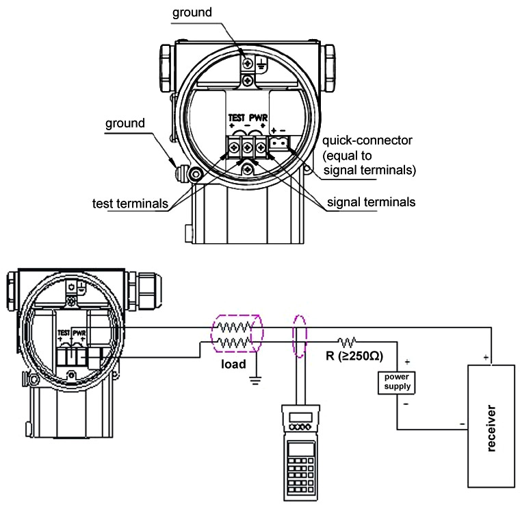
OMEGA ENGINEERING - Pressure Transducers - Installation ...
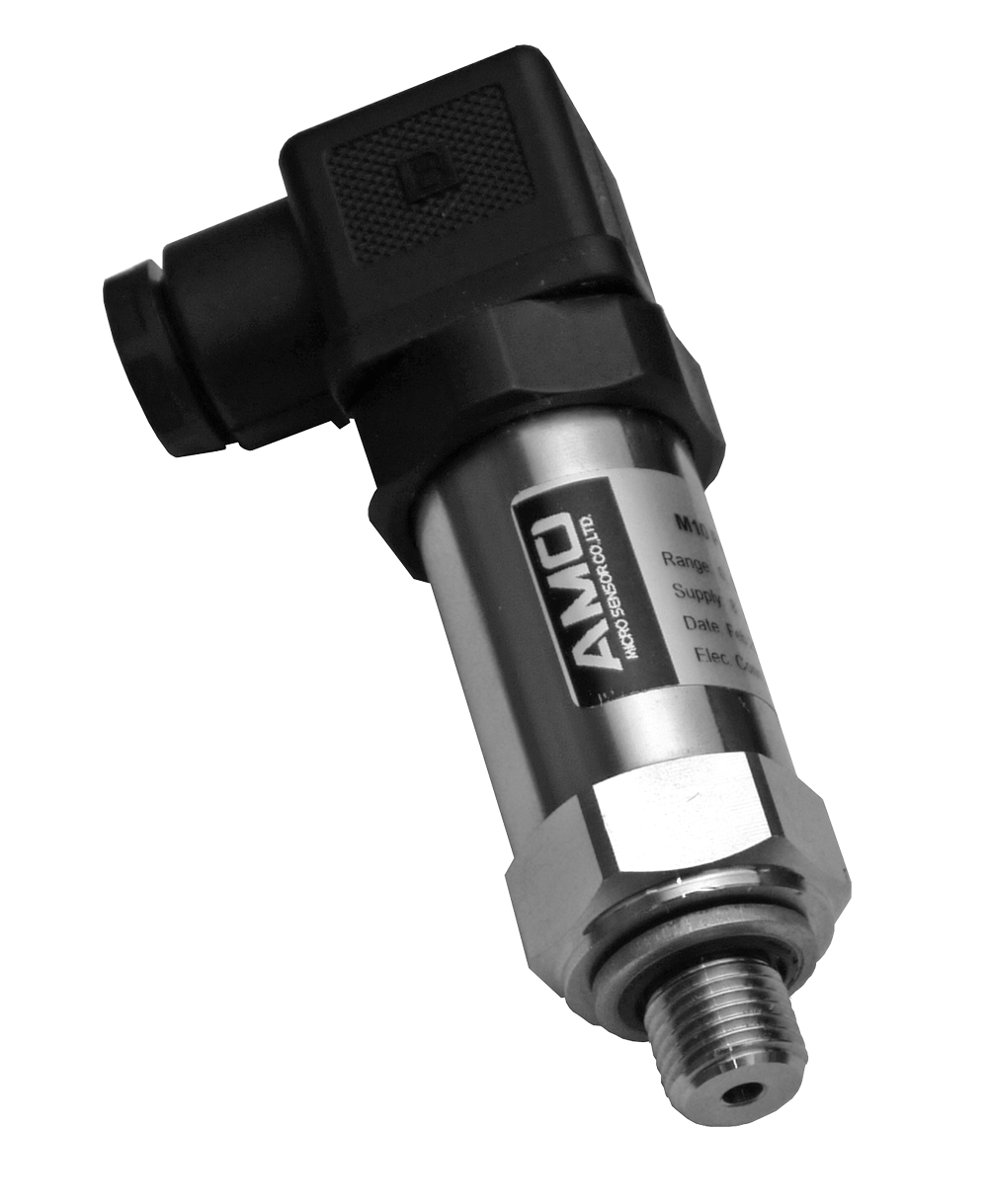
AMO M10 Budget Industrial Pressure Transducer 4-20mA ...

Wiring Diagram For Pressure Transducer

4 20ma Pressure Transducer Wiring Diagram | Free Wiring ...

4 20Ma Pressure Transducer Wiring Diagram / 2 Wire 4 20 Ma ...

Liquid Differential Pressure Sensor 4-20mA 0-0.4 bar - Buy ...

wilbo666 / 4-20mA

4 20ma Wiring Diagram - Wiring Diagram Networks

4 20ma Wiring Diagram - Fuse & Wiring Diagram

4 20ma Pressure Transducer Wiring Diagram | Free Wiring ...
4 20Ma Pressure Transducer Wiring Diagram / 2 Wire 4 20 Ma ...
0 Response to "35 4-20ma pressure transducer wiring diagram"
Post a Comment