34 draw a ray diagram of the lens system you set up in c6
The ray nature of light is used to explain how light refracts at planar and curved surfaces; Snell's law and refraction principles are used to explain a variety of real-world phenomena; refraction principles are combined with ray diagrams to explain why lenses produce images of objects.
If R is the radius of curvature of the lens and r is the distance of the point under consideration to the point of contact of the lens and glass plate, then. R 2 = (R-t) 2 + r 2. or, R 2 = R 2 - 2Rt + t 2 + r 2. or, 2t = r 2 /R = D 2 /4R. since t 2 << r 2 and D = 2r, the diameter of a ring.. Combine this result with the condition for the m th and n th dark rings. Then, the diameters of the ...
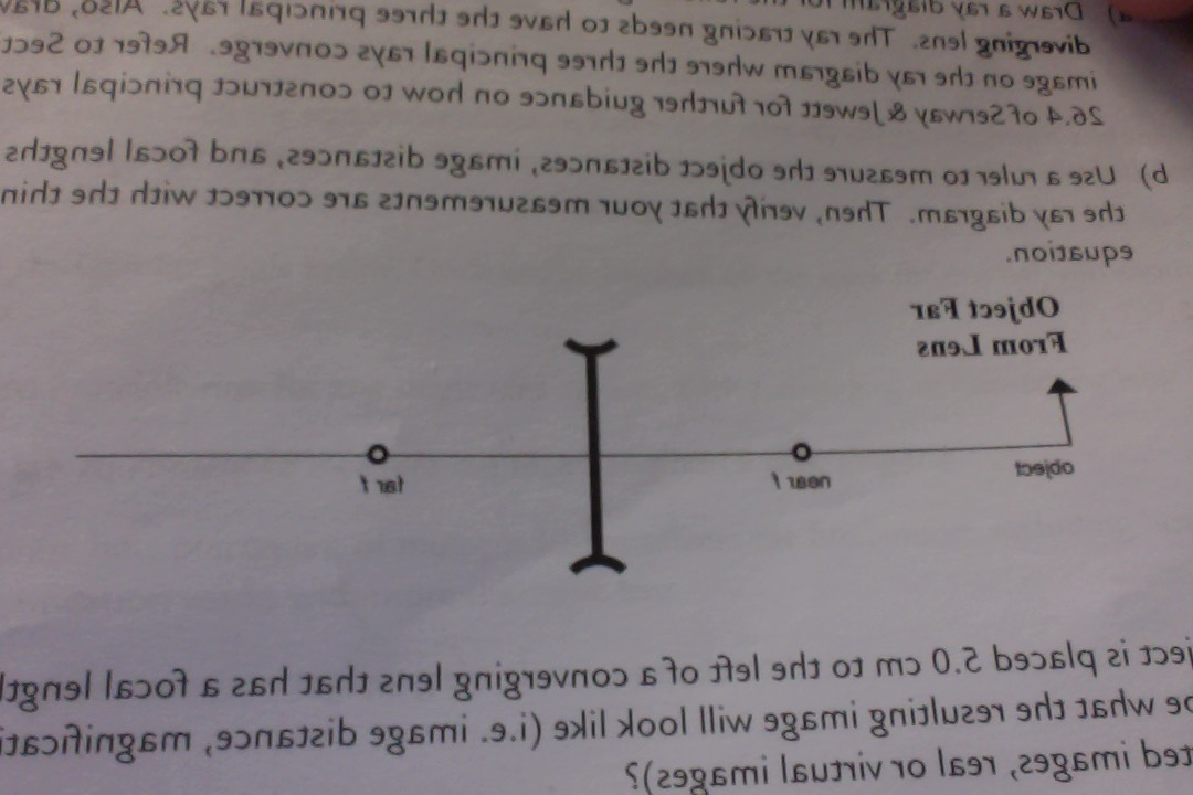
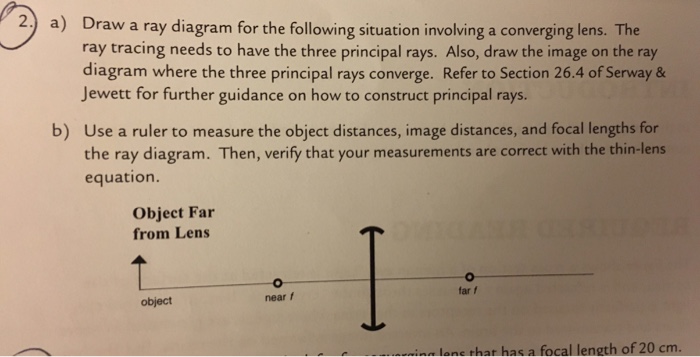
Draw a ray diagram for the following situation involving a converging lens. The ray tracing needs to have the three principal rays. Also, draw the image on the ray diagram where the three principal rays converge. ... Assume that you get a lens 6 from your TA and set up the lens system with the light source. At a certain object distance and ...

Draw a ray diagram of the lens system you set up in c6
Fig. 6.1 shows a plane mirror and a convex lens. FF P O ... In the space below, draw a diagram to represent a sound wave. On your diagram, mark and label ... In the space below, draw a labelled diagram of the apparatus set up so that electromagnetic induction may be demonstrated. [2] (c) ...
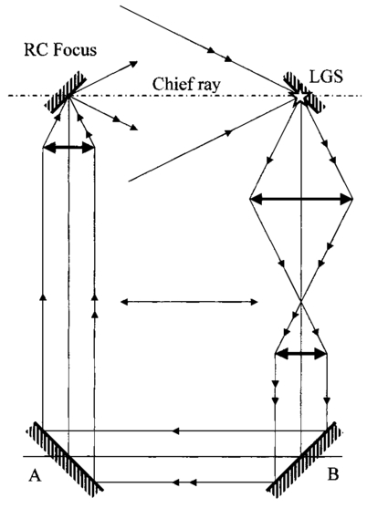
This diagram was drawn as part of a guide to new users of the tweezer system as although specific ray optics are not accurately shown, ALL optical elements are shown with their relative positions ...
Two lens system - Image distance and magnification. Home Problems and Answers Optics Two lens system - Image distance and magnification . Two converging lenses, with the focal length f 1 = 10 cm and f 2 = 15 cm are placed 40 cm apart, as shown on the figure. An object is placed 60 cm in front of the first lens as show in second figure.
Draw a ray diagram of the lens system you set up in c6.
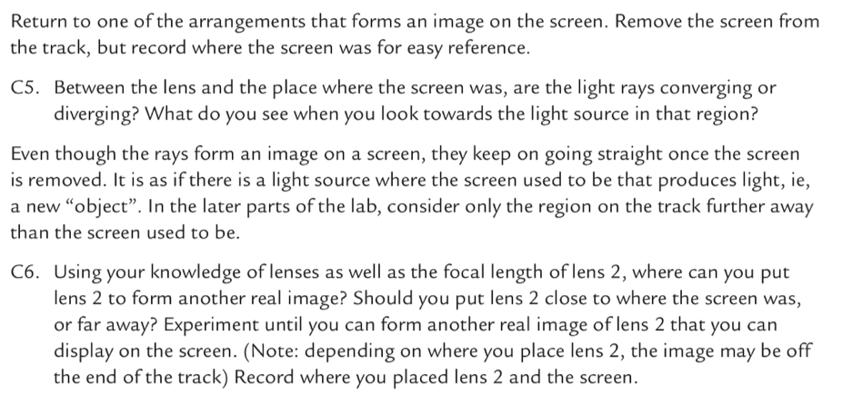
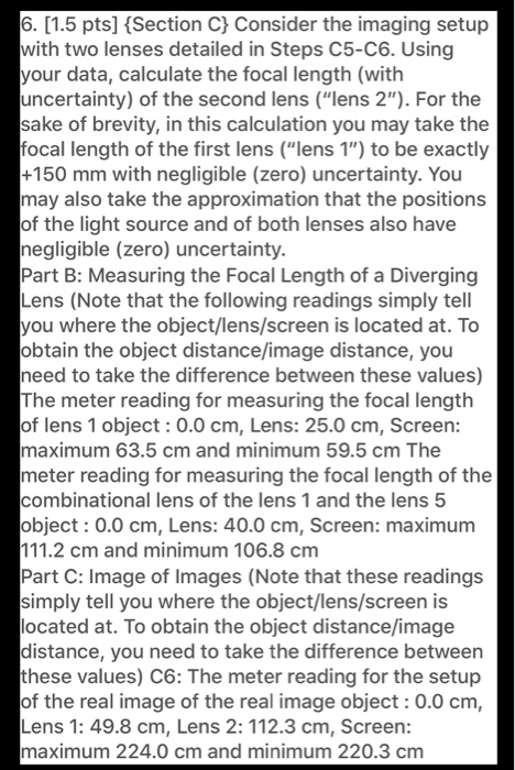
To obtain the object distance/image distance, you need to take the difference between these values) C6:The meter reading for the setup of the real image of the ...4 answers · Top answer: So discussion belongs to the chapter lens and optical instrument and which says that a line ...
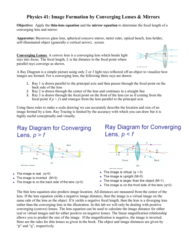
A real image is an image that can be projected onto a screen. A virtual image appears to come from behind the lens. To draw a ray diagram: Draw a ray from the object to the lens that is parallel ...
This physics video tutorial focuses on a multiple two lens system that contains a diverging lens and a converging lens. It provides the thin lens equation n...
Based on your ray diagrams on page 2 and 3 in the Lenses lab that you ... diagram of the lens system as it should look at the end of Step C6 (the setup for ...
The focal length of our lens is = _____meters B.) Draw a ray diagram of what is happening with the lens. We will assume that the rays of light coming into the lens are coming from "infinity" so that it enters the lens parallel. 2.) Playing with the object and image distances Take a moment to play with the following ray tracing applet:
a) For convenience of discussion we assume that the light passes through the lens from left to right. Ray diagrams will follow this convention. (b) The focal point of a lens is found by allowing a bundle of mutually parallel rays to enter the lens (i.e., from an object infinitely far from the lens). The lens alters the direction of these rays,
One 2-lens setup that is very useful in a laser lab is called a Beam Expander. To create a beam expander, you set two lenses in your laser beam path and separate them by the sum of their focal lengths. You have two lenses, lens 1 with f 1 = 20 cm and lens 2 with f 2 = 40 cm. You set them up separate by f 1 + f 2 = 60 nm. Laser light enters lens 1.
Nov 21, 2018 — Draw a ray diagram to show the nature, size and position of the image formed when the object is kept at a distance of 55 cm,35 cmand 15 cm from ...2 answers · 75 votes: Given focal length of the lens is f= 20cm so 2f =40cmCase1 When the object is kept at a distance ...
Geometrical Construction of Ray Diagrams. A popular method of representing a train of propagating light waves involves the application of geometrical optics to determine the size and location of images formed by a lens or multi-lens system. This tutorial explores how two representative light rays can establish the parameters of an imaging scenario.
Step-by-Step Method for Drawing Ray Diagrams. The method of drawing ray diagrams for double convex lens is described below. The description is applied to the task of drawing a ray diagram for an object located beyond the 2F point of a double convex lens. 1. Pick a point on the top of the object and draw three incident rays traveling towards the ...
the image distance for the first lens and the separation between the two lenses. Be careful of the sign. 4. Consider again Problem 3, but for the case when d < (f 1 + f 2). Draw a ray diagram clearly indi-cating the rays from the object through the first lens to an image. Draw another diagram indicat-
For aconvex lens, we draw the ray diagram as follows: Draw a ray from the top of the object straight through the middle of the lens. Its direction is not changed. Draw a ray from the top of the object parallel to the principal axis. It is refracted by the lens to pass through the focal point. F From the diagram we see that the image in this ...
Drawing ray diagrams for a converging lens - the fizzics ...
Procedure: Adjust until the system is at rest / read each force or Newton ... (i) Draw a labelled diagram of the apparatus used in the experiment.166 pages

Ray diagram for a combination of two lenses (blue disks) with ...
Draw a ray diagram of the lens system as it should look at the end of Step C6 (the set up for forming the image of areal image).Draw the ray diagram roughly to scale and label all lengths (based on the values given in the data set.) b. Describe in one sentence the final image as accurately as possible (characterize its type and its appearance ...
2. the tem and its optics
Our top 5% students will be awarded a special scholarship to Lido. Q40) Draw a ray diagram to show the formation of image of an object placed on the principal axis of a convex mirror. State the position, size and nature of the image. What happens to the image as the object is moved away from the mirror?
Draw a ray diagram of the lens system you set up in c6 ...
Defining the lens system data . ... Extending the rays in the lens drawing . ... the diagram, click on the Setup Window/Toolbar icon in the.135 pages
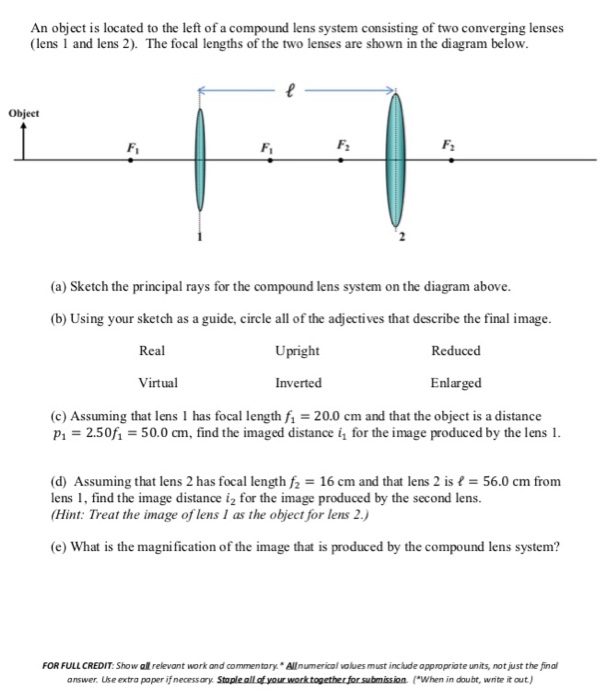
Solved an object is located to the left of a compound lens ...
Ray Diagrams Object N F Image Let's check the answer by making a quick ray diagram of the situation: Ray 1: parallel then away from near focal point. Ray 2: straight through the center of the lens. Ray 3: is intended to go through far focal point but goes parallel at lens. Image is upright, diminished and virtual.
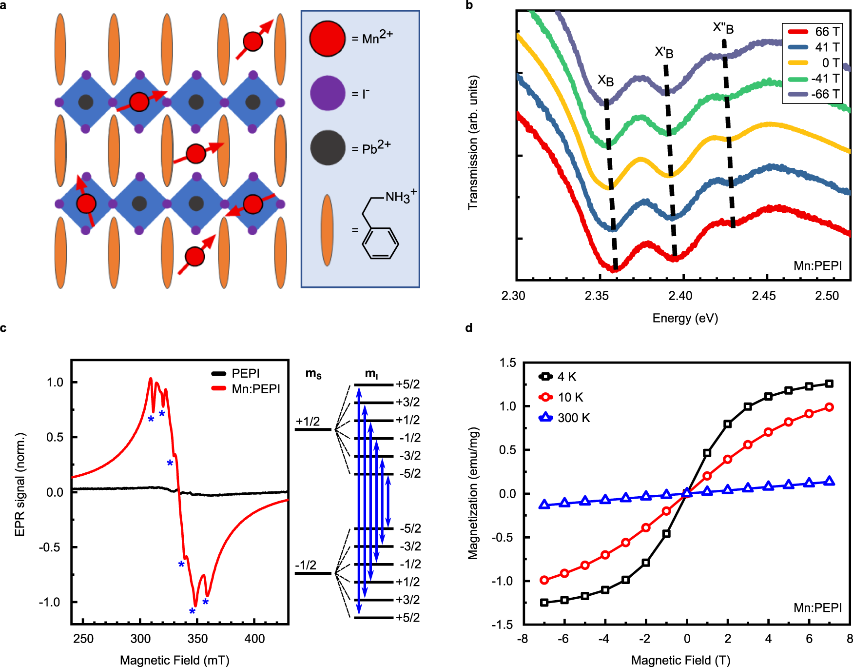
Manganese doping for enhanced magnetic brightening and ...
Draw ray diagrams and explain your reasoning. When the light hits the plastic block it bends (refracts). Since the plastic has a higher index of refraction, the light bends toward the normal (perpendicular) line. Then, when it reenters the air, it bends away from the normal. This bend ends up bending back to the original angle, but now it is
Solved a) draw a ray diagram for the following situation (an ...
Ray diagram for an object placed between 2F and F from a convex lens In a film or data projector, this image is formed on a screen. Film must be loaded into the projector upside down so the ...
Solved draw a ray diagram of the lens system as it should ...
The method is applied to the task of drawing a ray diagram for an object located beyond the center of curvature (C) of a concave mirror. Yet the same method works for drawing a ray diagram for any object location. 1. Pick a point on the top of the object and draw two incident rays traveling towards the mirror.
Physics tutorial: refraction and the ray model of light
The diagram below shows this set-up for the case of an object placed 15 cmin front of a 10-cm focal lengthconverging lens. Figure 2.3 When drawing a ray diagram, it is always important to remember that light is reflected or emitted by every point on the object.

Different lens ray diagram questions | evan's space
Concave Mirror Ray Diagram. Concave Mirror Ray Diagram lets us understand that, when an object is placed at infinity, a real image is formed at the focus. The size of the image is much smaller compared to that of the object. When an object is placed behind the center of curvature, a real image is formed between the center of curvature and focus.

Drawing ray diagrams for a converging lens - the fizzics ...
1.1 Purposes of the fluidic system of a flow cytometer ... II Setup—Instrument setup and quality control ... employs collection and collimation lenses.517 pages

(a) draw a labelled ray diagram to shwo the formation of image in a convex mirror when the object
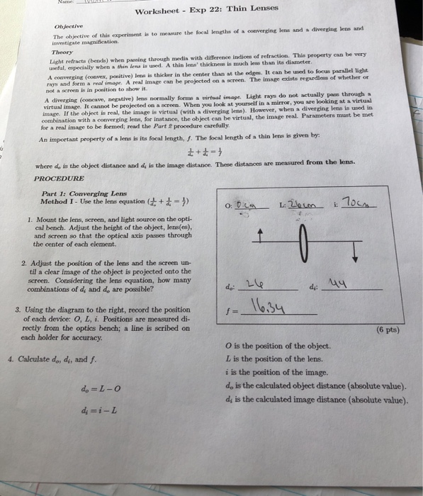
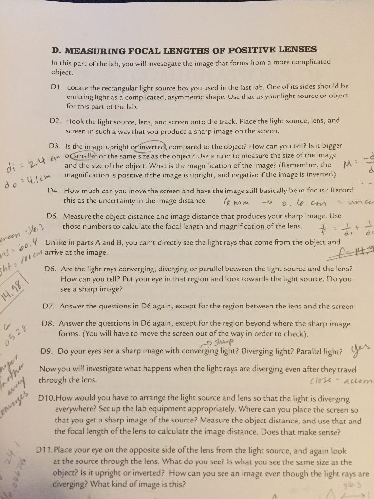
Connect the power supply to the light source. Do not turn the light on until you have everything set up on the track. Part 2 (Single +250 mm convex lens) 5. Place the 25 cm convex lens at 20 cm distance from the object, then place the viewing screen on the other side of the lens and try to form a focused image on the screen.

A) draw a ray diagram for the following si... | clutch prep
Jimmy87. 660. 13. When you look up a ray diagram for a telescope you get the following: From reading my book it seems clear that the objective lens forms and image on the focal plane. This then serves as an image for the eyepiece. Since the focal length of the eyepiece at the focal length of the objective lens you get a virtual image at infinity.
Solved 2.) a) draw a ray diagram for the following situation ...
A ray diagram shows the path of light from an object to mirror to an eye. A ray diagram for a convex mirror shows that the image will be located at a position behind the convex mirror. Furthermore, the image will be upright, reduced in size (smaller than the object), and virtual. This is the type of information that we wish to obtain from a ray diagram.
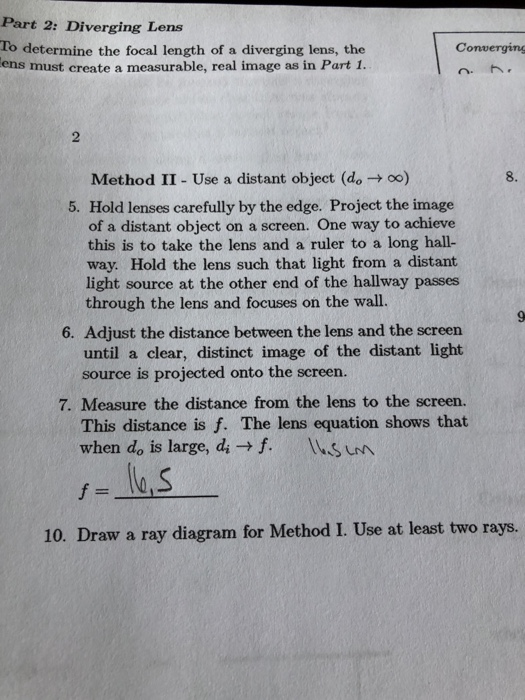
Solved 10. draw a ray diagram for method i. use at least two ...
You can draw your setup using LaTeX with several PSTricks packages: pst-optexp - for beam and fiber optics. pst-optic - for ray optics. Many components are predefined and can be connected ...

Draw a ray diagram of the lens system you set up in c6 ...
Mar 14, 2016 — Also draw the image on the ray diagram where the three principal rays converge. Although convex and concave lenses might look different the ...
Solved 10. draw a ray diagram for method i. use at least two ...
This is the second image that this lens system is going to create and so I'll just put di. Alright, so we do the math, alright 1 over negative 10 centimeters minus 1 over 15 centimeters equals 1 over di, you solve that on the left hand side. You flip it over, you're going end up getting the di is, once you do that inversion negative 6 centimeters.

Draw a ray diagram of the lens system you set up in c6 ...
Figure 27-5 A two-lens system! In this system, a convex and a concave lens are separated by 50.0 cm. (a) An object is placed 20.0 cm to the left of the convex lens, whose focal length is 10.0 cm. (b) The image formed by the convex lens is 20.0 cm to its right. This image is the object for the concave lens.
![Solved 10. (1.5 pts] {Section C} a. Draw a ray diagram of ...](https://media.cheggcdn.com/media/74c/74c29763-952b-4550-947f-37f0d6c3fb35/php5yYACe)
Solved 10. (1.5 pts] {section c} a. draw a ray diagram of ...
Draw a ray diagram of the lens system as it should look at the end of Step C6 (the setup for forming the image of a real image). Draw the ray diagram roughly to ...
Lab 9: ray diagrams
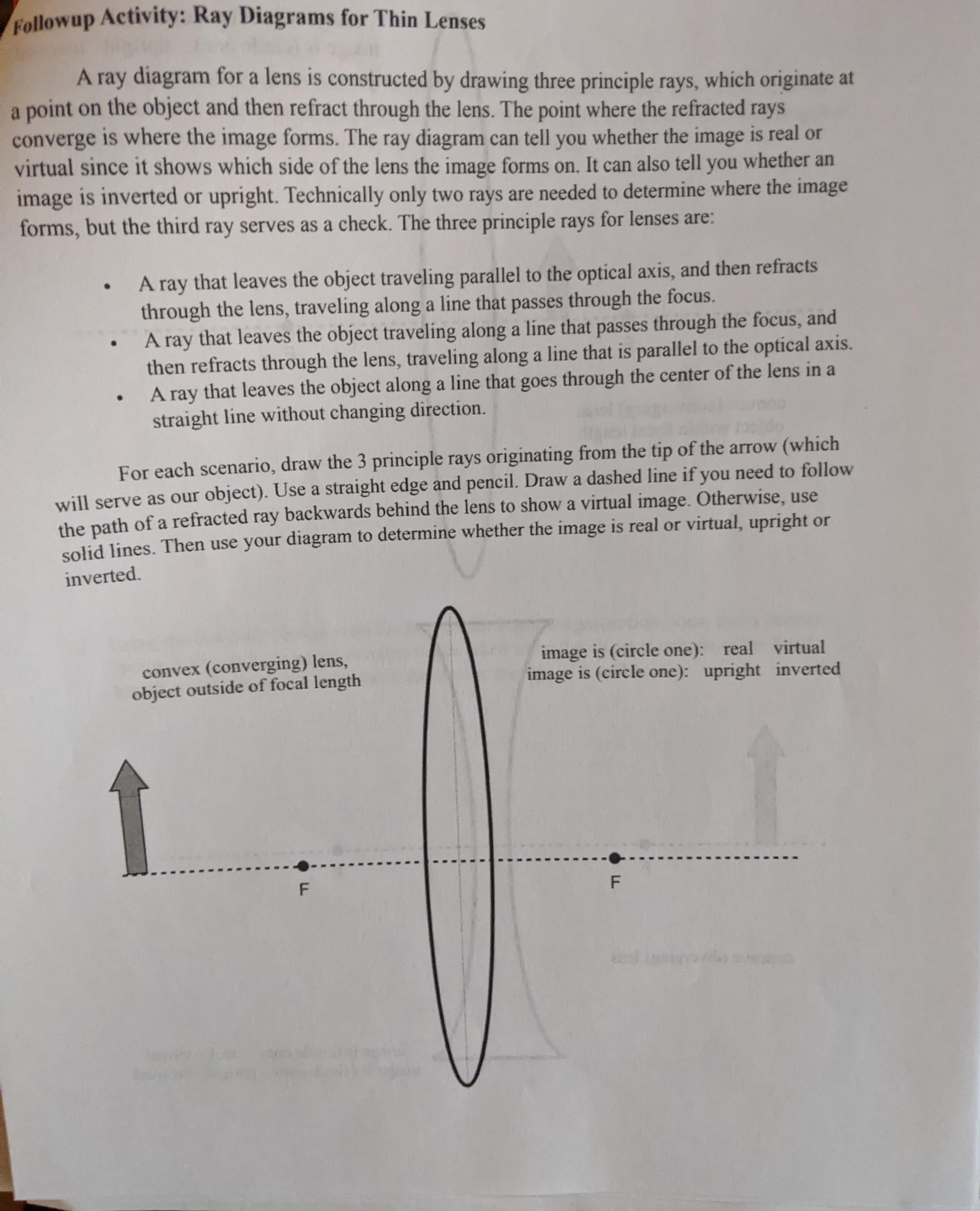
Solved followup activity: ray diagrams for thin lenses a ray ...
A) draw a ray diagram of the lens system as it | chegg.com
Physics tutorial: refraction and the ray model of light
Draw a ray diagram of the lens system you set up in c6 ...
Drawing ray diagrams notes
Solved lens 1 @ 56 cm lens 2 @ 74.8cm screen @ 77.5 cm size ...
Please help! i am not good a drawing ray diagrams, | chegg.com

Ray diagrams & lenses: physics lab video
Please help! i am not good a drawing ray diagrams, | chegg.com
A draw a ray diagram of the lens system as it should look at the end of step c6 the setup for forming the image of a real image draw the ray diagram roughly to scale and label all lengths ba 52282

We are given a convex lens of focal length 20cm .draw a ray ...
Draw a ray diagram of the lens system you set up in c6 ...
Draw a ray diagram of the lens system you set up in c6 ...
0 Response to "34 draw a ray diagram of the lens system you set up in c6"
Post a Comment