45 the diagram shows the cross section of a wire
PDF Magnetism - IG Exams (a) The diagram shows a cross-section through a wire placed between two magnetic poles. The wire carries electric current into the page at X. The shape of the magnetic field is shown. (1) (i) Add arrows to two of the magnetic field lines to show the direction of the magnetic field. Answered: The figure shows a cross section of… | bartleby The figure shows a cross section of three parallel wires each carrying a current of 24 A. The currents in wires B and C are out of the paper, while that in wire A is into the paper. If the distance R = 25.0 mm, what is the magnitude of the force on a 4.0-m length of wire A?
Cable Cross-Sections | Inside of a Cable | ShowMeCables.com The final section is the center conductor at the core of the cable. This is a conductive metal line (typically made from either copper or copper-clad steel) designed to transmit the signal going through the cable. A core can be solid or stranded. As the most important part of the cable, it is heavily protected by the first three layers.

The diagram shows the cross section of a wire
[University Physics] Electromagnetism : HomeworkHelp You want to use the formula for current. I = nqAv For wire 1, consider a small ring of radius r with thickness dr. Then the area of this ring is (2πr)dr. On your diagram, this would be represented by a circle on the face of the wire. Then the current, dI, going through this ring would be given by dI = nq (2πrdr) (v* 0 * (1 - r/R )) › suzukiSUZUKI - Motorcycles Manual Pdf, Wiring Diagram & Fault Codes Jul 05, 2022 · Suzuki Motorcycle Manuals PDF & Wiring Diagrams download free - Bandit, Burgman, DL, GR, FA, FX, Haybusa, Intruder, Marauder, PE, Raider, SVT500, V-Storm, Volusia VL ... PDF theonlinephysicstutor (a) The diagram shows a cross-section through a wire placed between two magnetic poles. The wire carries electric current into the page at X. The shape of the magnetic field is shown. (i) Add arrows to two of the magnetic field lines to show the direction of the magnetic field.
The diagram shows the cross section of a wire. › exams › potentiometerPotentiometer: Definition, Types and Applications - Embibe Jun 24, 2022 · The potentiometer wire generally has a high resistivity \(\left(\rho \right)\) and uniform cross-sectional area. Let it be \(A\). Thus, resistance would be uniform throughout the wire. This potentiometer terminal is connected to the cell of high EMF \(V\) (neglecting its internal resistance) called the driver cell or the voltage source. Pre-Assessment Earth Science Regents Course Quiz - Quizizz Arrows in the diagram above show three methods of energy transfer labeled A, B, and C. ... The cross section represents the landscape features and rock units of the Grand Canyon region in the southwestern United States. The names and ages of some rock formations are shown. ... The photograph shows wire netting installed over a steep rock ... MFJ-949E Versa Tuner II Instruction Manual SWR can be read on the illuminated cross-needle meter. The MFJ-949E uses a "T" matching network and covers all bands between 160 and 10 meters. This network will tune dipoles, inverted-vees, verticals, mobile whips, beams, random wires, and many other antennas. The MFJ-949E has rear panel connectors for coaxial, single wire or two wire feedlines. Electric Wire - Calculating Cross-Section Areas A = cross-section area (mm 2, in 2) D = diameter (mm, in) Cross-Section Area Calculator - Single Wire. Diameter (mm) Electric Wire Resistance ; Cross-Section Area of Bunched Wire. The cross-section area of bunched wires can be calculated as. A = n d 2 π / 4 = 0.7854 n d 2. where . n = number of wires. d = single wire diameter (mm, in) Cross ...
PDF 1. The diagram below represents magnetic lines of 4. In which diagram ... Each diagram below represents a cross section of a long, straight, current-carrying wire with the electron flow into the page. Which diagram ... The diagram below shows a coil of wire (solenoid) connected to a battery. The north pole of a compass placed at point P would be directed toward point (1) A (3) C (2) B (4) D Potentiometer: Definition, Types and Applications - Embibe 24.6.2022 · It works on the principle that the potential drop across a segment of a wire of uniform cross-section carrying a constant current is directly proportional to its length. To calculate unknown potential: Let \(K = V/L\) be the potential gradient of the given potentiometer, where \(V\) is the potential difference between two points and is the distance between two points. The diagram shows a circuit designed by a student to The free end of the ruler is raised and the balance is turned on and then set to zero, as shown in Figure 1. Figure 1 The ruler is then supported by the prism with the apex of the prism at the 30.0 cm mark as shown in Figure 2. The height of the pivot is adjusted so that the ruler is horizontal. Figure 2 (a) Deduce the mass of the ruler.. Section 3 - THE HAZARD ANALYSIS AND CRITICAL CONTROL … The objective of Section 3 is to review the tasks in the application of the HACCP system and to provide trainees with the knowledge and background necessary to establish HACCP plans and/or verify the acceptability of existing HACCP plans and systems. Section 3 reviews the 12 tasks in the application of HACCP, including the seven HACCP principles.
Camper Van Electrical Design with Detailed Wiring Diagram 22.4.2022 · The diagram above outlines in the most simplistic terms, my camper van electrical design. Using the formula explained here, I calculated I’d need about 80 amp hours (ah) per day including contingency. Assuming the batteries are 50% efficient, I’d need to fit 160ah batteries. A steel wire of length 2 m is hanging from a rigid horizontal support ... D 1000kg The diagram shows a horizontal steel girder AB of length 1m, area of crossection 10 cm2, from the ends of which a load of 1000 kg is suspended by two strings of length 1m each. The strain produced in the girder is (g = 10 ms 2, Y = 2 x 10¹¹N/m2) steel (1) 5*102 (2) x10-5 sa -10% (43 Fax 10-4 vertical nosi Solution Verified by Toppr PDF Unit: KPH0/4PH0 Paper: 2P - Edexcel (a) The diagram shows a cross-section through a wire placed between two magnetic poles. The wire carries electric current into the page at X. The shape of the magnetic field is shown. (i) Add arrows to two of the magnetic field lines to show the direction of the magnetic field. (1) Answered: Figure 2 below show cross section of… | bartleby Transcribed Image Text: 2. Figure 2 below show cross section of two long straight wire separated by distance 0.5 m. Wire 2 carries current 2.0 A directed into the page. Determine the magnitude and direction (into or out of the page) of the current in wire 1 if the resultant of the magnetic field due to the two wire is zero at point Q located 0 ...

Digging a Shallow Well - Do It Yourself - MOTHER EARTH NEWS
› radar-cross-sectionRadar Cross Section - an overview | ScienceDirect Topics The figure shows the (x, y, z) coordinates (z = 0 in this case) of all the points interconnecting the wire segments. The NEC code is used again to solve for the scattered field observed at angles θ and φ. The program will then calculate the bistatic scattering from Eq. (4.252).

The Diagram Shows The Cross Section Of A Wire Carrying Conventional ...
Solved The diagram shows the cross section of a wire | Chegg.com The diagram shows the cross section of a wire carrying conventional positive current towards us out of the plane of the paper. (You may ignore the earth's magnetic field) a) By means of an arrow on the diagram, show the direction in which a compass would point if placed at location A and describe the rule you use to remember this effect.

The Manchester (e,2e) Experimental Hardware page prepared by Andrew ...
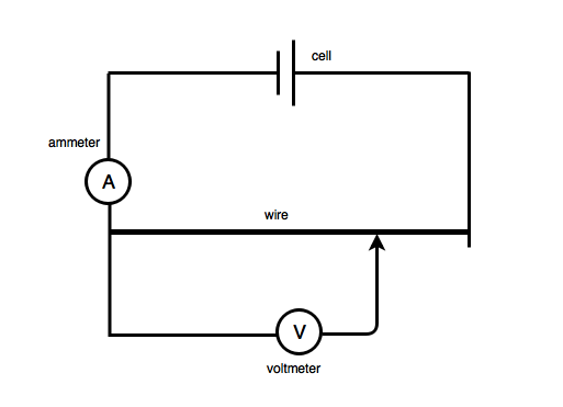
PDF The units of physical quantities can be expressed in terms of the ... The diagram shows two wires, P and Q, of equal length, joined in series with a cell. A voltmeter is connected between the end of Q and a point X on the wires. The p.d. across the cell is V. Wire Q has twice the area of cross-section and twice the resistivity of wire P. The variation of the

Patent US20030178727 - Wiring structure and method of forming the same ...
ieltsliz.com › ielts-diagram-model-answer-score-9IELTS Diagram: Model Answer Band Score 9 It is possible to have a diagram in your IELTS writing task 1 academic paper. A diagram is also known as a process. The diagram shown below is from IELTS Cambridge Book 8, Test 3. The diagram below shows the stages and equipment used in the cement-making process, and how cement is used to produce concrete for building purposes.

The Diagram Shows The Cross Section Of A Wire - Ekerekizul
Wireless Mobile Charger Circuit Diagram - Engineering Projects 15.4.2017 · The project Wireless Mobile Charger Circuit Diagram posted here can deliver 271mA at 5.2V so ... High swg wire means larger cross section area. Thus, used for high current. So ... not able to measure the output frequency so i measure the voltage but at 1st and 3rd terminal from vcc of IRF540 mosfet shows approximately 12v but ...
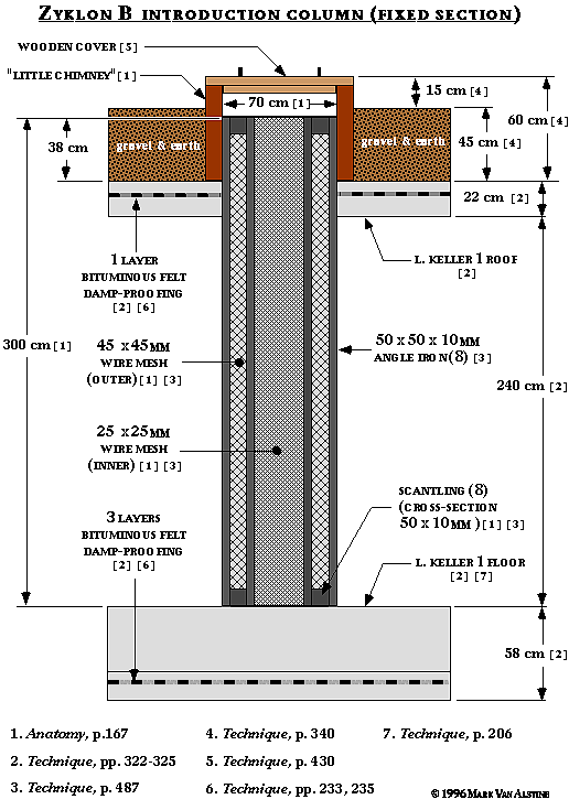
Zyklon Introduction Columns
ES-Jun 2017 Q31-40 | Earth Sciences Quiz - Quizizz Q. Base your answers to questions 9 and 10 on the diagrams below and on your knowledge of Earth science. The diagrams represent four columns, labeled A, B, C, and D, that are partially filled with equal volumes of dry, sorted sediments. A fine wire mesh screen covers the bottom of each column to prevent the sediment from falling out.

3D model of the assembly with its integrated cooler. A cross-section of ...
mowgli-adventures.com › camper-van-electrical-designCamper Van Electrical Design with Detailed Wiring Diagram Apr 22, 2022 · In the diagram above, I’ve indicated the output to the smart relay and the isolator from the leisure batteries, as explained a little earlier. The remainder of the diagram shows the set up of the output components. Cabling is run between the leisure batteries, fuses, switches and components as detailed above.
Electrical system
Answered: The figure shows a cross section of… | bartleby The figure shows a cross section of three parallel wires each carrying a current of 24 A. The currents in wires B and C are out of the paper, while that in wire A is into the paper. If the distance R = 5.0 mm, what is the magnitude of the force on a 4.0-m length of wire C?

Patent US7126452 - Wiring structure, and fabrication method of the same ...
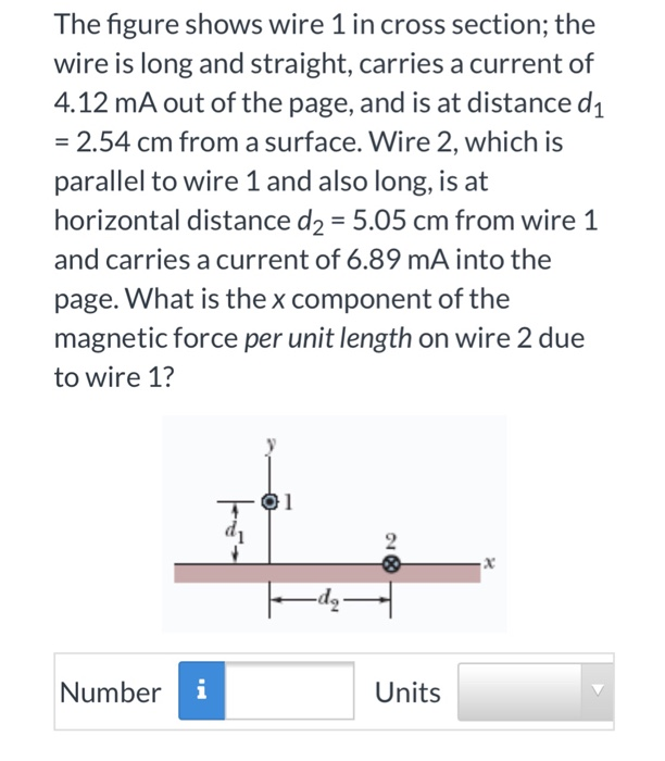
Answered: The figure shows wire 1 in cross… | bartleby The figure shows wire 1 in cross section; the wire is long and straight, carries a current of 4.06 mA out of the page, and is at distance di = 2.40 cm from a surface. Wire 2, which is parallel to wire 1 and also long, is at horizontal distance d2 = 5.32 cm from wire 1 and carries a current of 6.90 mA into the page.

The Diagram Shows The Cross Section Of A Wire Carrying Conventional ...
R x 2R 31. The diagram above shows the cross section... - Physics R x 2R 31. The diagram above shows the cross section of a long cable that has an inner wire of radius R surrounded by a conducting sheath of outer radius 2R. The wire and the sheath carry currents in opposite directions but with the same uniform current density J. What is the magnitude of the magnetic field at the surface of the outer conductor?

Example design of destructive wire burning showing burning element and ...
Two Wire Comparison - Physics Forums #1 Winzer 598 0 Homework Statement The diagram shows two wires; wire 1 and wire 2. The charge carriers in wire 1 (of circular cross section and radius R) have a drift speed down the wire that is not constant across the wire.

The Diagram Shows The Cross Section Of A Wire Carrying Conventional ...
› schemi › ACC_matchingMFJ-949E Versa Tuner II Instruction Manual - RadioManual SWR can be read on the illuminated cross-needle meter. The MFJ-949E uses a "T" matching network and covers all bands between 160 and 10 meters. This network will tune dipoles, inverted-vees, verticals, mobile whips, beams, random wires, and many other antennas. The MFJ-949E has rear panel connectors for coaxial, single wire or two wire feedlines.

The Diagram Shows The Cross Section Of A Wire Carrying Conventional ...
PDF International GCSE Physics - Edexcel (b) The diagram shows a cross-section through a wire placed between two magnetic poles. The wire carries electric current into the page at X. The shape of the magnetic field is shown. (i) Add arrows to any twolines to show the direction of the magnetic field. (1) (ii) Draw an arrow on the diagram to show the direction of the force on the wire.
The Diagram Shows The Cross Section Of A Wire - Free Wiring Diagram
Solved The diagram shows the cross section of a wire | Chegg.com The diagram shows the cross section of a wire carrying conventional positive current toward us out of the plane of the paper. (You may ignore the earth's magnetic field) (a) By means of an arrow on the diagram, show the direction in which a compass would point if placed at location A and describe the rule you use to remember this effect
The Diagram Shows The Cross Section Of A Wire - Hanenhuusholli
bestengineeringprojects.com › wireless-mobileWireless Mobile Charger Circuit Diagram - Engineering Projects Apr 15, 2017 · Working Principle of Wireless Mobile Charger Circuit Diagram. Wireless Mobile Charger uses the inductive coupling principle. In this principle, two LC tuned circuits communicate at the same tuned frequency i.e. tuned frequency of the transmitter must be equal to the tuned frequency of the receiver.
Solved: The Figure Shows Wire 1 In Cross Section; The Wire... | Chegg.com
The diagram shows, in corss - section, the arrangement of aluminium and ... Question The diagram shows, in corss-section, the arrangement of aluminium and steel wires in an electric power cable Which metal wire is the better conductor and which metal wire has the greater mechanical strength? A better conductor - aluminium; greater mechanical strength - aluminium B
0 Response to "45 the diagram shows the cross section of a wire"
Post a Comment