44 universal fuel gauge wiring diagram
PDF Let Moeller Show You How! Elec ic F el Se de - Moeller Marine 1. Use measured tank depth dimension and locate float arm length (see Diagram 1.) 2. Slide float and push-on fasteners toward case until outer end of float is 5/16" (8mm) less than float arm dimension. 3. IMPORTANT: Keep 1/16" (1.75mm) space between float and inner fastener. 4. Cut float arm at float arm dimension. PROPER SENDING UNIT TANK INSTALLATION: 5. PDF Adjustable Fuel Gauge Tube-Type Fuel Sender - VDO Instruments and ready for use, and the gauge can be Wiring the Fuel Gauge: mounted. 1. Run wires from the adjustable fuel gauge location to: a) +12 volt power terminal (This positive power source MUST BE SWITCHED, and should be protected with a fuse) b) the light switch (also after the fuse in the fuse box) c) a good ground location d) the tube-type fuel sender. 2. Wire the adjustable fuel gauge and tube-
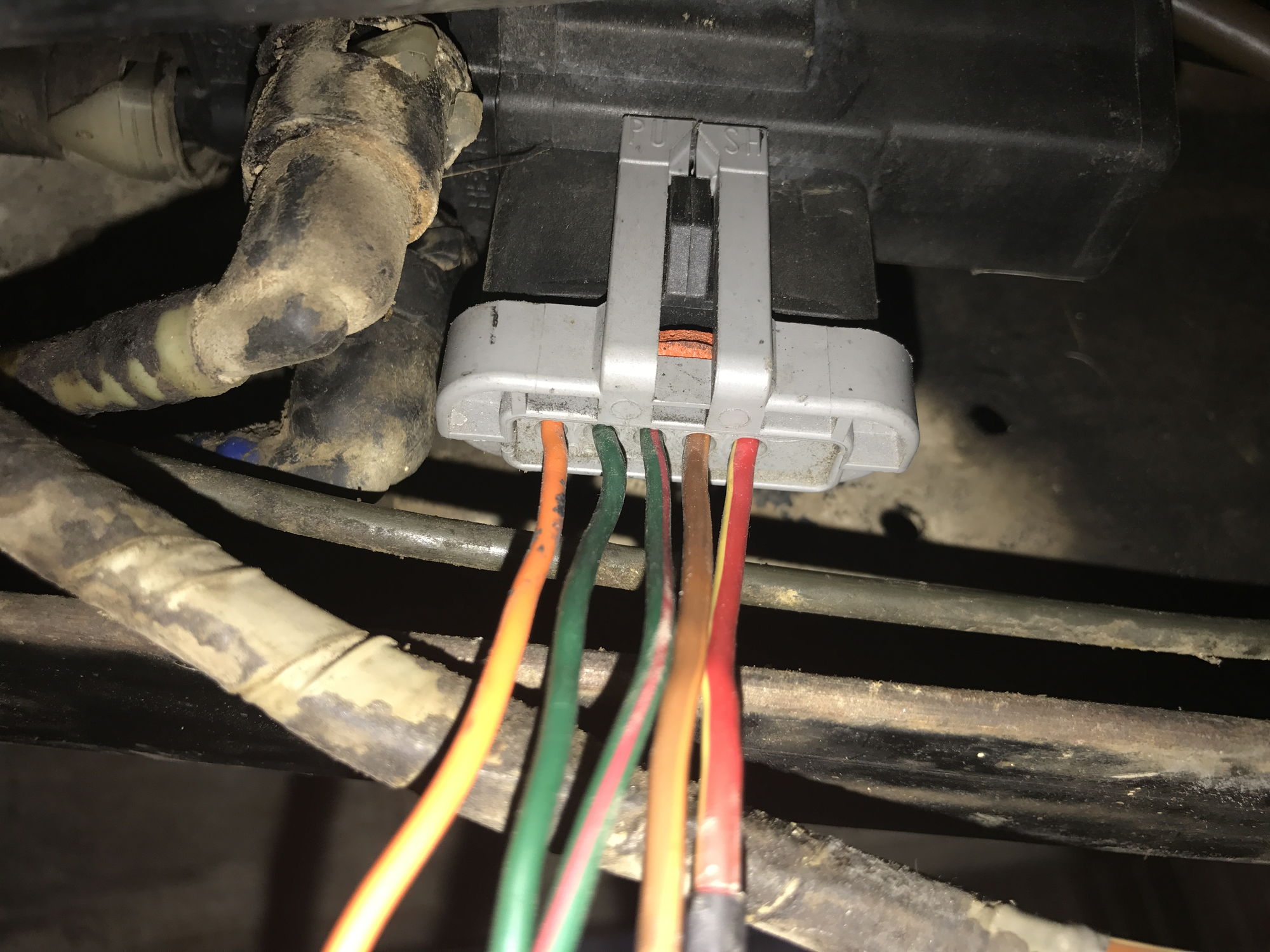
GMC Wiring Diagrams - FreeAutoMechanic Wiring Diagrams › GMC. If you run into an electrical problem with your GMC, you may want to take a moment and check a few things out for yourself. Before you dive in with a multi-meter, you will want to obtain a free wiring diagram for your specific model. You may need to locate a specific color wire and its exact location.
Universal fuel gauge wiring diagram
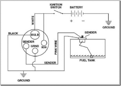
How To Check Ohms On A Fuel Gauge? (7 Steps) Check the ohms on a fuel gauge. Follow the car's manual on how to remove the fuel sending unit from your car's fuel tank. From there, what you need to do is to unplug the sender and then use a multimeter in ohms. Use the multimeter to check the ohms when the tank is empty and do so again when the tank is full. Table Of Contents. › products › ignitionMSD 7730 MSD Power Grid System - Controller Only - Red The Power Grid Ignition System is the next evolution of our Programmable 7-Series Ignition Controls. The Grid incorporates an efficient 32 bit microcontroller and an all new software program, called MSD View, and is USB compatible. The Windows based software is designed with tabs to help racers easily select different programming windows and parameters. Also, the data acquisition files of the ... The Sending Unit - How Fuel Gauges Work | HowStuffWorks The Sending Unit The sending unit is located in the fuel tank of the car. It consists of a float, usually made of foam, connected to a thin, metal rod. The end of the rod is mounted to a variable resistor. A resistor is an electrical device that resists the flow of electricity. The more resistance there is, the less current will flow.
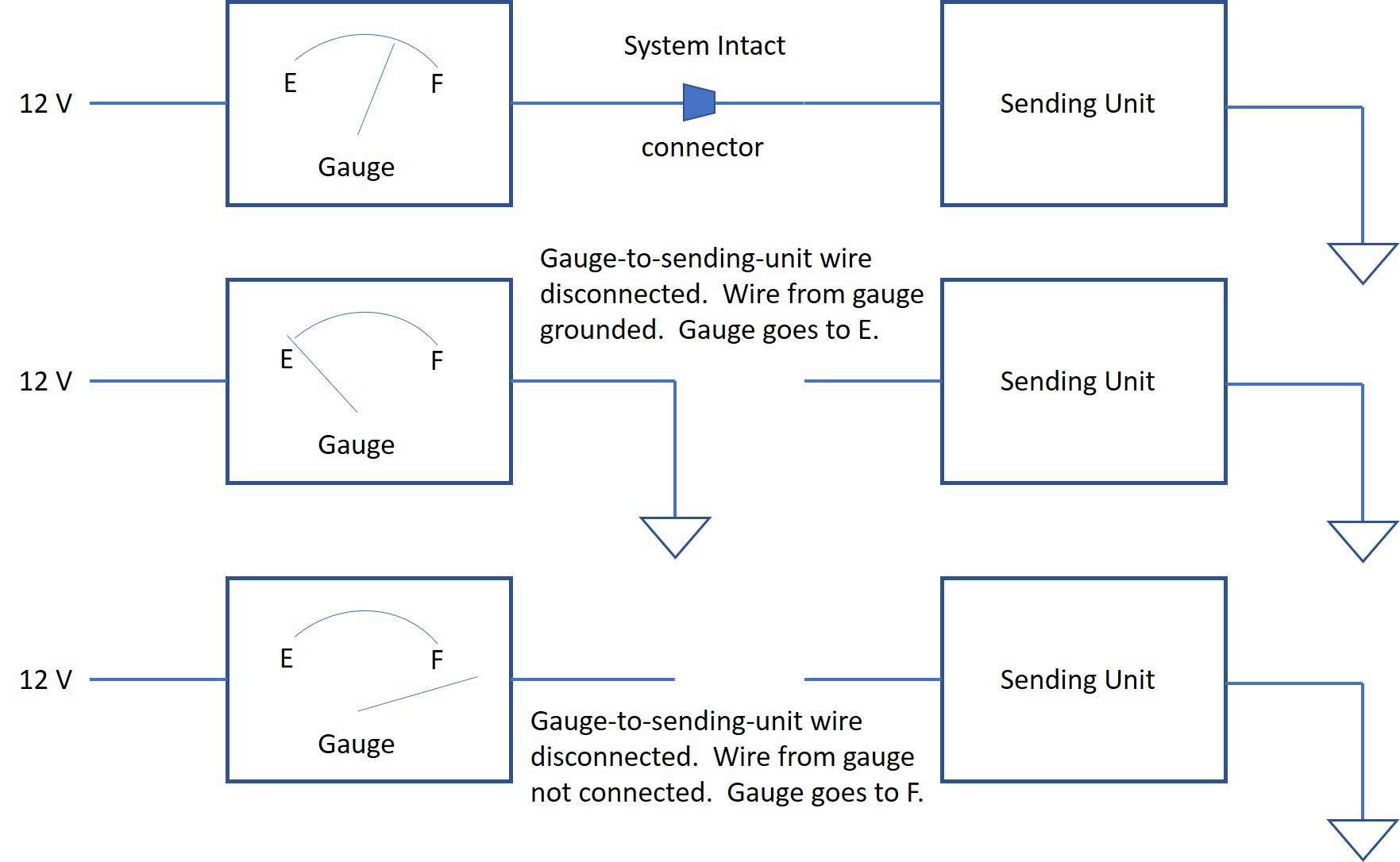
Universal fuel gauge wiring diagram. Technical Info - Seachoice Below is a list of product information for specific Seachoice items. This list is in numeric order by item number and is accompanied by a brief item description. If you do not see what you are looking for or have other technical questions please ask by visiting our "Contact Us" page. Not liable for any improper installations. fuel gauge wiring - Hot Rod Forum As the fuel level rises, more and more current from the gage goes to ground and when full, needle should read "Full or F". If the needle pegs immediately after turning the ignition on, then your sending unit is probably shorted out. Disconnect the wire from the sending unit and run twelve volts to the unit thru a volt meter. › support › fuel_injectionHolley Sniper EFI The Sniper has pre-programmed base calibrations that are a good starting point for most street drivable camshafts. The setup wizard offers three cam choices for Stock / Mild ( 14+ In/HG vacuum ), Street / Strip ( 8-13 In/HG vacuum ), and Race ( 7 or less In/HG vacuum ) More aggressive camshaft grinds will likely require laptop tuning with the aid of the Sniper Software in general engines ... tameson.com › pressure-gauge-diaphragmDiaphragm pressure gauge | Tameson.com A diaphragm pressure gauge, also known as a membrane pressure gauge, is a device that utilizes the deflection of a flexible thin membrane called the ‘diaphragm’ to measure the pressure of the fluid in a system. The membrane isolates the inner-working components of the pressure gauge from the media, preventing any contamination.
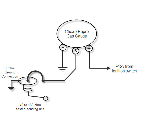
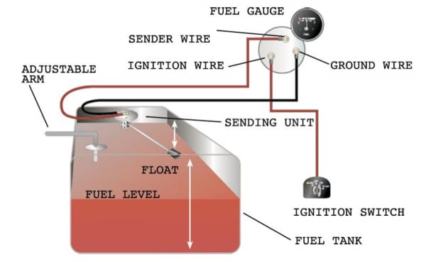
PDF INSTALLATION INSTRUCTIONS SHORT SWEEP ELECTRIC FUEL LEVEL GAUGE Wiring Wiring: Sending Unit Wiring: Gauge Mounting: Gauge to Sender Compatibility: Looking at the rear of the gauge, you will have 3 terminals labeled S, I, & GND. You may use 18g or 20g stranded wire for all fuel level gauge wiring. S = This connects to the sending unit in the fuel tank. **(See Sending Unit Wiring Section) I = Supply 12v, key on power to this terminal. It is recommended to use a 3 Amp automotive fuse when supplying power to this PDF FUEL LEVEL GAUGE INSTALLATION INSTRUCTIONS - CARiD.com Gauge to Sender Connection 5. read the fuel level tank sender instructions and install the sender. 6.RefertoFigure 3. Route a length of 18-gauge insulated copper wire from the gauge to the sender. connect the wire to the sender. onnect the other end of the wire to the connection post on the back of the gauge marked "S". 7.Make sure the fuel level sender is grounded to Universal Float Free Motorcycle Fuel Gauge FuelGaugePro The fuel gauge Sensor is connected to the fuel hose under the fuel tank. The fuel causes hydrostatic pressure measured by the Sensor. The data from this pressure sensor are evaluated by a microcomputer, which compares it to the data in its memory (the memory is set up during calibration) and then shows the current amount of fuel on the display. fuel gage wiring | Classic Parts Talk It is designed to drop 12 volts to 6 volts by inserting 1.5 ohms into the circuit. In your case, the resistance in the gas gauge is a LOT more than 1.5 ohms, so the actual voltage supplied to the gauge would be MUCH more than 6 volts. You could connect two of the Echlin parts together in series and use the center point to tap off 6 volts.
PDF Fuel Level Sender Installation Instructions - vdo-gauges.com flange and rubber gasket with those in fuel sender flange . Use 1" screw to connect top flange, gasket, and mounting flange. Leaving mounting flange as loose as possible. 2. Slip the fuel sender assembly into the 2.322" (59mm) hole in the tank, turning assembly until it goes into the tank. 3. Make certain float arm has a clear field of motion marinehowto.com › universal-diesel-engine-wiringUniversal Diesel Engine - Wiring Harness Upgrade - Marine How To Here’s a very crude diagram that shows the alternator charging circuit most often found on these early Universal diesel engines. Universal/Westerbeke Corporation later changed this incredibly dangerous set up, removed the ammeter and jumped the alternator directly to the starter lug. Fuel Level Gauge 52mm Fuel Level Gauge; Needle; Digital; Water Level Gauge. 52mm Water Level Gauge; Needle; ... autometer fuel level gauge wiring diagram. Read More. fuel level gauge kit. Read More. universal fuel level gauge kit. Read More. aftermarket "fuel level gauge" erratic fluctuating. Read More. what should my fuel level gauge be on for my silverado ... How to Test and Replace your Fuel Gauge and Sending Unit Fuel Gauge Check the wiring diagram that comes with the kit and mark the back of the new fuel gauge with symbols for each post: "S" for the sender, "G" or "—" for the ground, and "I" for the ignition. Install the new gauge, reconnect the wiring and turn on the power. The fuel gauge should now show the correct fuel level in the tank.
The Neverending Gas Gauge Dilemma - The CJ2A Page Forums
› pages › manualsEnglish Manuals - FuelTech USA Begin typing any product name to find downloadable manuals. ECUs FT600 / FT550 / FT550LITE / FT450 ManualVersion: 2.2 | Size: 20 MB FT500/FT500LITE ManualVersion: 4.2 | Size: 28 MB FT350/FT400 ManualVersion: 1.7 | Size: 7.5 MB FT250/FT300 ManualVersion: 1.7 | Size: 11.1 MB Injector Drivers & Fuel Injectors Peak and
Moeller Fuel Gauge Wiring Diagram
› suzukiSUZUKI - Motorcycles Manual Pdf, Wiring Diagram & Fault Codes Jul 05, 2022 · Hi, does anyone have a wiring diagram for lexmoto assault efi 2019, the ignition switch they sell on cmpo doesn't fit to wiring loom on bike:))). They is a 6 pin plug with red, black and brown on bike and an 6 pin plug with red, black, green, black/white on ignition switch all of them in completely different positions. Guess what, bike doesn't ...
Early Mini Fuel Gauge - adjusting it | British Car Forum
Gauges & Fuel Tank Senders - Auto Electrical Spares CLASSIC CAR universal 2" fuel gauge and sender unit 12v £29.16 £34.99 (inc. VAT) CLASSIC CAR universal 2" fuel gauge and sender unit 24v
Wiring Diagram: 35 Ford Fuel Tank Selector Valve Wiring Diagram
How Do You Wire a Fuel Gauge? - Reference.com Wire a fuel gauge by first disconnecting the old dysfunctional unit to replace it with a new one. Obtain 12-volt power from the fuse box using a standard wire, and connect it to the positive terminal of the fuel gauge. Next, connect a wire from the float on the fuel tank to the negative terminal of the fuel gauge.

Fuel Gauge Wiring - Help Verify | IH8MUD Forum
PDF UNIVERSAL FUEL PUMP RELAY INSTALLATION INSTRUCTIONS - Painless Wiring 3. attach the 12 gauge (larger) yellow/white wire from the relay to the fuel pump. 4. attach the 18 gauge (smaller) yellow/white wire to a switched 12 volt source or fuel pump switch, using the red ring terminal if necessary. 5. attach the red 12 gauge wire to the circuit breaker after cutting to length, using a yellow ring terminal. 6.

How To Wire A Fuel Gauge | Boat wiring, Car fuel, Gauges
wiring to fuel gauge | Boating Forum - iboats Boating Forums 1) The wire from the "A" (accessory) terminal on the ignition switch does not have 12 volts on it with the key in the RUN position. 2) The "A" terminal feeds the gauges so that line may be loose or disconnected at the first gauge in the string. 3) Ground is disconnected from the string of gauges.

Fuel gauge wiring | Page 3 | The Late Bay
bazzaz.net › fuel-map-databaseFuel Map Database – Bazzaz Join the community to start viewing, uploading, and downloading fuel maps for your Bazzaz Z-Fi engine management systems The best tune for your motorcycle is a custom tune. Drawing on years of top factory-level racing experience, we've gone to great lengths to research and develop the first self mapping system, the Z-AFM .

Standard Pilot Blog: Manual for new universal LED Fuel Gauge from ...
SW-EM Fuel Gauge Fuel Tank Indicating system is active when Ignition Power is ON and is on the Fuse1 circuit, as can be seen in this detailed wiring diagram extract. Fuel Gauge circuit, 12V showing circuit details. Fuel Sender and Gauge Electrical Calculations: Full Tank: I tot = 12 / R tot = 12 / (9.68 + 142) 151.6Ohms = 79.2mA

SpridgetGuru.com-Tech Index-Fuel Gauge Wiring Diagram
How To Test a Fuel Sending Unit & Gauge | Old School Way An old-school approach to quickly diagnose your fuel sending unit and the gauge. Most times, the wiring is bad. Use this video as a reference.Heres a link to...
Fuel Gauge past full but working - ClassicOldsmobile.com
How Do You Wire A Fuel Gauge? - YouTube "How Do You Wire A Fuel Gauge?Watch more videos for more knowledgeFuel Gauge & Sending Unit Troubleshooting - YouTube ...
How To Wire A Fuel Gauge
PDF 7 Color Series Fuel Level Gauge - glowshift.com Using automotive grade wiring (18 gauge); connect the red wire to a positive 12 volt ignition (switched) source. It may be connected to the fuse panel, an accessory wire, or any positive 12 volt source that turns on and off with the ignition. 5. Using automotive grade wiring (18 gauge); connect the black wire to
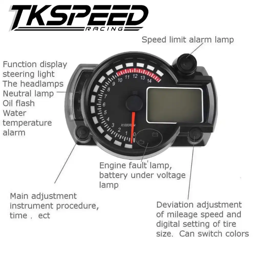
Motorcycle Speedometer With Fuel Gauge Wiring Diagram - Collection ...
PDF Fuel Pressure Gauge and Sensor Installation Instructions - Isspro • Dimmer - Connect the orange wire to the factory gauge dimmer circuit by either tapping into the in-cab fuse block or by connecting directly to the wire running from the dimmer on the headlight switch. 1 5 Figure 2: Connector. Pin Wire Color Function 1 Red Ignition 2 Orange Dimmer 3 Black Ground 4 Red/Yellow Sensor Power +5V
Moeller Fuel Gauge Wiring Diagram
Installing A Fuel Gauge and Sender | Hotrod Hotline This fuel level sender is designed to work in vented tanks with depths greater than 6-1/2 inches. Sender must be mounted perpendicular (not at an angle) from the top of the tank. Available in 240-33 & 0-90 ohm resistance ranges. You simply cut it to length and calibrate it for your application. Just make sure that it is compatible with your gauge.

Wiring Diagram For Fuel Gauge - 12
1973-1979 Ford Truck Wiring Diagrams & Schematics - FORDification.net 3727 x 2261 - 681 KB. Misc. Wiring Schematics & Diagrams. Checking windshield wiper switch continuity. 1979 F100-F350 intermittent wiper switch. Ford truck wire color and gauge chart.

How to Install an Air Fuel Gauge « Pro Street Online
How to install a Moeller fuel gauge - Jamestown Distributors Install your electric fuel sender, gently inserting float arm into tank followed by sending unit. Align screw holes between gasket, mounting plate and tank. Secure sending unit to tank, tightening mounting screws into place just until white sealant shows beneath the screw head. DO NOT OVER-TIGHTEN.
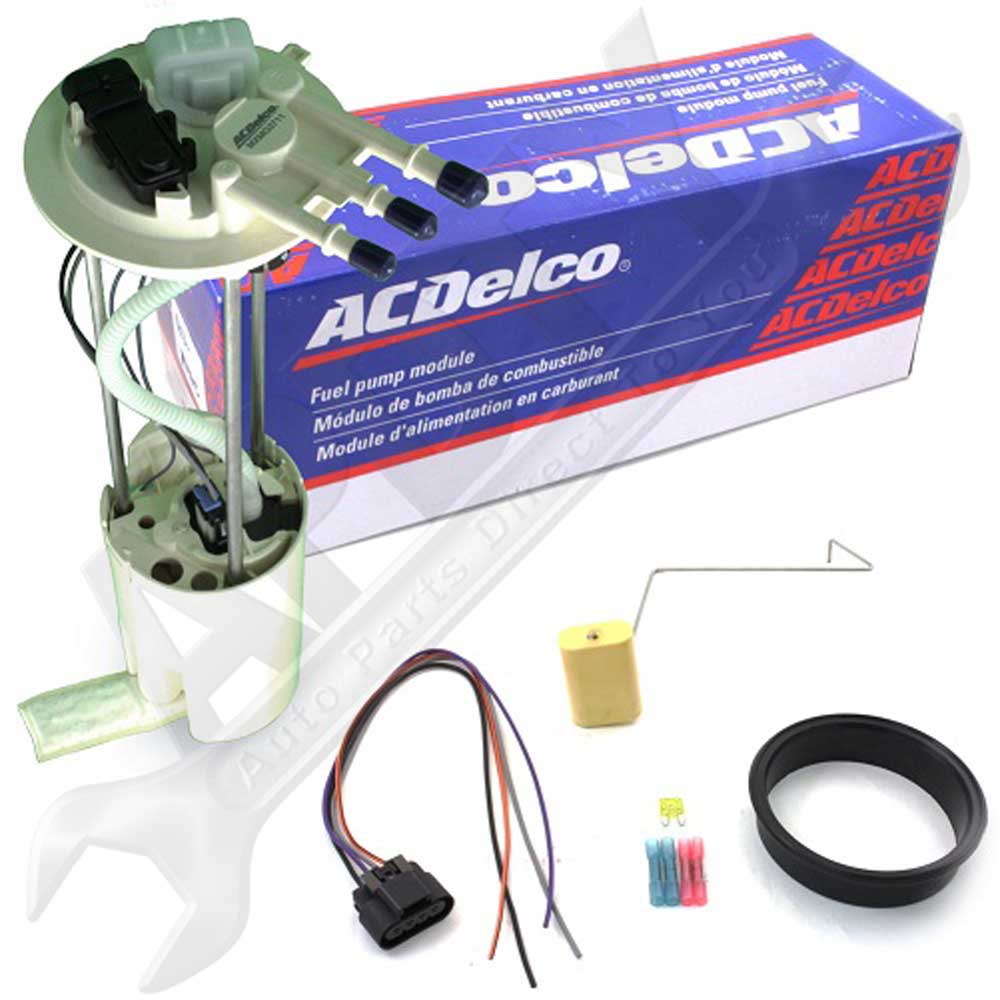
Atxe8397m Delphi New Fuel Pump Connector Color Wiring Diagram
Wiring Gauge Fuel FAST, ACCURATE AIR/FUEL DATA: AEM's world famous Wideband O2 UEGO Gauge is a must for anyone looking to maximize engine power and safety Assortment of fuel gauge sending unit wiring diagram Fuel Gauge Wiring 1) Always disconnect the vehicle battery before wiring any gauge Hi Beam Indicator Gray w/ Tracer Cluster Light Orange Right Turn/ Hazard Green Quadra-Trac/ 4wd Orange + Red Fuel Sender ...
Intermittent Fuel Gauge Stuck on Full: Fuel Gauge Pinned on Full ...
The Sending Unit - How Fuel Gauges Work | HowStuffWorks The Sending Unit The sending unit is located in the fuel tank of the car. It consists of a float, usually made of foam, connected to a thin, metal rod. The end of the rod is mounted to a variable resistor. A resistor is an electrical device that resists the flow of electricity. The more resistance there is, the less current will flow.

Fuel Gauge Wiring 2 - YouTube
› products › ignitionMSD 7730 MSD Power Grid System - Controller Only - Red The Power Grid Ignition System is the next evolution of our Programmable 7-Series Ignition Controls. The Grid incorporates an efficient 32 bit microcontroller and an all new software program, called MSD View, and is USB compatible. The Windows based software is designed with tabs to help racers easily select different programming windows and parameters. Also, the data acquisition files of the ...
0 Response to "44 universal fuel gauge wiring diagram"
Post a Comment