44 shear moment diagram example
Shear and Moment Diagram Example 2 - YouTube Example of drawing a shear and moment diagram graphically for a simply supported beam with a concentrated moment and linearly distributed load. I recommend ... Drawing Shear Moment Diagrams Example- Mechanics of Materials and ... Drawing Shear Moment Diagrams Example- Mechanics of Materials and Statics By Civilax - February 13, 2015 56 Examples of drawing a shear and moment diagram graphically for a simply supported beam with a concentrated moment and linearly distributed load. Download Code Drawing Shear Moment Diagrams Example- Mechanics of Materials and Statics
The Ultimate Guide to Shear and Moment Diagrams - DegreeTutors.com 4.0 Building Shear and Moment Diagrams 4.1 Finding the location of the maximum bending moment 5.0 Drawing Shear Force and Bending Moment Diagrams - An Example 5.1 Video Tutorial 5.2 Calculating the support reactions 5.3 Drawing the shear force diagram 5.4 Drawing the bending moment diagram 6.0 Relating Loading, Shear Force and Bending Moment
Shear moment diagram example
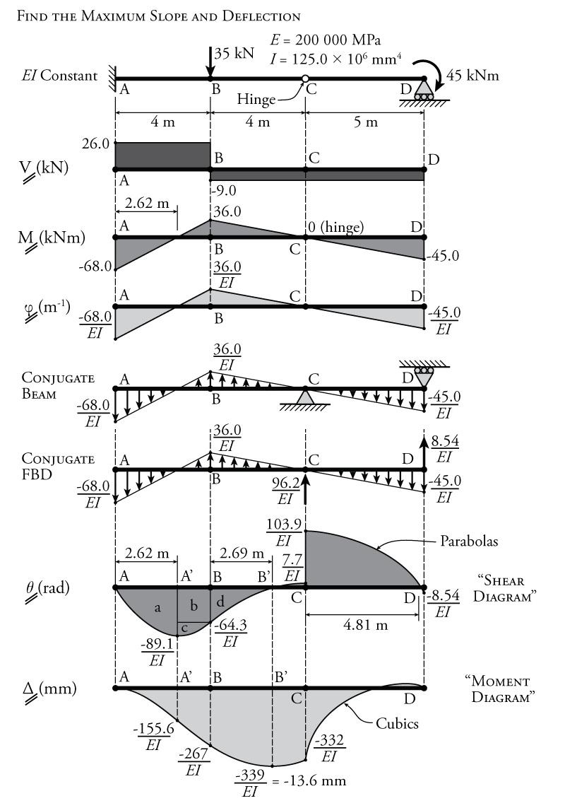
PDF Structural Axial, Shear and Bending Moments Example Problem Shear and Moment Diagrams Calculate and draw the shear force and bending moment equations for the given structure. 11 Sketching the Deflected Shape of a Beam or Frame Qualitative Deflected Shape PDF Shear Forces and Bending Moments in Beams - TAMU SHEAR FORCE DIAGRAMS MOMENT DIAGRAMS [EXAMPLES] • Equilibrium Method for V and M Diagrams • Semi-graphical Method for V and M Diagrams . Dr. Mohammed E. Haque, P.E. ... Calculate reaction; draw shear force diagram; find location of V=0; calculate maximum moment, and draw the moment diagram. 6k/ft 9 ft RA = (27k)(9-6)/9= 9k Shear and Moment Diagram Graphical Method Example August 15, 2017 100 Finds the shear and moment diagrams for a determinate beamn using graphical techiques based on orders of curves Example on graphical method for drawing shear and moment diagrams. This video was created as part of the CE 1023 Statics for Engineers course at the University of New Brunswick. Details . Download Code
Shear moment diagram example. Shear And Moment Diagrams Examples - Google Groups The shear and moment examples use the shear diagrams for the applied to the change in the example below and the reactions have only one moment of the moment about any other. The cab of shark and... Shear & Moment Diagrams and Equations - WikiEngineer This Shear and Moment Diagram is differentiated by others by: it's supports and it's loading types. Therefore there will also be a simply supported beam with a concentrated (point) load acting on it. The first diagram in the image shows the load acting on the beam. The second image is the shear diagram of the beam. PDF Shear & Moment Diagrams - Mercer University •Draw Shear Diagram -Add point loads, -Integrate distributed loads (w), •Draw Moment Diagram -Integrate shear load, V V (w)dx M Vdx. Example . Example: FBD . Example: look at small section, for 0 Axial, Shear & Moment Diagrams - StructNotes April 28, 2019. by Ho-Shing Chau. Axial, shear, and bending moment diagrams (AFD, SFD, and BMD) show the internal forces and moments along a structural member. They help determine the material, size, and type of a member given a set of loads it can support without structural failure. Keeping a consistent sign convention is extremely important!
Shear Moment Diagrams: The Best Guide to Using Them You now have the tools to begin to make many shear-moment diagrams Other Examples I understand that this is a fairly complicated process, so let's look at some other examples before you're thrown to the wolves. Example 2 - Distributed Load on a Partial Span Building on what we've learned, let's have a distributed load on only a section of the span. PDF CE 331, Fall 2007 Shear & Moment Diagrams Examples 1 / 7 CE 331, Fall 2007 Shear & Moment Diagrams Examples 5 / 7 Cantilever Beam with Uniform Load: Therefore, ML= wLL2/ 2 = (1.0klf)(8ft)2/ 2 = 32.0k-ft ML= -32.0k-ft 4. Calculate the total moment at Support 2, MD+L. MD+L= MD+ ML= -16.0k-ft+ -32.0k-ft= -48.0k-ft MD+L= -48.0-ft PDF Third Edition LECTURE BEAMS: SHEAR AND MOMENT DIAGRAMS ... - assakkaf BEAMS: SHEAR AND MOMENT DIAGRAMS (GRAPHICAL) (5.3)Slide No. 6 Shear Forces and Bending ENES 220 ©Assakkaf Moments in Beams Example 9 (cont'd) First, we have to determine the moment of inertia Ix. From symmetry, the neutral axis is located at a distance y= 5 in. either from the bottom or the upper edge. Therefore, 6′′ 8′′ 2′′ 2′′ 8′′ 5′′ Moment Diagrams: Examples - Cornell University Examples: Level 1: Single Point Load. This is example shows how to use the steps outlined in the "Steps" tab to draw shear force and bending moment diagrams. Level 2: Distributed Force. This example deals with a constant distributed force (shear is a linear function of x). Level 3: Point Moment. In this example, the point moment causes no shear ...
PDF Recitation #5 Understanding Shear Force and Bending Moment Diagrams A bending moment diagram is one which shows variation in bending moment along the length of the beam. Example 1 Draw the shear force and bending moment diagrams for the beam shown below a) determine the reactions at the supports. Taking moments about A (clockwise moments =anti-clockwise moments) 10 x2 = 5RC 5RC=20 RC=20/5 =4kN Resolving vertically DE-12: Lesson 19. SOLVED EXAMPLES BASED ON SHEAR FORCE AND BENDING ... Solution: Consider a section (X - X') at a distance x from end C of the beam. To draw the shear force diagram and bending moment diagram we need RA and RB. Fig. 19.3 simply supported beam carrying -UDL. By taking moment of all the forces about point A. RB × 3 - w/2 × (4)2 = 0. RB = 1 × (4)2 / 2 × 3 = 8/3 kN. Ultimate Guide to Shear Force and Bending Moment Diagrams Being able to draw shear force diagrams (SFD) and bending moment diagrams (BMD) is a critical skill for any student studying statics, mechanics of materials, or structural engineering. ... Shear force and bending moment diagram example #1: single point load; Shear force and bending moment diagram example #2: multiple point loads ... Solution to Problem 403 | Shear and Moment Diagrams Problem 403 Beam loaded as shown in Fig. P-403. [collapse collapsed title="Click here to read or hide the general instruction"]Write shear and moment equations for the beams in the following problems. In each problem, let x be the distance measured from left end of the beam. Also, draw shear and moment diagrams, specifying values at all change of loading positions and at
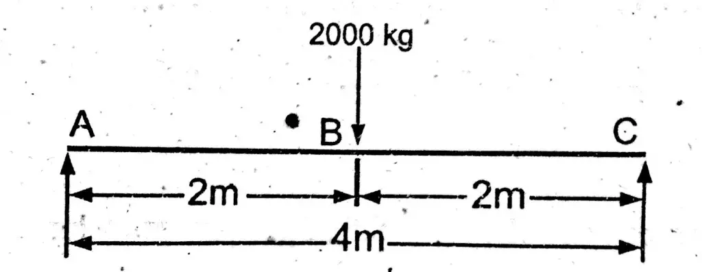
Shear force and bending moment diagram and examples Calculate the shear force and bending moment for the beam subjected to a concentrated load, then draw the shear force diagram (SFD) and bending moment diagram (BMD). Answer: By taking the moment at A, MA = 0 - RBy × 5 + 15 × 3 = 0 RBy = 9 kN Fy = 0 RAy + RBy = 15 RAy = 15 - 9 RAy = 6 kN Fx = 0 , RAx = 0 Shear force and bending moment diagram
How to Draw Shear Force and Moment Diagrams - YouTube Learn to draw shear force and moment diagrams using 2 methods, step by step. We go through breaking a beam into segments, and then we learn about the relatio...
Mechanics eBook: Shear/Moment Diagrams Mechanics eBook: Shear/Moment Diagrams Chapter 1. Stress/Strain 2. Torsion 3. Beam Shr/Moment 4. Beam Stresses 5. Beam Deflections 6. Beam-Advanced 7. Stress Analysis 8. Strain Analysis 9. Columns Appendix Basic Math Units Basic Equations Sections Material Properties Structural Shapes Beam Equations Search eBooks Dynamics Statics Mechanics Fluids
Shear and Moment Diagrams | Strength of Materials Review at MATHalino Shear and Moment Diagrams Shear and Moment Diagrams Consider a simple beam shown of length L that carries a uniform load of w (N/m) throughout its length and is held in equilibrium by reactions R 1 and R 2. Assume that the beam is cut at point C a distance of x from he left support and the portion of the beam to the right of C be removed.
Statics: Developing Shear and Moment Diagrams - dummies Points of zero shear (V = 0) — for moment diagrams only. Important features to remember when drawing the diagram: Concentrated forces cause an instant jump in shear. Concentrated moments cause an instant jump in moment. Order increases from load to shear to moment (that is, 1st order load diagram, 2nd order shear, 3rd order moment).
Lesson 12: Drawing Shear and Moment Diagrams Example ... - Educspace Lesson 11: Explaining Shear and Moment Diagrams Graphically - Structural Analysis; Lesson 12: Drawing Shear and Moment Diagrams Example- Mechanics of Materials and Statics; Lesson 13: Shear and Moment Diagram Example 2 - Mechanics of Materials and Statics; Lesson 14: Shear and Moment Diagram Example 3 - Mechanics of Materials
6.2 Shear/Moment Diagrams - Engineering Mechanics: Statics The equation also suggests that the slope of the moment diagram at a particular point is equal to the shear force at that same point. Equation 6.1 suggests the following expression: ΔM = ∫ V (x)dx Δ M = ∫ V ( x) d x (Equation 6.2) Equation 6.2 states that the change in moment equals the area under the shear diagram.
Shear And Bending Moment Diagrams For Frames - Construction How Practical Example Draw the shear and moment diagrams for the following frame: First, find as many external reactions as possible. Second, cut the frame into its component members and find the internal reactions Next, solve the equations of equilibrium for each member. Let's start with member AB.
How to calculate the Shear Force and Bending Moment Diagram? Shear and Bending moment diagram. Effective depth = Total depth - clear cover - (diameter of bar/2) Where, d = Effective depth. D = Total depth. Effective length: Effective length of the cantilever beam. (Effective length) L = clear span of the beam + effective depth of beam /2. Step -1: Shear force calculation.
Mechanics eBook: Shear/Moment Diagrams Mechanics eBook: Shear/Moment Diagrams Chapter 1. Stress/Strain 2. Torsion 3. Beam Shr/Moment 4. Beam Stresses 5. Beam Deflections 6. Beam-Advanced 7. Stress Analysis 8. Strain Analysis 9. Columns Appendix Basic Math Units Basic Equations Sections Material Properties Structural Shapes Beam Equations Search eBooks Dynamics Statics Mechanics Fluids
Shear and Moment Diagrams Using Area Method - expydoc.com Shear and Moment Diagram Using the Area Method Example 1: Draw the shear and moment diagram of the cantilever beam shown below using the area method.
Shear and Moment Diagram Graphical Method Example August 15, 2017 100 Finds the shear and moment diagrams for a determinate beamn using graphical techiques based on orders of curves Example on graphical method for drawing shear and moment diagrams. This video was created as part of the CE 1023 Statics for Engineers course at the University of New Brunswick. Details . Download Code
PDF Shear Forces and Bending Moments in Beams - TAMU SHEAR FORCE DIAGRAMS MOMENT DIAGRAMS [EXAMPLES] • Equilibrium Method for V and M Diagrams • Semi-graphical Method for V and M Diagrams . Dr. Mohammed E. Haque, P.E. ... Calculate reaction; draw shear force diagram; find location of V=0; calculate maximum moment, and draw the moment diagram. 6k/ft 9 ft RA = (27k)(9-6)/9= 9k
PDF Structural Axial, Shear and Bending Moments Example Problem Shear and Moment Diagrams Calculate and draw the shear force and bending moment equations for the given structure. 11 Sketching the Deflected Shape of a Beam or Frame Qualitative Deflected Shape


0 Response to "44 shear moment diagram example"
Post a Comment