43 in a data flow diagram, external entities are represented by:
The Context Diagram and Data Flow Diagram | Tasstudent.com Oct 15, 2015 · There are only three symbols used in a context diagram: A circle to represent the system in terms of a single process. There will never be more than a single process in any context diagram, arrows to represent data flow, and a rectangle to represent any external entities affecting the system. There can be numerous external entities. Elements of data-flow diagrams - University of Cape Town External entities are represented on the diagram as ovals drawn outside of the system boundary, containing the entity name and an identifier. Figure 6.5. Notation for external entities Names consist of a singular noun describing the role of the entity. Above the label, a lower case letter is used as the identifier for reference purposes.
What is a Data Flow Diagram - Lucidchart External entity: an outside system that sends or receives data, communicating with the system being diagrammed. They are the sources and destinations of information entering or leaving the system. They might be an outside organization or person, a computer system or a business system. They are also known as terminators, sources and sinks or actors.

In a data flow diagram, external entities are represented by:
Data Flow Diagrams | Enterprise Architect User Guide Data Flow Diagrams. These diagrams show how data flows through an information system, which processes or external entities create or consume the data, and where it is stored. They do not detail the sequencing between processes, which would be represented by process models. Enterprise Architect provides a Data Flow diagram that modelers can use ... What is DFD(Data Flow Diagram)? - GeeksforGeeks The flow of data of a system or a process is represented by DFD. It also gives insight into the inputs and outputs of each entity and the process itself. DFD does not have control flow and no loops or decision rules are present. Specific operations depending on the type of data can be explained by a flowchart. Data Flow Diagram (DFD) Conceptual Study | Free Essay Example A data flow diagram can be defined as a diagrammatic procedure that represents external entities, logical storage, and where data flows in a system. DFD is instrumental in operational systems where a function may be of great significance and more complex compared to how the system can be manipulated. DFD was first applied in the software ...
In a data flow diagram, external entities are represented by:. What is Data Flow Diagram (DFD)? How to Draw DFD? An external entity can represent a human, system or subsystem. It is where certain data comes from or goes to. It is external to the system we study, in terms of the business process. For this reason, people used to draw external entities on the edge of a diagram. Process System context diagram - Wikipedia Decision trees and data storage are represented in system flow diagrams. A context diagram can also list the classifications of the external entities as one of a set of simple categories [5] (Examples: [6] ), which add clarity to the level of involvement of … Notation of Data Flow Diagrams - EDUCBA A data flow diagram is basically denoted by using numerical symbols like circles, arrows, rectangles to categorize input data, output result, and the directions through which data is flowing in the entire process structure. ... The external entities are drawn over the edges of the diagram. Process notation: It is represented using bubbles where ... Data Flow Diagram (DFD) Symbols - EdrawMax - Edrawsoft 18/02/2022 · Before you embark on creating a data flow diagram, it is important to determine what suits your needs between a physical and a logical DFD. Physical DFD focuses on how things happen by specifying the files, software, hardware, and people involved in an information flow.. Logical DFD focuses on the transmitted information, entities receiving the information, …
What are the levels of data flow diagram? - ins.jodymaroni.com Data Flow Diagrams DFD Levels DFD are numbered beyond. ... (level 0 DFDs) are diagrams where the whole system is represented as a single process. A level 1 DFD notates each of the main sub-processes ... All data flow diagrams include four main elements: entity, process, data store and data flow. External Entity - Also known as actors, sources ... What is a Data Flow Diagram (DFD)? - TechTarget Select the interests involved and categorize them into external entities, flows, processes and stores. Illustrate a Level 0 context diagram with basic connections. Create more detailed Level 1 diagrams that branch off the processes of the context diagram, including connected flows, stores, additional processes and external entities. PDF Chapter 6. Data-Flow Diagrams - University of Cape Town • Describe the meaning of the symbols used in data-flow diagrams. • Describe the generic framework activities at which data flow diagrams can be used and the corresponding roles of data-flow diagrams in these stages. • Construct simple data-flow diagrams from a textual description. • Construct a levelled set of data-flow diagrams. What Is a Data Flow Diagram and How To Make One? - Venngage A data flow diagram is typically organized hierarchically, showing the entire system at one level, followed by major subsystems at the next. Finally, details are shown for each primary subsystem, with components identified last. Here's an example, which details the flow of customer data through the different layers of a business transaction.
Data Flow Diagram - an overview | ScienceDirect Topics A Data Flow Diagram (DFD) is a graphical representation of the “flow” of data through an information system (as shown on the DFD flow chart Figure 5), modeling its process aspects.Often it is a preliminary step used to create an overview of the system that can later be elaborated. DFDs can also be used for the visualization of data processing (structured design) … Data Flow Diagram: A Comprehensive Guide - Zen Flowchart An external entity, also known as terminators, sources, sinks, or actors, is an outside process where information enters or leaves the system. It acts as the source and the destination of the information. Thus, it is usually placed at the edge of the diagram. External entities can either be a person, an organization, or a computer system. Levels in Data Flow Diagrams (DFD) - GeeksforGeeks It's designed to be an abstraction view, showing the system as a single process with its relationship to external entities. It represents the entire system as a single bubble with input and output data indicated by incoming/outgoing arrows. 1-level DFD: In 1-level DFD, the context diagram is decomposed into multiple bubbles/processes. Data Flow Diagram, workflow diagram, process flow diagram Data Flow Diagram consists of the following components: Processes and functions which represent actions that happened in the information system; External entities which represent in the system data ingoing and outgoing from it; Data depositories which represent places in the system where data can be saved for a definite period of time;
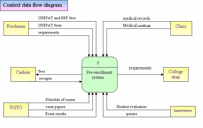
Narration: DFD of USEP Pre-enrollment System
Data Flow Diagram Comprehensive Guide with Examples Therefore, add an External Entity to diagram and name it Customer. Like creating process, you can create an external entity by dragging External Entity from diagram toolbar to diagram. A data flow is used to represent the movement of data between different parts of the system. In this case, "order" is a data created by customer and ...

26 Data Flow Diagram Level 1 - Wiring Database 2020
Data Flow Diagram: Examples (Context & Level 1), Explanation, Tutorial External entities are outside systems such as people (customers, stakeholders, managers), organizations, computers and other systems that send or receive data from our system. Data stores - places where data is held such as files or repositories. Data stores show information that is not moving.
In A Data Flow Diagram External Entities Are Represented By ...
Data-flow diagram - Wikipedia A data-flow diagram is a way of representing a flow of data through a process or a system (usually an information system).The DFD also provides information about the outputs and inputs of each entity and the process itself. A data-flow diagram has no control flow — there are no decision rules and no loops. Specific operations based on the data can be represented by a flowchart.
PPT - SE: CHAPTER 4 Capturing the Requirements PowerPoint Presentation ...
Components of Data Flow Diagrams - Enterprise Software External entities are components that interact with a business process on the DFD but fall outside of the boundaries of the DFD. External entities can be: · initiators of data (i.e., spontaneous generators) flowing into the business process. · end recipients of data (i.e., data sinks) flowing from the business process.

Data Flow Diagram: A Practical Guide — Business Analyst Learnings
Elements of Data Flow Diagrams - External Entties, Processes, Data Flow ... Elements of Data Flow Diagrams Data Flow Diagrams are composed of the four basic symbols shown below. The External Entity symbol represents sources of data to the system or destinations of data from the system. The Data Flow symbol represents movement of data. The Data Store symbol represents data that is not moving (delayed data at rest).

Data Flow Diagrams | Enterprise Architect User Guide
Data Flow Diagram for Hospital Management System This is also called as context diagram for hospital management system in which entire system is represented as single process with its relationship with external entities such as admin, staff, doctor etc. In this data flow diagram, you will see the general process done during healthcare management. First Level Data Flow Diagram (Level 1 DFD) of ...

In A Data Flow Diagram External Entities Are Represented By - General ...
Data Flow Diagram Symbols | Lucidchart A general overview of a system is represented with a context diagram, also known as a level 0 DFD, which shows a system as a single process. A level 1 diagram provides greater detail, focusing on a system’s main functions. ... Choose the symbols you need from our library—processes, data stores, data flow, and external entities—and drag ...

In A Data Flow Diagram External Entities Are Represented By ...
What is difference between data flow diagram and flowchart? There are four basic elements of a data flow diagram: processes, data stores, external entities, and data flows. The picture below shows the standard shapes for both methodologies. Also to know, what is a data flow diagram used for? Also known as DFD, Data flow diagrams are used to graphically represent the flow of data in a business ...
0 Response to "43 in a data flow diagram, external entities are represented by:"
Post a Comment