43 fe c phase diagram
FE-O-C System Diagrams - ResearchGate I have one question related to FE-O-C system diagrams, Basically I want to draw these diagrams. I have the reaction rate constant for all reactions for this FE-O-C system at the different... IRON-CARBON EQUILIBRIUM DIAGRAM | Engineers Gallery Cementite is a chemical compound of carbon with iron and is known as iron carbide (Fe3C). Cast iron having 6.67% carbon is possessing complete structure of cementite. Free cementite is found in all steel containing more than 0.83% carbon. It increases with increase in carbon % as reflected in Fe-C Equilibrium diagram. It is extremely hard.
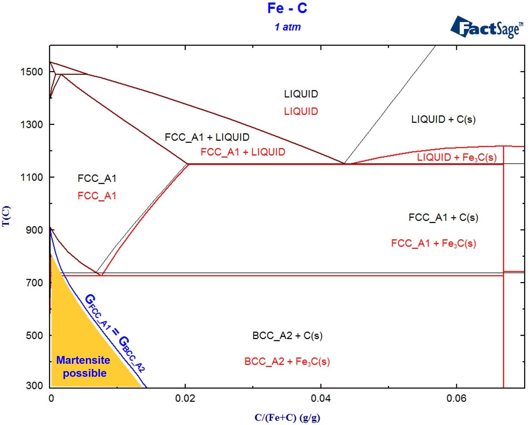
Thermodynamic description of the Fe-Cu-C system - ScienceDirect In the present study, the Fe-C phase diagram is optimized on the basis of Gustafson's results [10]. Therefore, only the parameters of the liquid phase were slightly modified, while those of the fcc and bcc phases remain the same as Gustafson's [10]. As for the metastable phase, optimized results by Göhring [17] were adopted.
Fe c phase diagram
PDF Chapter 9: Fe-C system - University of Washington (Fe-C System) C 0.76 Adapted from Fig. 9.30,Callister 7e. pearlite proeutectoid ferrite 100 µm Hypoeutectoid steel R S ... • Phase diagrams are useful tools to determine: --the number and types of phases, --the wt% of each phase, --and the composition of each phase Ellingham diagram - Wikipedia An Ellingham diagram is a graph showing the temperature dependence of the stability of compounds. This analysis is usually used to evaluate the ease of reduction of metal oxides and sulfides.These diagrams were first constructed by Harold Ellingham in 1944. In metallurgy, the Ellingham diagram is used to predict the equilibrium temperature between a metal, its oxide, … phase diagram iron carbon | Metallurgy for Dummies The cast iron portion of the Fe-C phase diagram covers the range between 2.08 and 6.67 wt. % C. The steel portion of the metastable Fe-C phase diagram can be subdivided into three regions: hypoeutectoid (0 < wt. % C < 0.68 wt. %), eutectoid (C = 0.68 wt. %), and hypereutectoid (0.68 < wt. % C < 2.08 wt. %).
Fe c phase diagram. PDF APPLICATIONS OF Fe-C PHASE DIAGRAM T-T-T Diagram Figure 5-7 Isothermal transformation diagram (T-T-T diagram) for eutectoid composition steel. Structures resulting from transformation at various temperatures are shown as insets. (Courtesy of United States Steel Corp., Pittsburgh, PA.) Iron-Carbon Equilibrium Diagram | Metallurgy The ability to interpret this diagram is important for proper appreciation of phase changes. Fe-C diagram actually provides a valuable foundation on which to build knowledge of large variety of both plain carbon and alloy steels. Conventionally, the complete Fe-C diagram should extend from 100% Fe to 100% carbon, but it is normally studied up ... What is the Iron-Carbon Phase Diagram? - Engineering Choice The Fe - C diagram (also called the iron-carbon phase or equilibrium diagram) is a graphic representation of the respective microstructure states of the alloy iron-carbon (Fe-C) depending on temperature and carbon content. To explain this diagram, an introduction about metal structures and pure iron must be done. Why is the beta phase not shown on the Fe-C phase diagram? Consider the most conventional 2D phase diagram where temperature is plotted along the y axis and composition of carbon along the x axis. Phases are mapped on the phase diagram if they are...
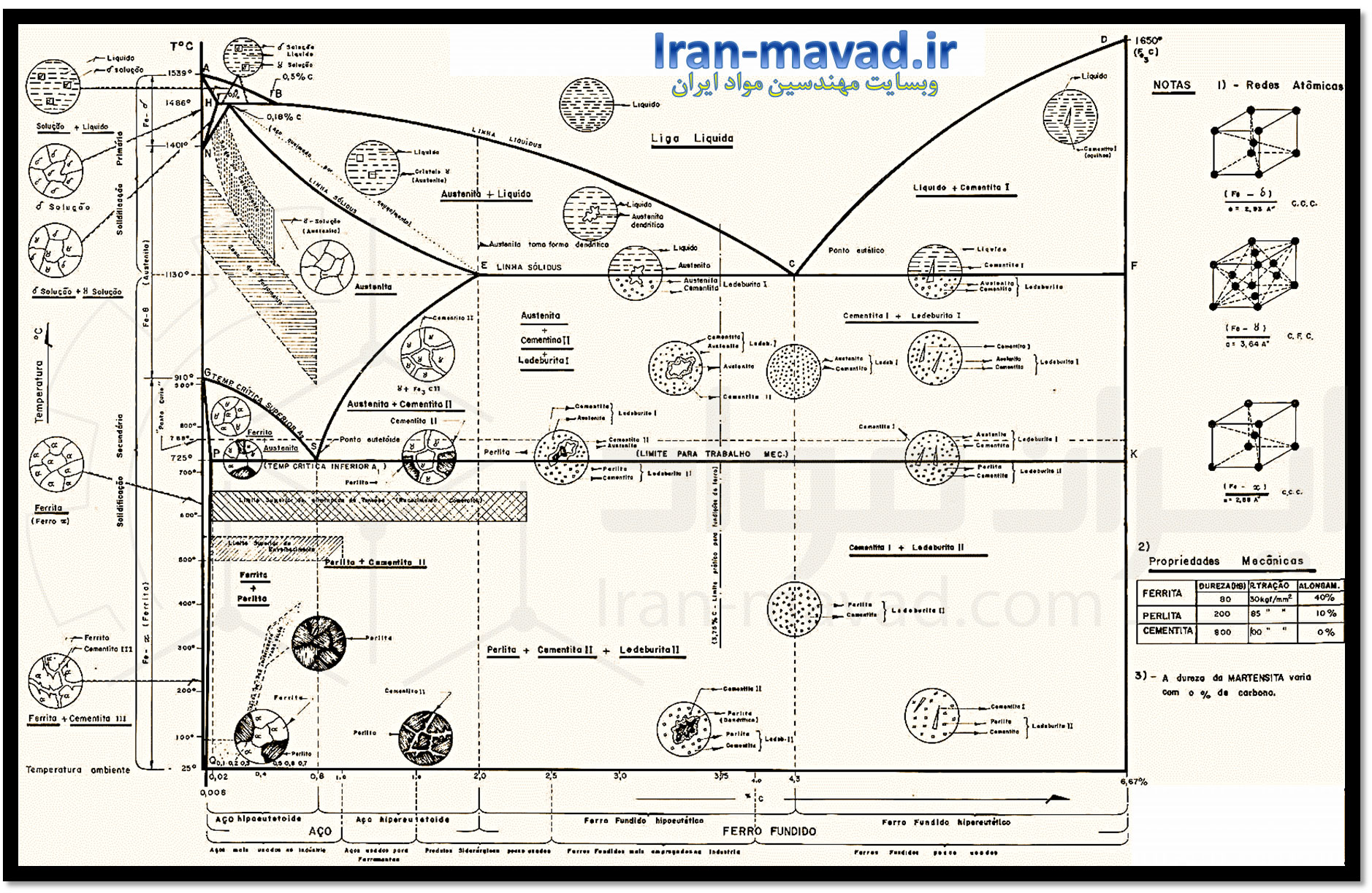
PDF The C-Fe (Carbon-Iron) System - gotrawama.eu Earlier literature on the Fe-C system was listed in a review article by [36Eps]. [I-lansen] covered information published prior to 1955. A review in [Metals], with the Fe-C phase diagram based primarily on [72Chi], has been sewing as one of the standard Fe- C phase diagrams until now. However, [79Agr] and [84Oht] PDF Iron-Iron carbide (Fe-Fe C) Phase Equilibrium Diagram The diagram shows the phases present at various temperatures for very slowly cooled Fe-C alloys with carbon content up to 6.67%. Information given by the diagram: 1. Solid phases in the phase diagram 2. Invariant reactions in the phase diagram 3. Critical temperatures 4. Eutectoid, hypoeutectoid and hypereutectoid steels 1. (PDF) Fe-C Phase Diagram | Bogdan Chiriac - Academia.edu • on the right the phase diagram only extends to 6.70 wt%c • at this concentration the intermediate compound iron carbide, or cementite (fe3c) is formed • this is sufficient to describe all of the fe3c steels and cast irons pure fe cementite used today. 6.70 wt% 3 c development of microstructures in iron-carbon alloys γ • … Melting phase relations in Fe–Si–H at high pressure and … 15/06/2022 · Coexisting Fe–Si–H liquid and solid fcc FeH and B2 Fe–Si phases at 48 GPa and 2100 K in run #4 using Fe–Si and C n H 2n+2 paraffin as starting materials.
Ternary Phase Diagram - an overview | ScienceDirect Topics 2.3.5.5.3 Fe–C–S System. Ohtani and Nishizawa calculated the Fe–C–S ternary phase diagram on the basis of the thermodynamic analysis of Fe–C and Fe–S and Fe–C–S ternary melts [203]. The Gibbs free energy of individual phases was approximated by the interstitial solution model, assuming both C and S to be interstitial atoms. Example T_03 - Fe-C Phase Diagram - YouTube Learn two simple ways to calculate a binary phase diagram in the Fe-C system using the graphical mode of Thermo-Calc. ~~TIMESTAMPS~~0:00 Intro0:42 How to cal... The iron-iron carbide (Fe-Fe3C) phase diagram Review Fe-C phase diagram • 2 important points-Eutectoid (B): γ⇒α+Fe 3C-Eutectic (A): L ⇒γ+Fe 3C Fe 3 C (cementite) 1600 1400 1200 1000 800 600 400 0 12 3 4 5 66.7 L γ (austenite) γ+L γ+Fe 3C α+Fe 3C α + γ L+Fe 3C δ (Fe) C o, wt% C 1148°C T(°C) α 727°C = Teutectoid A R S 4.30 Result: Pearlite = alternating layers of αand Fe ... Solved Given the Fe-C phase diagram and answer question 1 - Chegg Given the Fe-C phase diagram and answer question 1 - 4. 1. (5 pts) What is the eutectic composition of carbon for the Iron-Carbon phase diagram? 2. (5 pts) Martensite steels are the hardest and strongest, yet most brittle a) True b) False. 3. Consider austenite containing 0.65 wt% C, cooled to just below 727°C.
Example for a FactSage calculation of a non-equilibrium process - GTT ...
Iron-Carbon Diagram Explanation [PDF] - Mechanical E-Notes Iron-Carbon Phase Diagram with Detailed Explanation: If the percentage of the carbon is in the range of 0 to 2.11 % then it is called Steel and if the percentage of carbon is in the range of 2.11 to 6.67% then it is called Cast iron. As the carbon content increases, it produces more Iron-Carbide volume and that phase will exhibit high hardness.
فیلم دیاگرام آهن کربن - نمودار تعادلی
Thermodynamic description of the Fe-Cu-C system - ScienceDirect Fe-C binary system. In the present study, the Fe-C phase diagram is optimized on the basis of Gustafson's results [10]. Therefore, only the parameters of the liquid phase were slightly modified, while those of the fcc and bcc phases remain the same as Gustafson's [10]. As for the metastable phase, optimized results by Göhring [17] were ...
FactSage.cn - 相图
Santa Fe Institute - Wikipedia The Santa Fe Institute (SFI) is an independent, nonprofit theoretical research institute located in Santa Fe, New Mexico, United States and dedicated to the multidisciplinary study of the fundamental principles of complex adaptive systems, including physical, computational, biological, and social systems.The institute is ranked 24th among the world's "Top Science and …

Fe Fe3c Phase Diagram - Free Wiring Diagram
PDF Fe-C Phase Diagram - University of Babylon Fe-C Phase Diagram 1 Fe-C Phase Diagram 2 • At room temperature it exists as ferrite, or αiron. • Upon heating pure Iron experiences two changes in crystal structure. • When we heat it to 912°C it experiences a polymorphic transformation to austenite, or γiron • At 1394°C austenite reverts back to a BCC phase called δferrite. 1394°C δFerrite BCC
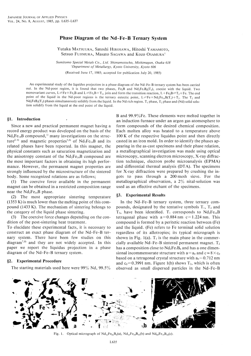
(PDF) Phase Diagram of the Nd-Fe-B Ternary System
PDF The Iron Carbide (Fe Fe3C) Phase Diagram - الرئيسية C Phase Diagram ¾α‐ferrite‐solid solution of C in BCC Fe •Stable form of iron at room temperature. • Transforms to FCC g‐austenite at 912 °C ¾γ‐austenite‐solid solution of C in FCC Fe • Transforms to BCC δ‐ferrite at 1395 °C •Is not stable below the eutectic temperature (727 °C)
![Diagram Fasa Fe-C - [PDF Document]](https://static.fdocument.org/img/1200x630/reader020/image/20190920/5571ffa549795991699dc188.png?t=1615342828)
Diagram Fasa Fe-C - [PDF Document]
Fe-C phase diagram.pptx - LECTURE NOTES S3 MTG - Physical... Lecture No: 27 Submitted by: Siva Prasad M No. of Period: 2 Date: 29 Sep Objective: - To draw Fe-C equilibrium diagram, to study eutectic, eutectoid steels, to know the difference between steel and cast iron, to study the fundamentals of heat treatment of steel, Al-Si diagram, Al-Mg diagram, Mg-Si diagram. Key words:-Fe-C diagram, eutectic steel, eutectoid steel, pearlite, leduberite etc..

PHASE DIAGRAM - University of Engineering and Technology ...web. · γ ...
The Iron-Carbon Alloys And Fe-C Phase Diagram - ML - Engineering Iron-Carbon (Fe-C) phase diagram. The iron-carbon phases and phase diagram is slightly complex, compared with other diagrams. The horizontal axis of the Fe-C diagram shows the percentage of carbon inside the Fe-C systems. The solubility limit of carbon inside the iron is very low.

Tin/Lead Binary Phase Diagram for Solder | My Style | Pinterest
Fe-C phase diagram - Solid State Chemistry @Aalto - Aalto University Wiki How to interpret phase diagrams. Figure 1. Example of a binary phase diagram for arbitrary materials A and B (Figure: Nikita Bobrov). The typical binary (system of two materials) phase diagram is shown in Figure 1. Typically, it consists of various regions: the α + β region shows the case where both α and β phases of materials A and B ...
0 Response to "43 fe c phase diagram"
Post a Comment