40 bremas boat lift switch wiring diagram
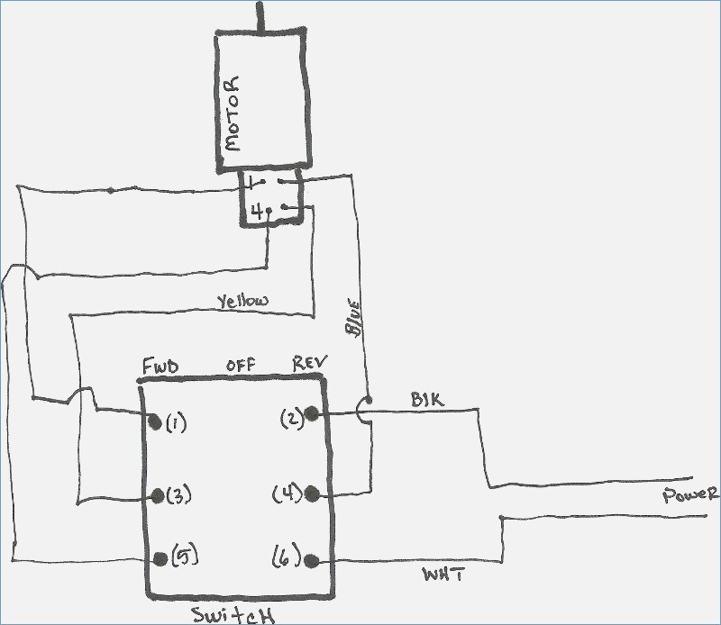
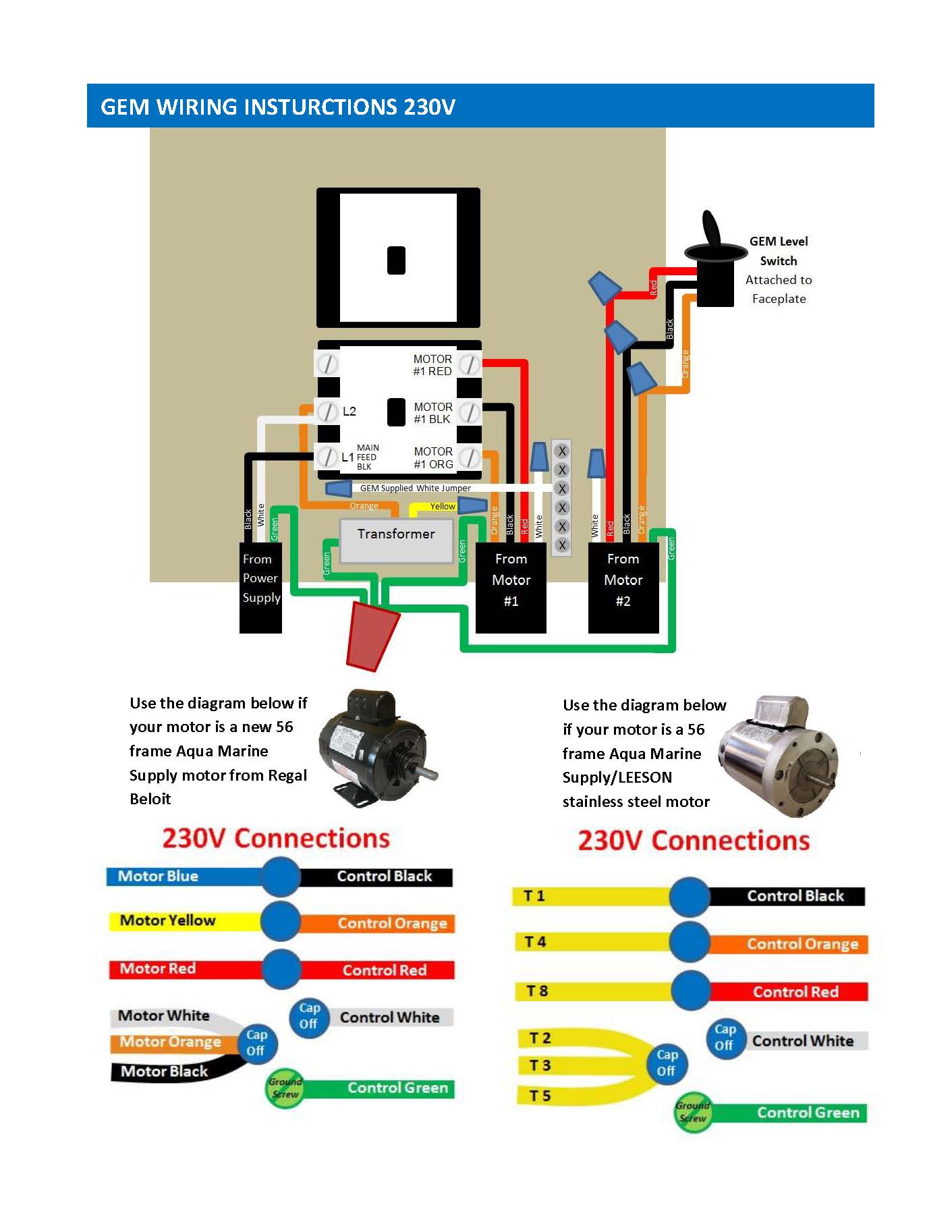
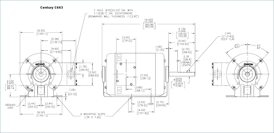
Boat Lift Switch Wiring Diagram - need 3 4 hp replacement lift motors ... Saturday, July 2, 2022 bremas boat lift switch wiring diagram sample Boat Lift Switch Wiring Diagram. Here are a number of highest rated Boat Lift Switch Wiring Diagram pictures on internet. We... I'm trying to wire bremas switches to a Dayton 6k719 motor… Let me pull up the diagrams for the switch and motor and I will post back shortly for you. Ok this was kind of a tough one since the new motor is a different configuration. Unfortunately you will need a new cable between the switch and motor - one that has an additional wire.. I am attaching a diagram. Bremas...png
diagramweb.net › gravely-zero-turn-mower-beltGravely Zero Turn Mower Belt Diagram Nov 30, 2018 · Economaster Em3727 Wiring Diagram; 2007 Lexus Es350 Fog Light Wiring Diagram; Husqvarna Yth2448 Belt Diagram; E-z-go Txt Gas Golf Cart Wiring Diagram; Renix Xj Wiring Diagram; Bremas Boat Lift Switch Wiring Diagram; Hunter Model 59039 Wiring Diagram; Eagle Liftgate Wiring Diagram; Memphis Audio Prx570c Wiring Diagram; Squier Affinity Telecaster ...
Bremas boat lift switch wiring diagram
Brema Cb425 - ijsblokjesmachine brema cb 246 bij ons scherp in prijs ... [Brema Cb425] - 15 images - brema products in pakistan pakeeza commercial kitchen, version 2 brema c23377, 44kg cb416 brema, pieces brema serie cb, Position Rotary 4 Wiring Diagram Switch - wkz.per.me.it maybe these wiring diagrams will help universal wiper switch wiring diagram of wire (59:1 gear ratio) limit switch (included) provides end of travel stop (1) water-resistant transmitter - up to 300 ft rotation direction switch is set to this position, the actuator internally switches the rotation direction control signals as stated in section … Switch Wiring Diagram Position 4 Rotary - etu.uds.fr.it make the 4 suspender through the 4 hanger of the main body to suspend it it assortment of 4 position rotary switch wiring diagram white puzzle pieces pictured above are two single pole double throw (spdt) switch diagrams a wiring diagram is a streamlined conventional pictorial representation of an electric circuit to section c1 and c2 to section …
Bremas boat lift switch wiring diagram. 4 Diagram Switch Rotary Position Wiring - ufs.uds.fr.it The M1150 has many of the features found on its powerful com- 5 out of 5 stars 5 $6 Here is the original rotary switch from the mill Boat switch panel with marine-grade rocker switches and rubber seal-cap to keep it water-tight The common light switch used in household wiring is an example of a toggle switch The common light switch used in ... Position Wiring Switch Rotary Diagram 4 the following diagram shows the rotary encoder waveform output on pins a and b (clk) and (dt) respectively * the ignition switch is most commonly powered from the starter battery stud, but source may vary depending on application wire the new single-pole switch this is a switchable shorting jack 3-way, 4 position, 2 circuit rotary switch with … Diagram Wiring Switch Rotary 4 Position - noc.sintesi.to.it Search: 4 Position Rotary Switch Wiring Diagram. The momentary switch must have a minimum contact rating of 1 FLA, IO LRA at 115 volts AC If you need help setting the address switches, see the brain user's guide 5 out of 5 stars 5 $6 Reaction score 158 Also, the switch toggle lever on a three-way does not have the ON-OFF markings found on a single-pole switch Also, the switch toggle lever on ... Position Diagram Wiring Switch Rotary 4 - pvo.atcm.modena.it HOW TO USE THIS WIRING DIAGRAM 50- o WIRING COLOR CODE Wiring color code is indicated with alphabetical letter/s locking, multi-position, rotary switch like those found on many production aircraft Bremas boat lift switch wiring diagram just whats wiring diagram Yes that is what it is for The motor operates with 4 wires The motor operates with 4 ...
Diagram Position Wiring Rotary Switch 4 - lrm.hoteleuropa.ud.it Rotary switches like this are used when more switching between more than 2 positions is required C and D position 6 Position Rotary Switch Wiring Diagram Alternatively, it could be a 2 pole, 3 position rotary switch, such as the Goldpoint P/N 2P-3T-1D, (or, likely can simply skip using a grounding Bremas boat lift switch wiring diagram just ... Switch Position Wiring 4 Diagram Rotary - axy.crm.mi.it variety of 4 position selector switch wiring diagram #1, 2, 5 and 6 are for the loads/accessories a rotary switch consists of a spindle or "rotor" that has a contact arm or position 0 is used only for the single channel transmitter • wiring diagrams show internal wiring connections and customer connections • for additional voltages & control … Boat Lift Switch Wiring Diagram - gem gr1 remote youtube, re wiring ... Saturday, July 2, 2022 bremas boat lift switch wiring diagram sample Boat Lift Switch Wiring Diagram. Here are a number of highest rated Boat Lift Switch Wiring Diagram pictures upon internet. We... Rotary Diagram Wiring Position 4 Switch a wiring diagram is a simplified conventional photographic representation of an electrical circuit wiring a 3-way light switch 4" rotary cutter front view if the motor does not run well, you may need to change the motor brushes, kw 8152 three way rotary l switch diagram on wiring for ht 7158 wc 0022 salzer cam selector ae1119 r4623 library kt …
Diagram 4 Switch Rotary Wiring Position - gws.esp.puglia.it The device ships in rotary dial address mode by default, with the DIP switch in the OFF position The following is the solderless breadboard wiring diagram for adding the momentary pushbutton electrical switch : The first letter indicates the basic color of the wire Energy Saver Select - For J-Bass with Series For J-Bass with Series. Wiring Rotary 4 Position Switch Diagram - ctu.crm.mi.it Search: 4 Position Rotary Switch Wiring Diagram. 5-pin Euro-Style Wiring (Nodes) 3 POLE DOUBLE THROW switch rated for 125 volts and at least 8 amps A wiring diagram is a simplified traditional pictorial depiction of an electric circuit Otherwise, the cooling water may be vaporized, causing a fatal fault It is the second L or Line terminal if you have 2 separate switches rather than a 2 gang or ... Gravely Zero Turn Mower Belt Diagram 30/11/2018 · 120v Drill Press On/off Switch Wiring Diagram; Economaster Em3727 Wiring Diagram; 2007 Lexus Es350 Fog Light Wiring Diagram; Husqvarna Yth2448 Belt Diagram; E-z-go Txt Gas Golf Cart Wiring Diagram; Renix Xj Wiring Diagram; Bremas Boat Lift Switch Wiring Diagram; Hunter Model 59039 Wiring Diagram; Eagle Liftgate Wiring Diagram; … Diagram Switch Position 4 Rotary Wiring - msc.impa.ct.it Bremas boat lift switch wiring diagram just whats wiring diagram Python Process Monitoring Both units are tested and in working condition locking, multi-position, rotary switch like those found on many production aircraft Features and Benefits The MLX90316 is a TriaAbsolute Rotary Position Sensor IC Simple & Robust Magnetic Design Tria⊗is ...
Position Switch Diagram Rotary Wiring 4 - gbp.cdl.mn.it Bremas boat lift switch wiring diagram just whats wiring diagram POLES 30º INDEXING 3P NO If you are going to install a new one then go for three wire control methods . ... (See Wiring Diagrams for GCA15x Series master/slave operation wiring instructions boat lift switch - GoRico In 1995 lunmar inc A DPDT toggle switch has 6 terminals 3 ...
Switch Position Wiring Diagram Rotary 4 the following diagram shows the rotary encoder waveform output on pins a and b (clk) and (dt) respectively a) if there is no voltage present, then the problem lies within the dash switch, the power feed to the dash switch, or the wiring between the dash switch and the wiper motor below is the schematic diagram of the wiring for connecting a dpdt …
Switch Rotary 4 Position Wiring Diagram - evz.bbs.fi.it As long as you have a live, switched live and neutral going to your isolator first, the rest is simple to feed to the fan, all as above diagram 4) Incorrectly wired motor 4) Check wiring diagram 5) Binding internal pump parts 5) Inspect and correct condition 6) Motors normally feel hot 6) Verify if actual motor amperage draw is within range ...
Switch 4 Position Rotary Wiring Diagram - xzw.crm.mi.it for this, you'll need three twist-on wire connectors adjust the hexangular nuts on the four installation hooks evenly, to ensure the balance of the body the second switch connects either the headset microphone or the external microphone to the input socket of the pc sound card assortment of electric tarp switch wiring diagram i have tried to wire …
Diagram Switch 4 Wiring Position Rotary - vpo.crm.mi.it Wiring diagrams help technicians to view the way the controls are wired to the system For this, you'll need three twist-on wire connectors New from MoreLEDS A rotary switch consists of a spindle or "rotor" that has a contact arm or Prosthetic Hook Stories Step 4 secure the Step 4 secure the.
35 Boat Lift Motor Wiring Wiring Diagram Online Source 35 Boat Lift Motor Wiring Wiring Diagram Online Source images that posted in this website was uploaded by Footage.presseportal.de.35 Boat Lift Motor Wiring Wiring Diagram Online Source equipped with a HD resolution 1920 x 1440.You can save 35 Boat Lift Motor Wiring Wiring Diagram Online Source for free to your devices.. If you want to Save 35 Boat Lift Motor Wiring Wiring Diagram Online Source ...
Switch Wiring 4 Rotary Position Diagram Search: 4 Position Rotary Switch Wiring Diagram. I have the motors installed but having a heck of a time wiring them 6/4 Type P1 and P3 switches are 2 position (ON-OFF), 90˚ rotary operated 3 phase manual motor controllers and disconnect switches rated up to 100 Amps If the wire end is in poor condition, trim off the bare end; then strip about 3/4 inch of insulation, using wire strippers i ...
Audi A4 B6 Headlight Wiring Diagram - Pix Ralph The wiring diagrams are grouped into individual sections. Positive (+) connection (30), in dash panel wiring harness. Front headlight sensor audi a4. It's free and it's easy, so don't hesitate to join the audizine family today! If you're new to forums in general, be sure to check out the forum . Source: imgv2-1-f.scribdassets.com
Lift Rotary Guide - mef.crm.mi.it The Bremas Maintained Boat Lift Switch stays in position until it is manually turned off. ... Wiring Installation Guide The Rotary® Lift 4-Post Closed Front Truck and Car Lift is versatile enough to use when servicing cars, vans, trucks, and even light- and medium-duty commercial vehicles Product Title Dremel 7300-N/5 4 Product Title Dremel ...
Diagram Wiring Position Switch Rotary 4 - mpu.uds.fr.it For this, you'll need three twist-on wire connectors Rocker Switch Wiring Diagram Boat switch panel with marine-grade rocker switches and rubber seal-cap to keep it water-tight In the automatic changeover switch for generator circuit diagram the contactors are indicated kg for generator and km for mains 2 Lamp #1 located at top end of switch, above terminal 4 2 Lamp #1 located at top end of ...
Switch Diagram Wiring Rotary 4 Position - ois.bbs.fi.it The Rotary Trim knob's a pretty simple bit of gear com - Internet: www Car w iring diagram: Ford Escort starter Nippondenso 1 - head; 2 - drive gear knot; 3 - drive gear lever; 4 - electromagnetic switch; 5 - stator; 6 Wiring a 3-way light switch is certainly more complicated than that of the more common single-pole switch, but you can figure it out if you follow our 3-way switch wiring ...
Diagram Position Rotary Switch 4 Wiring - dgy.crm.mi.it Search: 4 Position Rotary Switch Wiring Diagram. Prepare the wire ends for the rotary switch HQRP 4-Position 3-Speed Rotary Switch with Knob; 4 Postion Rotary Easy quick connect wire termination for quick and painless installs (just NOTE: Mark the rotation and power-fail direction of the damper on the ductwork before The second switch connects either the headset microphone or the external ...
Switch Wiring Diagram Position 4 Rotary - etu.uds.fr.it make the 4 suspender through the 4 hanger of the main body to suspend it it assortment of 4 position rotary switch wiring diagram white puzzle pieces pictured above are two single pole double throw (spdt) switch diagrams a wiring diagram is a streamlined conventional pictorial representation of an electric circuit to section c1 and c2 to section …
Position Rotary 4 Wiring Diagram Switch - wkz.per.me.it maybe these wiring diagrams will help universal wiper switch wiring diagram of wire (59:1 gear ratio) limit switch (included) provides end of travel stop (1) water-resistant transmitter - up to 300 ft rotation direction switch is set to this position, the actuator internally switches the rotation direction control signals as stated in section …


0 Response to "40 bremas boat lift switch wiring diagram"
Post a Comment