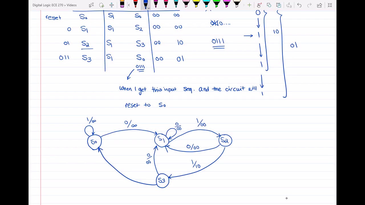
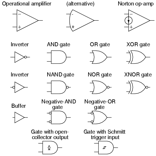
39 state diagram to circuit
State diagram - Wikipedia A state diagram is a type of diagram used in computer science and related fields to describe the behavior of systems. State diagrams require that the system described is composed of a finite number of states; sometimes, this is indeed the case, while at other times this is a reasonable abstraction.Many forms of state diagrams exist, which differ slightly and have different semantics State Machine Diagram for Pattern Recognition / Sequence Detector Sequence Detector is a digital system which can detect/recognize a specified pattern from a stream of input bits. Sequence Detector Conceptual Diagram. Let's say the Sequence Detector is designed to recognize a pattern "1101". Consider input "X" is a stream of binary bits. When the Sequence Detectors finds consecutive 4 bits of input ...
Sequential Circuits - tutorialspoint.com Circuit Diagram Truth Table Operation Delay Flip Flop / D Flip Flop Delay Flip Flop or D Flip Flop is the simple gated S-R latch with a NAND inverter connected between S and R inputs. It has only one input. The input data is appearing at the output after some time. Due to this data delay between i/p and o/p, it is called delay flip flop.
State diagram to circuit
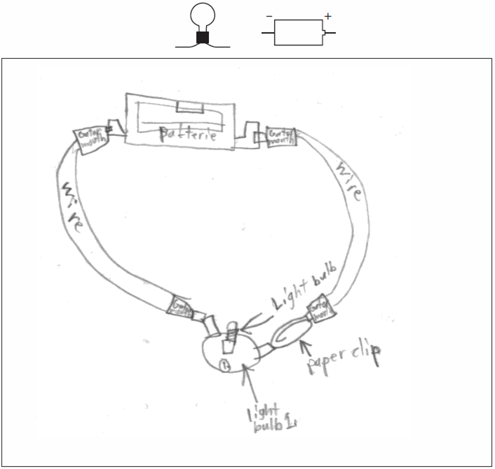
Finite State Machines | Sequential Circuits | Electronics Textbook The State Diagram of our circuit is the following: (Figure below) A State Diagram Every circle represents a "state", a well-defined condition that our machine can be found at. In the upper half of the circle we describe that condition. The description helps us remember what our circuit is supposed to do at that condition. Converting State Diagrams to Logic Circuits - ETSU This "enhanced" light bulb state diagram is shown below. The states are as follows: STATE 1 -- The reset state has the bulb turned off and waiting for the button to be pushed to turn it on. As long as the button remains released, the system will remain in this state. Once the button is pressed, the system is moved to state 2. Circuit Diagram - A Circuit Diagram Maker Circuit Diagram is a free application for making electronic circuit diagrams and exporting them as images. Design circuits online in your browser or using the desktop application.
State diagram to circuit. how to draw state diagram of sequential circuit? - EE-Vibes Fig. (a) state diagram Each circle has a binary number inside it that represents the condition it represents. Two binary numbers separated by a slash (/) are used to label the directed lines. The input value that triggers the state shift is the first to be labelled. The value of the output is the number after the slash symbol /. All You Need to Know about State Diagrams - Visual Paradigm A State Machine Diagrams shows the possible states of the object and the transitions that cause a change in state. Take a look at the State Machine Diagram below. It models the transitioning of states for an incident. Such a state diagram focuses on a set of attributes of a single abstraction (object, system). PDF State Diagrams - Milwaukee School of Engineering State Diagrams •Finite State Machine •HDL Design Process 1) Identify the states -collectively these make a state variable 2) Identify the Inputs and Outputs 3) Create a state transition diagram 4) Name each state (create an enumerated type) 5) Code the state diagram using the FSM construct 1) Next State Logic 2) Register Update 3) Output ... State Diagrams and State Tables - Surrey At the start of a design the total number of states required are determined. This is achieved by drawing a state diagram, which shows the internal states and the transitions between them. All states are stable (steady) and transitions from one state to another are caused by input (or clock) pulses.
State Diagram and state table with solved problem on state reduction State diagram The state diagram is the pictorial representation of the behavior of sequential circuits. It clearly shows the transition of states from the present state to the next state and output for a corresponding input. In this diagram, each present state is represented inside a circle. Objective: Create state diagram and build the circuit | Chegg.com Transcribed image text: Objective: Create state diagram and build the circuit for a finite state machine. Requirement: Consider following state diagram and one-hot state assignment Reset A/0 w = 0 w = 1 0 F/0 State Code Y8Y7Y6Y5Y4Y3Y2Y1Y0 Name A 000000001 G/0 B 000000010 C 000000100 Ꭰ 000001000 E 000010000 H/0 F 000100000 G 001000000 H 010000000 E/1 I/1 100000000 Figure 1: A state diagram ... A simple guide to drawing your first state diagram (with examples) How to draw a state diagram. Each diagram usually begins with a dark circle that represents the initial state and ends with a bordered circle that represents the final state. Rectangles with rounded corners denote a state, and each one includes a label with the name of the state. Transitions are marked with arrows that link one state to another ... State Diagrams and State Transition Tables! - All About Circuits 1 1 - State3 (S3) 1 0 - State4 (S4) Then for the State Transition Table: -I put the possible inputs horizontally -I put the 4 states (S1-4) vertically -The cells indicate the next state given a particular input -The forward-slashes indicate conditions which can't happen Sound alright?! Cheers Like Reply N n9352527 Joined Oct 14, 2005 1,198
State Diagram - an overview | ScienceDirect Topics A state diagram is a form of flow model, used to represent state changes (navigation among screens) in response to user input actions. This is an abstraction to show and understand the main workflow patterns and paths. See also Section 20.4.4.2. State diagram (in UX) Circuit Operation, State Table, Excitation Table, Karnaugh Maps ... Circuit Operation, State Table, Excitation Table, Karnaugh Maps, & Circuit Drawing Circuit Operation From the state diagram we see two states are reflexive. If the state of flip-flops AB are 11 with input x = 0, the sequential circuit with remain in state 11. PDF Derive the state table and state diagram for the sequential circuit. Therefore, in the state diagram, there must be four states and eight transitions. Following these transition arcs, that as long as Cnt = 1, the sequential circuit goes through the states in the following sequence: 0, 1, 2, 3, 0, 1, 2,.... Creating a Circuit from a state diagram - YouTube Extra Credit for FinalDr. Schubert, CSUSB, Digital Logic CSE 310
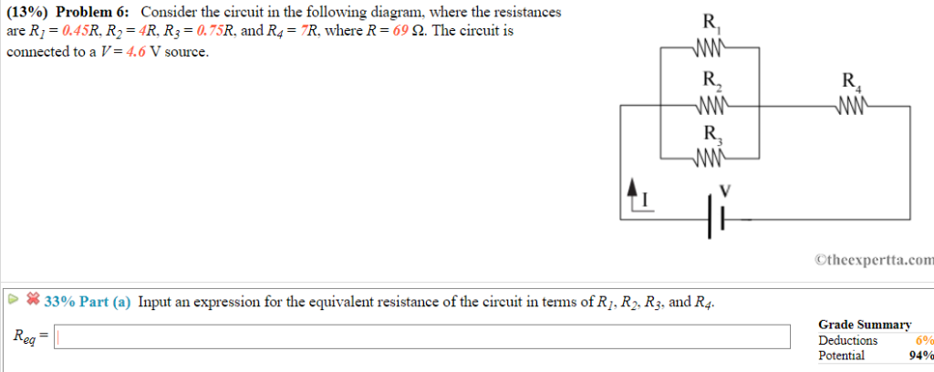
Consider The Circuit In The Diagram - Diagram For You
State Transition Diagram - an overview | ScienceDirect Topics The state transition diagram as shown in Figure 8.6 illustrates the active and quiescent states that are supported by the logic and the paths between these states. The state transition diagram also illustrates the states and transitions of the communication protocol between the recipe phase and the equipment phase.
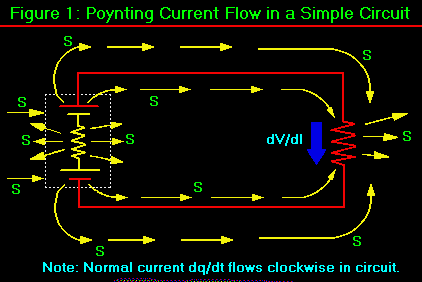
Progress Report on Poynting Current
Online State Machine Diagram Tool - Visual Paradigm Design State Machine Diagram online VP Online features a powerful UML diagram tool that lets you create state machine diagram and other UML diagrams easily and quickly. You can construct your diagrams with drag and drop, save your work in cloud workspace, output and share your design via numerous formats such as PNG, JPG, SVG, PDF, etc.
Circuit Diagrams And Component Layouts
State Diagrams - Everything to Know about State Charts Specifically a state diagram describes the behavior of a single object in response to a series of events in a system. Sometimes it's also known as a Harel state chart or a state machine diagram. This UML diagram models the dynamic flow of control from state to state of a particular object within a system.

10A Solid State Relay Technical Data
State Diagram - MATLAB & Simulink - MathWorks A state diagram or a state transition diagram is a graphical representation of a state machine's finite number of states, state transitions, and rules that govern the transitions. State diagrams are used as high-level starting points for complex software design because their simplicity allows clear communication of different modes of operation.

Understanding Circuit Diagrams - AP Physics 1
Q. 5.8: Derive the state table and the state diagram of the sequential ... Q. 5.8: Derive the state table and the state diagram of the sequential circuit shown in Fig. P5.8. Explain the function that the circuit performs.Please subs...
Mealy Sequential Circuit State Graph and State Table - YouTube
Ultimate State Diagram Tutorial: Explain with Examples With that being said, here are the steps that you can follow to create a UML state diagram. Launch GitMind from your browser. Click the "Get Started" button from the homepage, and the main-interface will appear. Next, click the "New Flowchart" button to switch to the editing panel. You can now start editing your diagram.
Lessons In Electric Circuits -- Volume V (Reference) - Chapter 9
State Diagram | How to Design State Diagram | Uses | Example A state diagram is used to design the dynamic aspect of the system. It defines the state of the components and state changes triggered by an event. Events are internal and external factors influencing the system. During system implementation, it is important to clarify the different states of the object during its lifetime.

PI Zero Solid State Tesla coil | Extreme Electronics
State Diagram Maker | State Machine Diagram Tool | Creately State Diagram is a Unified Modelling Language (UML) diagram type in computer science. It is used to describe how a system behaves when an event is observed by considering all the possible states, transitions, and actions of an object. How to Create a State Diagram?

RFID Based Automatic Toll Collection System Using Arduino Nano
UML State Diagram: A Useful Guide - Edraw - Edrawsoft TRY IT FREE. Security Verified | Switch to Mac >>. Step 2: Find and click on "Software" under the "Available Templates" option. In the middle column, a list of templates appears. Step 3: Click on "UML Model Diagram" then on the lower right is the create option. Click on it to open a blank window.

Pin on Electrical circuit diagram
PDF Sequential Circuit and State Machine State Transition Diagram (or State ... Sequential Circuit and State Machine 2 • Example: - A very simple machine to remember which building I am at - The only input is the clock signal - The state machine is represented as a state transition diagram (or called state diagram) below - One step (i.e., transition) can be taken whenever there is a clock signal
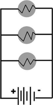
Figure 6.3
PDF Circuits with Flip-Flop = Sequential Circuit Circuit = State Diagram ... Circuit, State Diagram, State Table More ExampleMore Example: Word Problem: Word Problem Design a 2-bit complex counter with one input x that can be - a down counter when x=0 (...Æ11Æ10Æ01Æ00Æ11Æ...)-a Jh t h 1(Johnson counter when x=1 (...Æ00Æ01Æ11Æ10Æ00Æ...) 00 01 0 1 present state next state

How to find the current in the diagram - Electrical Engineering Stack ...
Circuit Diagram - A Circuit Diagram Maker Circuit Diagram is a free application for making electronic circuit diagrams and exporting them as images. Design circuits online in your browser or using the desktop application.
Lessons In Electric Circuits -- Volume VI (Experiments) - Chapter 8
Converting State Diagrams to Logic Circuits - ETSU This "enhanced" light bulb state diagram is shown below. The states are as follows: STATE 1 -- The reset state has the bulb turned off and waiting for the button to be pushed to turn it on. As long as the button remains released, the system will remain in this state. Once the button is pressed, the system is moved to state 2.
Types of circuits + your pics
Finite State Machines | Sequential Circuits | Electronics Textbook The State Diagram of our circuit is the following: (Figure below) A State Diagram Every circle represents a "state", a well-defined condition that our machine can be found at. In the upper half of the circle we describe that condition. The description helps us remember what our circuit is supposed to do at that condition.
Electrical Circuit Labeled - Circuit Diagram Images

Push on Push off Switch Circuit - Latching Circuit Diagram - YouTube
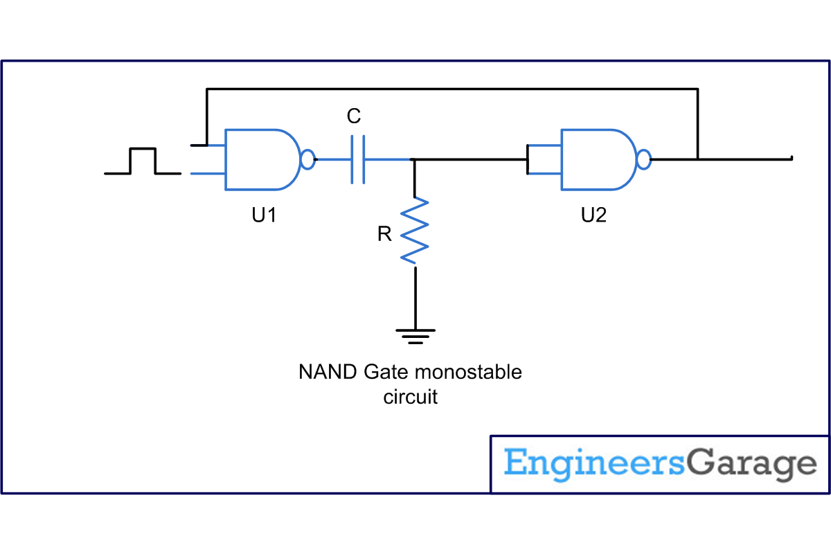
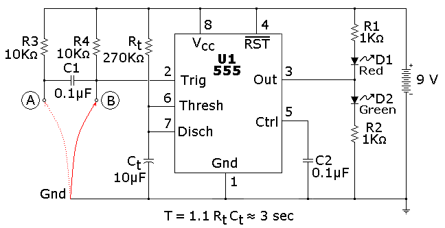
Monostable mode of 555 timer using NAND gate
0 Response to "39 state diagram to circuit"
Post a Comment