38 12 24 volt trolling motor wiring diagram
12V Trolling Motor: Thrust, Wiring & Top Picks (Batteries Included) According to our test, this 12v electric trolling motor provides satisfying trolling speeds and run time. A 50Ah battery can power the motor for 1hr at speed 5 continuously and roughly 3hrs at speed 3. #2. Best for Remote Control: AQUOS Haswing Trolling Motor How to Hook Up a Motorguide Trolling Motor 12/24 Volt System 12-Volt Wiring. Run the black wire from the trolling motor to the boat battery and loosen the negative terminal with a wrench. Slide the black wire over the terminal and tighten it down. Loosen the two terminals on the circuit breaker supplied with the trolling motor. Slide the red wire from the motor over one of the terminals and tighten it down.
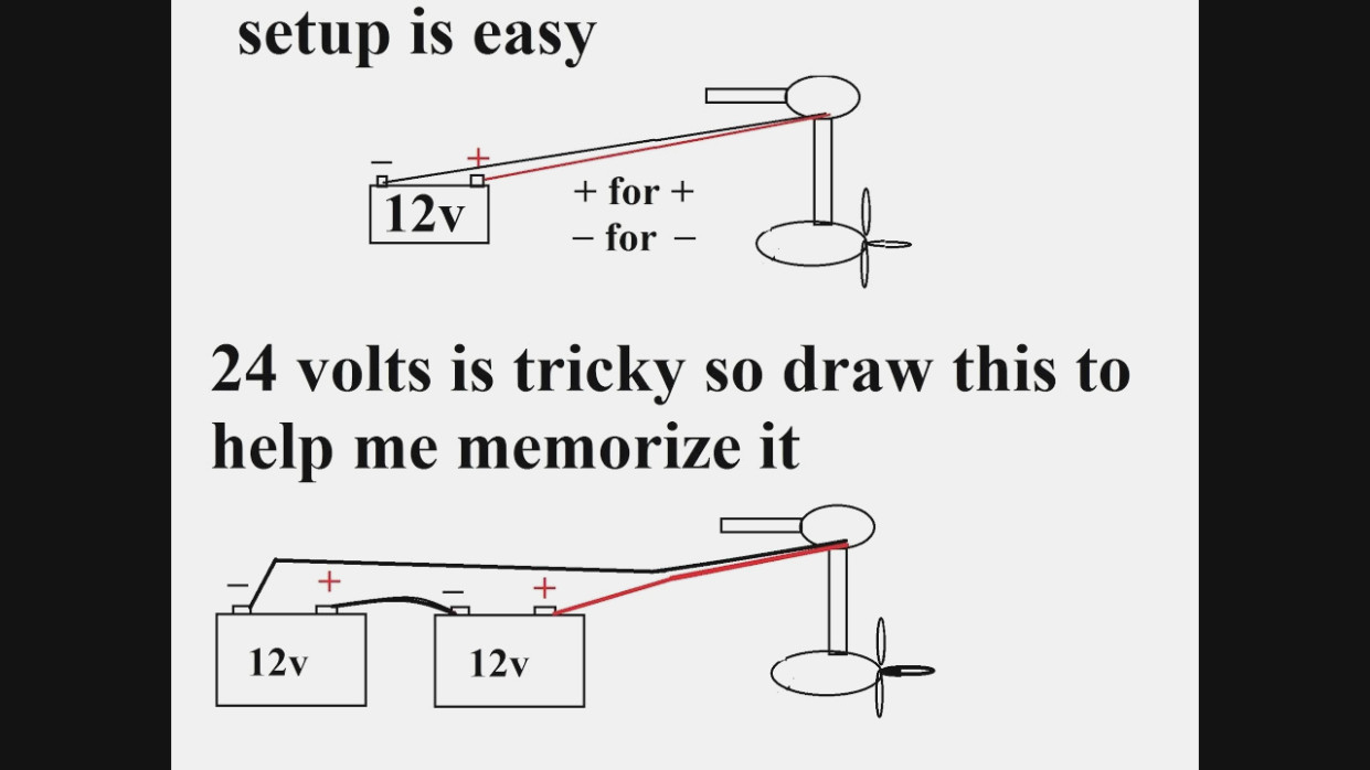
Trolling Motor Wiring and Battery Guide - Minn Kota Motors 24 Volt System (4 Batteries) Four 12-volt deep cycle batteries are required. Batteries in the system must be the same manufacture, type, size, and age. Make sure that the trolling motor is disconnected. Wire in parallel only as directed in wiring diagram, to provide 12-volt system with increased amp hour capacity.
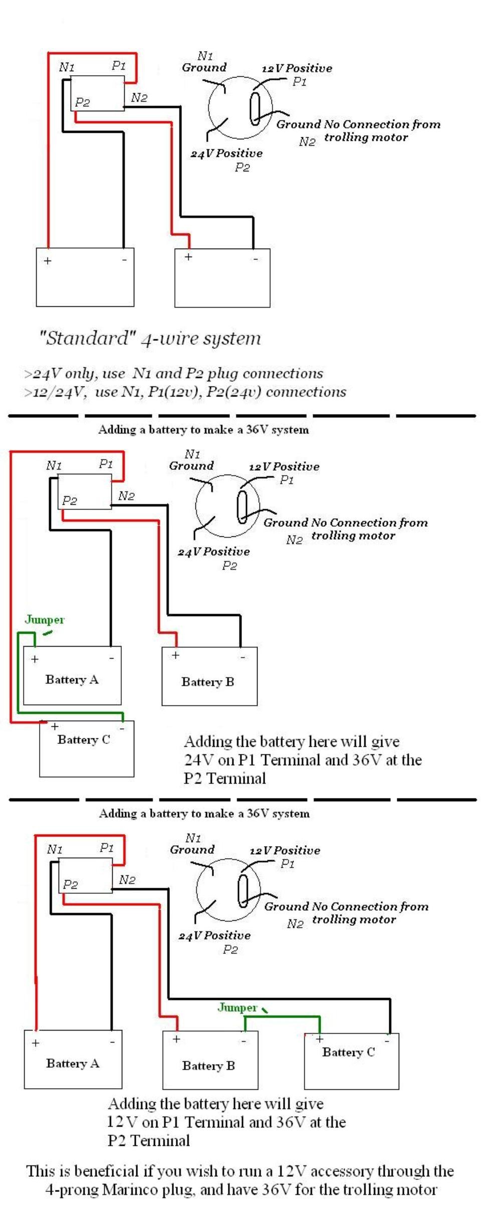
12 24 volt trolling motor wiring diagram
Health & Safety Meeting Dates - University of Cape Town Feb 08, 2022 · IDM HS committee meetings for 2022 will be held via Microsoft Teams on the following Tuesdays at 12h30-13h30: 8 February 2022; 31 May 2022; 2 August 2022 Emerson Motor Wiring Diagram Gallery - Wiring Diagram … Sep 26, 2019 · Name: emerson motor wiring diagram – Emerson Electric Motor Wiring Diagram Kanvamath Org Fan Perfect Psc Emerson Wiring Diagram Electric Motor; File Type: JPG; Source: imovo.co; Size: 162.26 KB; Dimension: 566 x 782 trollingmotorsguide.com › how-to-wire-a-24-voltHow to Wire a 24-volt Trolling Motor — Step-by-Step Guide Jun 24, 2020 · So let’s finally get to the answer to the question of how to Wire a 24-volt Trolling Motor? How to wire a 24-volt trolling motor using two 12v batteries Step 1: Prepare everything you need. Get the necessary tools and equipment to wire your 24v trolling system. In this case, you need: two 12v deep cycle batteries; a battery connector cable;
12 24 volt trolling motor wiring diagram. 12 24 Volt Trolling Motor Wiring Diagram - Collection There are wire extensions available if you finish up cutting them short, but the wiring will work better if it is intact. Since a rule of thumb, you'll want to have wiring that is very long to extend 3 inches outside of the electrical box. 4. Hide gaps in drywall with oversized plates faceitsalon.com › emerson-motor-wiring-diagramEmerson Motor Wiring Diagram Gallery Sep 26, 2019 · Name: emerson motor wiring diagram – Emerson Electric Motor Wiring Diagram Kanvamath Org Fan Perfect Psc Emerson Wiring Diagram Electric Motor; File Type: JPG; Source: imovo.co; Size: 162.26 KB; Dimension: 566 x 782 Chapter 116 Flashcards | Quizlet The wiring method will be 12 AWG wire with an EGC installed in EMT. Which of the following boxes is the smallest that can be used for the outlet box? ... The troll motor is rated for 24-volt DC operation. 24. Refer to Figure 116.310. ___ volts is being supplied to the trolling motor in Diagram II. 16. With the switch ON, the meter shown in ... PDF 12 24v Trolling Motor Wiring Diagram Johnson motor, evinrude trolling motor parts catalog motorcyclepict co, installing 24v battery system for trolling motor 24 volt battery, 12 24 volt switch trolling motor wiring diagram images, 12 24 volt trolling motor wiring help this old boat, evinrude trolling motor wiring diagram vivresaville com, how do you wire a boat up for a 24volt minn kota ...
Tracker Boats Wiring Diagram | TackleReviewer Mar 30, 2010 · Wiring color diagram for Tracker and Bass Tracker boats. Use this as a reference when working on your boat wiring. ... I have the 12 volt starting battery all hooked up…how ever I have not hooked up the 24 volt system for the trolling motor as I’m sure these fish finders do not run off those battery’s and help or leads would be ... › freebies › tracker-boatsTracker Boats Wiring Diagram | TackleReviewer Mar 30, 2010 · I have 92 tracker pro 17 evinrude 50 just got it I need the wiring diagram for the lights, pumps and evering, plus how many pumps and plumbing as well PLEASE bear with me, im a 20 yr vet from 72-92 leagally blind and have tunnel vision meaning looking thru a straw at 10 feet can you help thanks ray newboatbuilders.com › pages › electricity13Boat Building Standards | Basic Electricity | Wiring Your Boat Note 2: If you are re-wiring a boat with an electrical system installed: Don't rip out that old system yet! Use the old system to help make a plan in steps 1 through 7. Trace out each wire and put that on your diagram. This will make it far easier to locate wires and equipment. Wait until you actually start installing wiring in step 12. 12/24 Volt Trolling Motor Wiring Diagram Wiring a trolling motor to the boat's battery is a simple process, once you know where to connect the wires. A 24v system requires two 12v batteries that are. wiring diagram Volt Motors 1. Connect the RED lead from the trolling motor power cable to the positive (+) battery terminal. Use a amp circuit breaker on.
Marine Propulsion Controls - Glendinning Products Wiring Diagram; Buy parts online ; ... Motor Yachts, Sport Fishers, Trawlers, Work Boats, and Military Vessels. All Electronic & Mechanical Engines & Transmissions Including. ... 12 & 24 volt; Optional Features. Handheld remote control; Trolling valve control; Integrated back up system; 12/24 volt switch trolling motor wiring diagram - iboats.com The purpose of the 12/24 switch is to put the batteries in parallel so they can be charged by a single charger. If you have a multiple bank charger, it is not needed. 1. Discard the switch. 2. Connect the negative terminal of battery #1 to negative on the trolling motor. 3. HELIX® SERIES Installation Guide - Johnson Outdoors 12 to 24 ft 12 AWG Please consult a U.S. Coast Guard ABYC-approved wire gauge ... Some boats have 24 or 36 Volt electric systems, but the control head MUST be connected to a 12 VDC power supply. ... NOTE: If you have a trolling motor, it is important to keep the control head power and trolling motor power as separate as possible. 4 ... 12 24 trolling motor wiring HD 50 Amp 12 & 24 Volt Boat Trolling Motor Circuit Breaker Kit W . breaker circuit trolling motor amp volt inline boat kit. Trolling wiring motor volt diagram 24v wire 12v plug batteries minnkota system battery series regarding box fuse voltage. Simple wiring diagram for boat single battery / 12 24 trolling motor. Hd 50 amp 12 & 24 ...
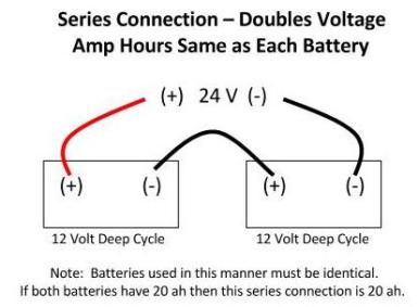
24 Volt Trolling Motor Wiring Schematic The 24V trolling motor wiring schematic often shows two 12V batteries connected in a series. Connecting two 12V batteries in series provides the 24V power source required to run your motor. The wiring is not complex, and you can wire your motor using the schematics below without a professional.
24v Motor Trolling Search: 24v Trolling Motor. Trolling Motor Accessories Mounting kits, replacement propellers and other trolling motor accessories simplify the use and maintenance of a trolling motor so you can focus on the actual trolling This 4-wire, electrical female Trolling Motor Receptacle from Bass Pro Shops is made for 12V to 24V trolling motors read more Designed to fit all hand-operated 12V or 12/24V ...
How to Wire an Evinrude Scout 12-24 Trolling Motor - Gone Outdoors Remove the nut from the positive post of the first battery in your battery box, using a 3/8-in. open-end wrench. Set the ring terminal of the red motor wire around the post. Return the nut to the post, tightening it securely. Remove the nut from the negative post of the same battery, using a 5/16-in. open-end wrench.
12/24 volt trolling motor wiring HELP!!! - Lake Ontario United 12/24 volt trolling motor wiring HELP!!! By idn713, December 14, 2011 in This Old Boat. Share More sharing options... Followers 0. Recommended Posts. idn713. Posted December 14, 2011. idn713. 158 837 Share; Posted December 14, 2011.
MINN KOTA ULTERRA OWNER'S MANUAL Pdf Download | ManualsLib WITH i-PILOT BOW-MOUNT TROLLING MOTOR. ULTERRA outboard motor pdf manual download. Sign In. Upload. ... Motor Wiring Diagram. 15. Getting Started. 15. Knowing Your Remote. 17. Knowing Your I-Pilot Controller. 17. ... Page 44 …
quizlet.com › 462998634 › chapter-116-flash-cardsChapter 116 Flashcards | Quizlet Which connection diagram in Figure 116.310 shows all the equipment correctly connected? The downrigger and the pump are both rated for 12-volt DC operation. The troll motor is rated for 24-volt DC operation.
show wiring diagram for a 12-24 v evinrude scout trolling motor DOWNLOAD show wiring diagram for a 12-24 v evinrude scout trolling motor - Back to all "Outboard Motors" - Johnson parts catalog Original OMC Factory Service Manual provides detailed information on repair, maintenance and troubleshooting for Johnson/Evinrude Electric outboard motors.
Trolling Motor Wiring Diagrams | Minn Kota Motors The following schematic outlines the necessary accessories/cables needed to connect a trolling motor to a 24 volt system. COMPATIBLE ACCESSORIES Trolling Motor Trolling Motor Plug *Optional - MKR-26 (1865128) 12 Volt Battery (2 Batteries Required) Circuit Breaker - MKR-19 (1865106) Red Line = 12V DV Power
› manual › 1045016MINN KOTA ULTERRA OWNER'S MANUAL Pdf Download | ManualsLib WITH i-PILOT BOW-MOUNT TROLLING MOTOR. ULTERRA outboard motor pdf manual download. ... Page 12: Battery & Wiring Installation ... Page 44 s dIAgRAm 24 Volt Motor 36 ...
24 and 36-volt Wiring Diagrams - TrollingMotors.net Both the 24v and 36v trolling motor wiring diagrams are listed below along with the recommended circuit breaker. It is important to note you should never feed more voltage into a motor than what it is rated for (ie. never feed 24 volts into a 12v motor!). 24 Volt Wiring Diagram 36 Volt Wiring Diagram Connecting Your Battery Charger
PDF Trolling Motor Battery Wiring Installation Diagrams 12 volt system. The accessories and part numbers listed above are valid as of April 2020. 3Neg -Pos + 24 volt system. FOR MORE INFORMATION ON WIRING BATTERIES, PLEASE REVIEW CONDUCTOR GAUGE CHART. Neg - 3 36 volt system. 3) Neg - 3Neg -Pos + 48 volt system. 4)
› Health_Safety_Meeting_DatesHealth & Safety Meeting Dates | Institute Of Infectious ... Feb 08, 2022 · IDM HS committee meetings for 2022 will be held via Microsoft Teams on the following Tuesdays at 12h30-13h30: 8 February 2022; 31 May 2022; 2 August 2022
PDF INSTALLATION/WIRING INSTRUCTIONS - Marinco 3. Insert the negative wire into terminal 1 and the positive wire into terminal 2. For three-wire motors (either 12/24 or 24/36V) insert the highest voltage wire into terminal 3. Make certain there is no wire insulation inside the terminals, and there are no stray wire strands outside the terminals. Tighten the terminal screws to 12 in-lbs ...
Motorguide 12 24 Volt Trolling Motor Wiring Diagram MOTORGUIDE WIRING DIAGRAMS. When connecting each jacketed 24 VDC Trolling Motor Battery Configuration with (2) 12 VDC Batteries . wiring diagram Volt Motors Use two volt deep-cycle marine batteries and connect as follows: 1. Connect the BLACK wire from the trolling motor power. 54 V DS. 82 V DS. V DS. !!!!
SUZUKI DF300 SERVICE MANUAL Pdf Download | ManualsLib Turn main switch ON and measure terminal voltage. Circuit Terminal Output voltage Shift motor relay Approx. 0.5 V Motor power source 69 or 77 Approx. 12 V Shift motor + Approx. 0 or 12 V Shift motor - Approx. Page 140 ENGINE CONTROL SYSTEM 3-81 ELECTRONIC THROTTLE BODY Throttle valve visual check 1. Remove the ring gear cover and air intake ...
12 Volt Trolling Motor Wiring Diagram - Database It's always better to have too much wire than not enough. There are wire extensions available if you finish up cutting them short, but the wiring will work better if it is intact. Since a rule of thumb, you'll want to have wiring that is very long to extend 3 inches outside of the electrical box. 4. Hide gaps in drywall with oversized plates
Boat Building Standards | Basic Electricity | Wiring Your Boat Note 2: If you are re-wiring a boat with an electrical system installed: Don't rip out that old system yet! Use the old system to help make a plan in steps 1 through 7. Trace out each wire and put that on your diagram. This will make it far easier to locate wires and equipment. Wait until you actually start installing wiring in step 12.


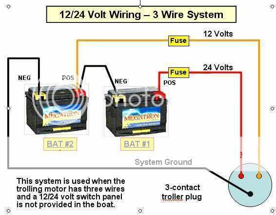
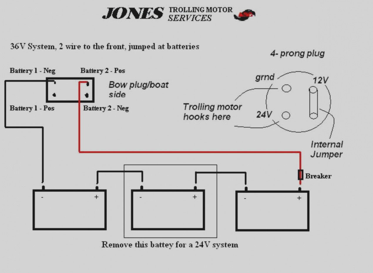


0 Response to "38 12 24 volt trolling motor wiring diagram"
Post a Comment