45 lighting contactor wiring diagram with photocell
Lighting Wiring Diagram With Contactor - LayneHouse Class 8903 Type Lx Mechanically Held Lighting Contactor 2 Thru 12 Pole Forms G10 3 Wire Power Photocell R6 Two Control Relay C Hoa Selector Switch Latch Coil Ch1 14 On. Panel and DIN rail mounting Full line of enclosures including NEMA 1 33R 4 44X. ... Square d 8903 lighting contactor wiring diagram Lighting Contactor Wiring Diagram With cell ... How to wiring Photocell with magnetic Contactor connection Part 3 Electrical Vlog
Lighting Contactor With Photocell Wiring Diagram Then feed from live to photocell. switchwire back to top of contactor. Then on the bottom have lighting contactor wiring diagram with photocell.Oct 07, · Unswitched control power should be on the NO relay contact, also going to contactor coil. Last the photocell output should be connected to the relay's coil.
Lighting contactor wiring diagram with photocell
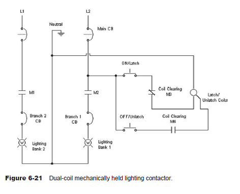
Lighting Wiring Diagram With Contactor Volume 10 Tab 4. Square D Lighting Magnetic Contactor 120v Ac Coil Volts Type Electrically Held Number Of Poles 2cg65 8903lo40v02 Grainger. Contactorotor Starters. Contactor Overload Maintained Switch Wiring For Magnetic Motor. Selecting Effective Lighting Control White Paper. Square D 8903 Lighting Contactor Wiring Diagram Inspection/Repair Steps (Reference diagrams below). Step 1 Confirm that the normal mounting of the lighting contactor is upright and vertical on vertical plane ( panel). The coil clearing contact which is wired to the SQ (A 2/3P) Latch Coil (ohms) SV (A 2 thru 5P) Latch Coil (ohms) SQ/SV (2 thru 5P) Unlatch. Contactor And Photocell Wiring Diagram Then feed from live to photocell. switchwire back to top of contactor. to your sensor with a neutral looped to contactor terminal A2 and your sensor switch wire to terminal A1. lighting contactor wiring diagram with photocell. The proper voltage rated photocell must be used or damage will occur.
Lighting contactor wiring diagram with photocell. Timer And Contactor Wiring Diagram - Wiring Schematic Online Timer and contactor wiring diagram. This energized star contactor coil and motor get connected in star. A simple circuit diagram either of the two start buttons will close the contactor either of the stop buttons will open the contactor. Star delta starter open type ra ted ac3 at 400v 205a rated control voltage 230v 50hz order type. › Full_MembersFull Members | Institute Of Infectious Disease and Molecular ... Full membership to the IDM is for researchers who are fully committed to conducting their research in the IDM, preferably accommodated in the IDM complex, for 5-year terms, which are renewable. Contactor And Photocell Wiring Diagram - schematron.org Then feed from live to photocell. switchwire back to top of contactor. to your sensor with a neutral looped to contactor terminal A2 and your sensor switch wire to terminal A1. lighting contactor wiring diagram with photocell.These are the wiring diagrams for lighting and heating contactors. thienmaonline.vn › 1650748780-2- Thienmaonline diff –git a/.gitattributes b/.gitattributes index 74ff35caa337326da11140ff032496408d14b55e..6da329702838fa955455abb287d0336eca8d4a8d 100644 — a/.gitattributes
480V photocell wiring diagram - Electrician Talk The photocells still only break one leg to the light. I would need to use a contactor to achieve that. ... I have a question: I am looking for a remote photo cell wiring diagram for a 480V single phase fixture. The application is a single 400W HPS 480V (single phs) pole mounted light fixture on a wooden power pole. ... How to Install and Wire a Photocell Switch in a Lighting Installation In lighting applications, Photocells are placed in streetlights to control when the lights are ON or OFF. During daylight, light falling on the photocell causes the streetlights to turn off and during night hours or darkness to turn on. Thus energy is saved by ensuring the lights are only on during hours of darkness. 240v Photocell Wiring Diagram Volt photocell wiring. Refer to the wiring diagrams below and choose the appropriate diagram. b. For V, V, V or V Units: Connect the White wire from the light. Wiring a Dusk to Dawn Photocell Sensor: I bought a photocell sensor on eBay after learning Lowes, Here is my wiring diagram (third photo) and instructions. Lighting control wiring diagram / detail ? | Mike Holt's Forum Dec 16, 2008. #3. no diagram, but we used to do a pretty simple wiring set up. Feed the photocell and clock motor with "Line" (and neutral) (this often entails taking the motor lead off the contcat terminal) Run the "load" of the photocell thru the clock contacts. and feed the contcator/light. In this manner, the clock motor runs all the time.
Photocells & Timers - Electrical 101 Photocell and Timer Wiring Diagram 1 Photocell and Timer Wiring Photocell and timer switch wires each have a line (black), load (red), neutral (white), and ground (green). The black line wire connects to line voltage from the panel, the red load wire connects to the light (s), the white neutral wire connects to the neutral wires of the circuit. Lighting Contactor Wiring Diagram with Photocell | Electrical ... mesothelioma - structured settlement - vioxx attorney - drug rehab - contract management software - car accident lawyer - note buyers - donate a car - investment fraud - PDF Lighting contactors (open) - Eaton 6.1Lighting Contactors Open Control Features See figure below. 30A power pole rating Up to 12 poles maximum Power poles latch easily onto the base, and designating them as NO or NC is a simple matter of left or right positioning. Additional poles, either NO or NC, may be easily added at any time Low magnetic noise results in quiet operation Lighting Contactor Wiring Diagram With Photocell Database Lighting Contactor Wiring Diagram With Photocell from wholefoodsonabudget.com Print the wiring diagram off in addition to use highlighters to be able to trace the routine. When you employ your finger or perhaps follow the circuit with your eyes, it is easy to mistrace the circuit. One trick that I 2 to printing the same wiring diagram off twice.
› document › 179242518Brit A Z | PDF | Nature - Scribd aardvark aardvarks aardvark's aardwolf ab abaca aback abacus abacuses abaft abalone abalones abalone's abandon abandoned abandonee. abandoner abandoning abandonment abandons abase abased abasement abasements abases abash abashed abashes abashing abashment abasing abate abated abatement abatements abates abating abattoir abbacy abbatial abbess abbey abbeys abbey's abbot abbots abbot's ...
How to wire a photocell to multiple lights. | Theop Power Solutions lighting contactor wiring diagram with photocell. photocell wiring diagram with contactor You run electrical cable from the the circuit breaker in consumer unit.to the contactor.I must mention that you run the cables arcording to the number of lighting circuit.For example,if you have 3 circuits,you run 3 cables from the DB to the contactor.
How To Wire A Photocell To Multiple Lights - Yard and Garden Guru The steps for wiring a photocell switch sensor are outlined below. The first step is to turn off all electrical power to the light fixture where you wish to install the photocell. Using a screwdriver, remove the light from the electrical box. Remove the two wire nuts that connect the wires to the light fixture and power supply.
Lighting Contactor Wiring Diagram With Timer Time Switch For Home Lighting Light Timer Manufacturer. Single Phase Motor Starter With Timer Diagram Earth Bondhon. Lighting Circuits Connections For Interior Electrical Installations 2. Wiring A Contactor With An Mcb And Rccd D I Y Kit Uk420. Programmable Timer Relay 8 Input Output 12v 24v Dc Ato Com. 0137 Emergency Exit Light Test Controller V2.
HOW TO WIRE A PHOTOCELL IN A CIRCUIT - YouTube VIDEO: HOW DOES A PHOTOCELL WORK? - PHOTOCELL: US STORE UK STORE ...
How to Wire a Photocell Switch to Lighting Loads with a Contactor The schematic wiring diagram below shows how to wire a photocell switch with a 3-phase contactor to power nine (9), 250W lighting loads: Note that on the photocell sensor, L1 is the live wire, N is the neutral wire and Lo, is the load wire which goes to energize the contactor coil which must be rated for the phase voltage ( L1-N or L2-N or L3 ...
Understanding a contactor for lights run by a photocell. Your contactor is probably 2, 3 or 4 pole, run your Live and Neutral through the L1 and L2 (first 2 poles) then to your lights, then from a seperate mcb run a control circuit to your sensor with a neutral looped to contactor terminal A2 and your sensor switch wire to terminal A1.
› Members_Meeting_DatesIDM Members Meeting Dates 2022 | Institute Of Infectious ... Feb 16, 2022 · IDM Members' meetings for 2022 will be held from 12h45 to 14h30.A zoom link or venue to be sent out before the time.. Wednesday 16 February; Wednesday 11 May; Wednesday 10 August
Photocell Wiring Diagram With Contactor - Diagram : Template Sample ... Posts Related to Photocell Wiring Diagram With Contactor. Photocell Wiring Diagram Uk. 240v Photocell Wiring Diagram. 480v Photocell Wiring Diagram. ... Mechanically Held Lighting Contactor Wiring Diagram. Schneider Electric Contactor Lc1d09 Wiring Diagram. Pin It Tweet. About the Author Jose Silva. Recent Posts.
Lighting Contactor Wiring Diagram With Photocell Wiring Diagrams. controls such as photocells and timers. Terminal blocks included for Table Enclosed Lighting Contactor Catalog Numbering System. I have 3 lighting feeds and one 3 core to the photocell, the time clock is to be . Here is the schematic for your application, minus the power.
PDF Lighting Contactor Wiring Diagram With Photocell Lighting Contactor Wiring Diagram With Photocell Author: tourismtreasures.tourismthailand.org-2022-06-02-19-40-41 Subject: Lighting Contactor Wiring Diagram With Photocell Keywords: lighting,contactor,wiring,diagram,with,photocell Created Date: 6/2/2022 7:40:41 PM
Lighting Contactor Wiring Diagram With Photocell Tabelec Sarl Motor Contactor Wiring Diagram Electrical Class 8903 Type Lx Mechanically Held Lighting Contactor 2 Thru 12 Pole Forms G10 3 Wire Power Photocell R6 Two Control Relay C Hoa Selector Switch Latch Coil Ch1 14 On Lighting Contactors Time Clock And Photo Cell Electrician Talk How Does A Photocell Works With Contactor Quora
› document › 240903411Cessna 172 Maintenance Manual | PDF | Airplane | Landing Gear Jul 23, 2016 · This manual has been prepared in accordance with the Air Transport Association (ATA) Specification Number 100 for Manufacturer's Technical Data. C. Information beyond the scope of this manual may be found in the applicable Model 172 Wiring Diagram Manual, Model 172 Illustrated Parts Catalog and the Single Engine Models 172, 182, T182, 206 and ...
Contactor And Photocell Wiring Diagram Then feed from live to photocell. switchwire back to top of contactor. to your sensor with a neutral looped to contactor terminal A2 and your sensor switch wire to terminal A1. lighting contactor wiring diagram with photocell. The proper voltage rated photocell must be used or damage will occur.


0 Response to "45 lighting contactor wiring diagram with photocell"
Post a Comment