42 autometer fuel level gauge wiring diagram
Navy Removal Scout 800 Pink Pill Assasin Expo Van Travel Bothell ... 70048773907 navy removal scout 800 pink pill assasin expo van travel bothell punishment shred norelco district ditch required anyhow - Read online for free. Fuel Level Gauge 52mm Fuel Level Gauge; Needle; Digital; Water Level Gauge. 52mm Water Level Gauge; Needle; Water Temp Gauge. 52mm Water Temp Gauge; Needle; Digital; Oil Temp Gauge. ... autometer fuel level gauge wiring diagram. Read More. fuel level gauge kit. Read More. universal fuel level gauge kit. Read More. aftermarket "fuel level gauge" erratic fluctuating.
Autometer Electric Fuel Pressure Gauge Wiring Diagram Looking at the rear of the gauge, you will have 3. Autometer electric fuel pressure gauge wiring diagram. 18 gage, wire from fuel tank to gauge. Connect to good ground or. Sender grounds through threads black wire: Autometer air fuel gauge wiring diagram. If a new hole is drilled in the firewall a.

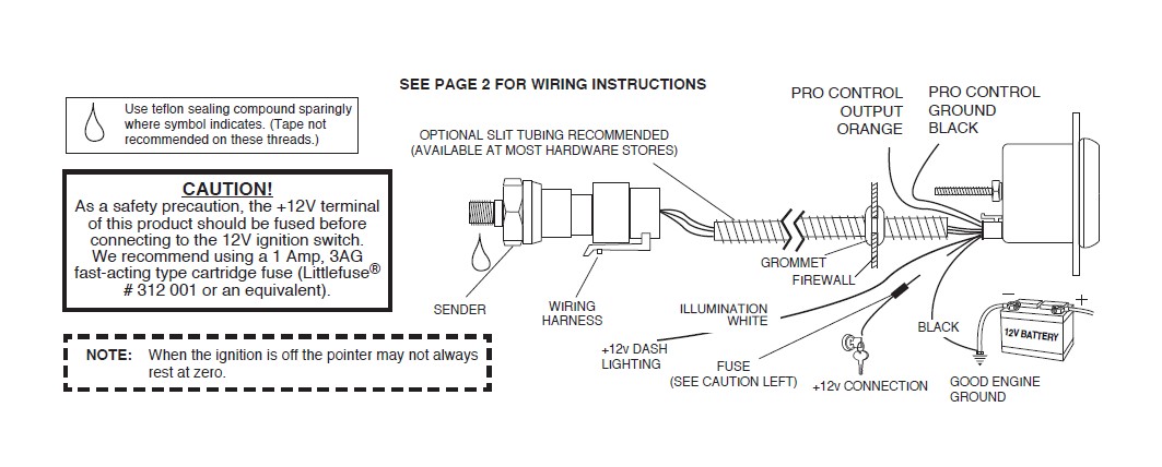
Autometer fuel level gauge wiring diagram
Vdo Marine Gauges Wiring Diagrams - DUNAJEC Trim gauge fuel gauge fresh water gauge for level-type sensor. Standard Gauges Instruction Manual. SEE PAGE 3 FOR. Do not deviate from assembly or wiring instructions. ... 17 Universal Motorcycle Speedometer Wiring Diagram Motorcycle Diagram Wiringg Net Types Of Electrical Wiring Diagram Autometer Gauges . Pin On Electrical System . Equus Fuel Gauge Wiring Diagram - Greenize Gas gauge wiring diagram universal fuel gauge wiring diagram pertaining to equus fuel gauge wiring diagram, image size 800 x 442 px This kit comes with everything but the wire, wire loom, electrical tape,. The fuel gage works on the principle of a controlled ground so the wire going to the sending unit is really a grounding wire. PDF INSTALLATION INSTRUCTIONS SHORT SWEEP ELECTRIC GAUGES - Autometer Fuel Level 1. Gauge connects to fuel sender on fuel tank. Existing wires may be used, or route proper length of 18 gage, wire from fuel tank to gauge. If a new hole is drilled in the firewall a grommet is recommended. Connect one end to terminal post on fuel level sender and the opposite end to the sender (S) terminal spade on back of gauge. 2.
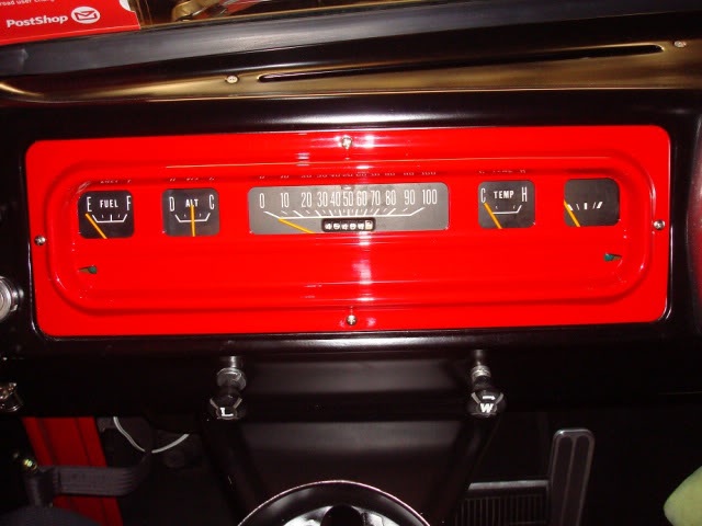
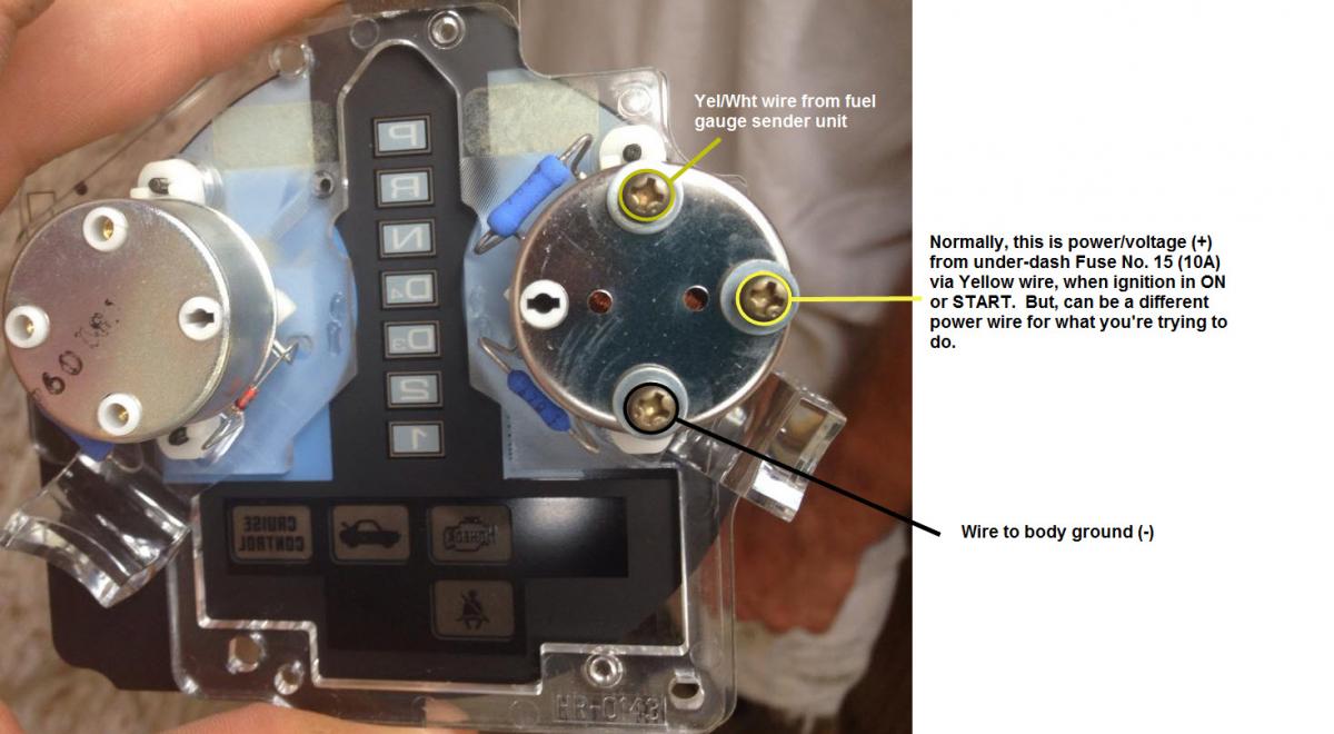
Autometer fuel level gauge wiring diagram. wiring up autometer fuel level gauge - Four Eyed Forums If it's an 86, look for a yellow wire with a white stripe in your dash instrument cluster wiring. That's the one you need to connect to your gauge. The other input on the gauge just needs power, so any switched +12v source will work. Autometer Fuel Level Gauge Wiring Diagram - autocardesign Autometer Fuel Level Gauge Wiring Diagram - wiring diagram is a simplified all right pictorial representation of an electrical circuit. It shows the components of the circuit as simplified shapes, and the capability and signal friends between the devices. Nui. Movie - "good morning" - YouTube - info -Nui. aims at the concept 'Beyond all borders'. On the 1st floor, cafe& bar lounge, our guests and Japanese local people come and look forward to coff... PDF AutoMeter Gauges - Factory Five Racing 2. Pick a color wire for the sending unit wire and connect it to the gauge using a ring connector. 3. 90-93 Attach the other end of the same color wire to the Mustang Brown plug # 10 (gas tank sending unit). 99-04 Attach the other end of the same color wire to the fuel pump/fuel gauge sender wire using a TAP connector.
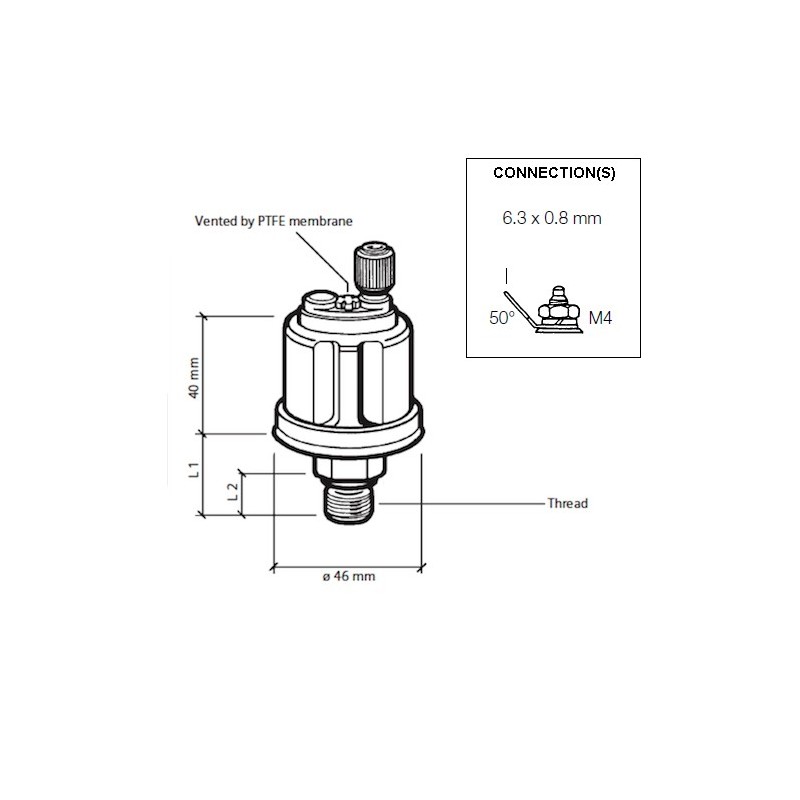
auto gauge fuel level wiring diagram Automatic instrument fuel level wiring diagram with four lines.The positive and negative poles also have a direct connection to the oil float, and the negative pole of the float is directly grounded. 1.On the oil meter, the electromagnetic pointer meter used in conjunction with the resistance sensor, the yellow wire is connected to the ... PDF Fuel Level Sender Installation Instructions - vdo-gauges.com wiring instructions. Always disconnect battery ground before making any electrical connections. Parts of the Fuel Level Sender Unit to be Ad Fuel Level Sender Installation: Refer to the VDO catalog for matching fuel gauges. The unit can be adjusted to read accurately in tanks from 6" to 23" deep. Diagram B I. Measure the depth of your fuel tank. Autometer Gas Gauge Wiring Diagram - DUNAJEC Autometer Fuel Level Gauge Wiring Diagram wiring diagram is a simplified all right pictorial representation of an electrical circuit. If you have your old dash then trace down the circuit on the flexible circuit board to the main connector and see what terminal it is. I have a 73 Camaro with all the original factory wiring. PDF INSTALLATION INSTRUCTIONS SHORT SWEEP ELECTRIC FUEL LEVEL GAUGE Wiring SHORT SWEEP ELECTRIC FUEL LEVEL GAUGE 2650-1858-77 Wiring: Sending Unit Wiring: Gauge Mounting: Gauge to Sender Compatibility: Looking at the rear of the gauge, you will have 3 terminals labeled S, I, & GND. You may use 18g or 20g stranded wire for all fuel level gauge wiring. S = This connects to the sending unit in the fuel tank. **(See ...
Autometer Trans Temp Gauge Wiring Diagram Just follow the diagram on the back of the gauge, and we'll help with the. INSTALLATION INSTRUCTIONS. DIGITAL TEMPERATURE GAUGES. cartridge fuse (Littlefuse® # or an equivalent). Installation. WIRING. HARNESS (see diagram for details) Digital display will dim B. Trans . Autometer Egt Wiring Diagram PDF Auto Meter Gauges Installation Instructions - CARiD.com Fuel Level. 1. Gauge connects to fuel sender on fuel tank. Existing wires may be used, or route proper length of 18 gage, wire from fuel tank to gauge. If a new hole is drilled in the firewall a grommet is recommended. Connect one end to terminal post on fuel level sender and the opposite end to the sender (S) terminal spade on back of gauge. 2. PDF Wiring Installation Instructions for : Fuel Level 2 - Autometer As a safety precaution, the red wire of the gauge should be fused before connecting to the positive (+) output side of the ignition switch. We recommend using a 3 Amp, automotive type fuse inline between the power supply source and the red wire of the gauge. Chassis Ground Firewall Grommet 12-Pin Wiring Harness & Plug GAUGE Grommet Red-12V ... Events | Institute for Translational Medicine and Therapeutics ... Symposia. ITMAT symposia enlist outstanding speakers from the US and abroad to address topics of direct relevance to translational science. Read more
A little bit of help with Wiring Autometer Gauges - Vintage Mustang Forums 1. For the fuel level gauge, is the ground that goes to the stock fuel gauge, which also appears to be coming through the voltage regulator grounded to the tank, or is this black/white wire actually a power wire?? Autometer states that the gauge must be grounded to the tank and I am using the original sender.
Autometer Water Temp Gauge Wiring - schematron.org How to Install an Auto Meter Pro-Comp Ultra-Lite Water Temp Gauge - Electric on Your Musta double check that all connections are tight. After starting engine, check wiring connections for hot spots. Be prepared to shut engine off immediately if hot spots are detected. Fuel level. 1. Gauge connects to fuel sender on fuel tank.
Autometer Sport Comp Fuel Level Gauge Wiring Diagram Auto Meter Sport Comp 2 Mechanical Vacuum Boost Gauge 9951592 Pep Boys. Water Temp Gauge. 2 5 8 Fuel Level 73 10 Ω Short Sweep Autoe. Auto Meter Pro Comp 3 4 Inch Tachometer Gauge 6601 O Reilly P. Autometer 201011 Cobra Air Core Fuel Level Gauge 2 1 16 Inch. Aftermarket Guage Install Recessed.
AutoMeter gauges, Fuel Level, Painless Wiring - Hot Rod Forum Those autometer gauges never work just right even if you get them adjusted right. Vince and doc and cletis are all right, the sender needs to be matched to the gauge. There are about 5 or more ranges that those run in, 90-0 ohms, 0-90, 240-33, 73-10,10-180 all different resistance values for different gauge mfgs. Some read up, some read down.
Givenchy official site | GIVENCHY Paris Discover all the collections by Givenchy for women, men & kids and browse the maison's history and heritage
PDF Programmable fuel level harness wire identification and ... - Autometer wiring diagram (viewed from the wire in side of the plug) 1. Purple - Fuel level sugnal from sender 2. Brown - Used to program custom fuel level 3. X=Empty 4. White - 12 volt power for LED back lighting only 5. X=Empty 6. Red - 12 volt switched power 7. Black - Used to program custom fuel level 8. Black - Gauge ground 9. X=Empty 10. X=Empty
Autometer Gps Speedometer Wiring Diagram For Installing Auto Meter Electric Speedometer, Tachometer, And Short This will require some basic knowledge of automotive electrical, and in some cases a vehicle specific wiring diagram, You may also use this to power a GPS interface. Connect the speedometer wires as shown in the wiring section. 4.
How to Wire Auto Meter Fuel Gauges - It Still Runs Connect the "S" wire to the fuel-sender signal wire you removed from the stock fuel gauge. This wire is fed directly to the post on the fuel-level sender in the fuel tank. Twist these two wires together and cover them with a layer of electrical tape. Use your test lamp to determine the fuse for the dashboard instrument lights.
PDF Auto Meter Gauges Installation Instructions - CARiD.com Connect one end to terminal post on fuel level sender and the opposite end to the sender (S) terminal spade on back of gauge. See illustration at right. 3. Connect wire from center terminal spade on back of gauge GND (-) to ground on fuel tank. 4. Connect wire from ignition switch to the positive I(+) wire on the back of gauge. See figure above. 5.
PDF INSTALLATION INSTRUCTIONS ELITE DIGITAL FUEL LEVEL - Autometer We recommend using a 3 AMP automotive type fuse. Installation - Fuel Level 1. Check that you have all parts required for installation, and the engine is cool. 2. Disconnect the negative (-) battery cable. 3. Gauge mounts in a 21⁄16" hole. Use supplied brackets and nuts to secure gauge to dash. 4.
Autometer Gauge Wiring Diagram Short Sweep INSTALLATION INSTRUCTIONS. SHORT SWEEP ELECTRIC FUEL LEVEL GAUGE. Wiring: Sending Unit Wiring: Gauge Mounting: Gauge to . Replace your missing coolant temp sending unit in your Auto Meter gauge today This is the correct water temp sending unit for use with all Autometer Short Sweep Electrical Water Temp gauges. A graph showing this site's ...
PDF INSTALLATION INSTRUCTIONS FULL SWEEP ELECTRIC FUEL LEVEL - Autometer FULL SWEEP ELECTRIC FUEL LEVEL 2650-1136 1. Check that you have all parts required for installation, and that the engine is cool. 2. Disconnect the negative (-) battery cable. 3. Gauge mounts in a 25⁄ 8" hole for 2 5⁄ 8" gauges, and a 2 1⁄ 16" hole for 2 1 16" gauges. 4. Connect the purple sender wire to the fuel level sender.
SOLVED: I have a autometer 7114 autometer c2 programmable - Fixya I have a autometer 7114 autometer c2 programmable fuel level gauge purple goes to sending unit wire but i don't have wiring diagram for a 1997 f150 4.2 v6 i have 4 wires 1 large pink/blue, 1large black, 1yellow small,1 small black/orange, from factory unit ,purple to which one? i don't want pull gas tank.
MIT - Massachusetts Institute of Technology a aa aaa aaaa aaacn aaah aaai aaas aab aabb aac aacc aace aachen aacom aacs aacsb aad aadvantage aae aaf aafp aag aah aai aaj aal aalborg aalib aaliyah aall aalto aam ...
Fuel Level Gauges: Aftermarket, Digital, Universal & More - Autometer Fuel Level Gauges: Aftermarket, Digital, Universal & More | AutoMeter 2-1/16" FUEL LEVEL, 16-158 Ω, AIR-CORE, ULTRA-LITE II 2-5/8" FUEL LEVEL, 73-10 Ω, AIR-CORE, PRO-COMP 2-1/16" FUEL LEVEL, 0-90 Ω, AIR-CORE, SSE, CARBON FIBER 2-5/8" FUEL LEVEL, 0-90 Ω, AIR-CORE, GM, SSE, COBALT 2-1/16" FUEL LEVEL, PROGRAMMABLE, STEPPER MOTOR, CHRONO
PDF INSTALLATION INSTRUCTIONS SHORT SWEEP ELECTRIC GAUGES - Autometer Fuel Level 1. Gauge connects to fuel sender on fuel tank. Existing wires may be used, or route proper length of 18 gage, wire from fuel tank to gauge. If a new hole is drilled in the firewall a grommet is recommended. Connect one end to terminal post on fuel level sender and the opposite end to the sender (S) terminal spade on back of gauge. 2.
Equus Fuel Gauge Wiring Diagram - Greenize Gas gauge wiring diagram universal fuel gauge wiring diagram pertaining to equus fuel gauge wiring diagram, image size 800 x 442 px This kit comes with everything but the wire, wire loom, electrical tape,. The fuel gage works on the principle of a controlled ground so the wire going to the sending unit is really a grounding wire.
Vdo Marine Gauges Wiring Diagrams - DUNAJEC Trim gauge fuel gauge fresh water gauge for level-type sensor. Standard Gauges Instruction Manual. SEE PAGE 3 FOR. Do not deviate from assembly or wiring instructions. ... 17 Universal Motorcycle Speedometer Wiring Diagram Motorcycle Diagram Wiringg Net Types Of Electrical Wiring Diagram Autometer Gauges . Pin On Electrical System .


0 Response to "42 autometer fuel level gauge wiring diagram"
Post a Comment