43 4 wire transmitter wiring diagram
Pt100 in 2-, 3- or 4-wire connection? - WIKA blog Conclusion. The highest measurement accuracies are only achievable with a Pt100 in a 4-wire connection. A Pt1000 measuring element in class A also offers good measurement accuracies in a 2-wire connection and represents an economical alternative to 3- or 4-wire connections for machine building. Further information on resistance thermometers can ... PDF Introduction to the Two-Wire Transmitter and the 4-20mA ... - Acromag Tel 248-295-0880 Fax 248-624-9234 sales@acromag.com 30765 Wixom Rd, Wixom, MI 48393 USA INTRODUCTION TO THE TWO-WIRE TRANSMITTER AND THE 4-20MA CURRENT LOOP 6 3. Transmitter: This is the device used to transmit data from a sensor over the two-wire current loop. There can be only one Transmitter output in any
Common Troubleshooting for 2-wire 4-20ma Pressure Transmitter Solutions: (1) It is recommended to statically place the product in the air to check whether the power supply voltage is normal. Put the product in the vertical direction, test circuit current whether the 4mA is accurate. For the products with 0.5%FS accuracy, the zero current should be between 3.92 and 4.08 mA.
4 wire transmitter wiring diagram
4-Wire Current-Loop Sensor Transmitters - Planet Analog 4-wire sensor transmitter simplified block diagram. Unlike the 2- and 3-wire transmitter representations shown in Figure 2, the 4-wire circuit has separate paths for the power current and signal current. Also, the 4-wire receiver does not share a common return (GND) with the power supply. This allows for several new isolation schemes, including ... Transmitter M400 FF 4-Wire - mt.com Transmitter M400 FF 4-Wire Reliable and Intelligent. ... M400 4wire G2 Wiring Diagram. Bus Communication Info . M400 4-wire FF Rev1 DD1 V1.0.00. Transmitter Configuration Tools (TCT) M400 G2 TCT V1.2.00. Software Tools . M400 4-wire FF PC demo. White Papers . Water Panel Transmitter Configuration. 4 Wire Proximity Switch Wiring Diagram Taiss 2pcs Lj12a3 4 Z Ax Inductive Proximity Sensor Detection Switch Npn Nc Dc 6v 36v 4mm Normally Close 6 Approach Online In Vietnam B073xdkm9s. Inductive Proximity Sensor Lj12a3 Photoelectric Capacity Solid State Relay Pcb Timer. Two Wire Inductive Proximity Sensors The Universal Donor. Wiring A Metal Detector With Npn Proximity Sensor On ...
4 wire transmitter wiring diagram. 4-wire Transmitters Current Loops - InstrumentationTools The simplest form of 4-20 mA measurement loop is one where the transmitter has two terminals for the 4-20 mA signal wires to connect, and two more terminals where a power source connects. These transmitters are called "4-wire" or "self-powered" units. The current signal from the transmitter connects to the process variable input ... PDF 2-Wire & 4-Wire Transmitter Wiring Dia gra ms 2-Wire & 4-Wire Transmitter Wiring Dia gra ms Transmitter 4 - Wire Transmitter 4 - Wire 25 mA Common 25 mA 25 mA Common 25 mA 25 mA Common 25 mA 25 mA Common 7 7 6 5 4 3 2 Output 4-20mA 1 ... 4-Wire Transmitter P.O. Box 847 R-Safe Specialty Newman, CA 95360 Tel: 209-862-0230 Toll-free: 1-800-860-3088 Fax: 209-862-0380 R-Safe Specialty How to Implement a 4-20mA Transmitter with the MAX12900 Such sensors require two power sources and a 4-wire connection to be connected to PLC. A 3-wire sensor transmitter is a simplified version of a 4-wire sensor ...6 pages 4 Wire RTD - Wiring a 4 Wire RTD - Thermocouple, RTD 4 Wire RTD Wiring Diagram. In this circuit there are three leads coming from the RTD instead of two. L1 and L3 carry the measuring current while L2 acts only as a potential lead. No current flows through it while the bridge is in balance.Since L1 and L3 are in separate arms of the bridge,resistance is canceled.
PDF Quick Start Guide: Rosemount 1056 Four-Wire Dual Input ... - Emerson Quick Start Guide: Rosemount 1056 Four-Wire Dual Input ... - Emerson PDF Installation Manual: Micro Motion 5700 Transmitters with ... - Emerson All Installation Types (Integral, 4-Wire, and 9-Wire) Safety messages Safety messages are provided throughout this manual to protect personnel and equipment. Read each safety message carefully ... For wiring between the transmitter and sensor, verify the maximum cable Diagram 2, 3, 4 - wire transmitter working principle and related problems 2 wire transmitter wiring diagram. The figure above shows the wiring diagram of the two-wire transmitter. Two wire transducer as shown in the above, the power supply is 24 VDC, output signal for the DC4-20 ma, the load resistance is 250 Ω, lowest negative line voltage of 24 v power supply, it is the public line signal. ESI-Technology Ltd TRANSDUCER AND TRANSMITTER WIRING DIAGRAMS. ... DIN Connector - 4 Wire. Output; Unrat mV: 0-20 mV: 0-100 mV: 0-5 Vdc: 0-10 Vdc: Wire Key - 4 Wire. EARTH: Yellow or White - Signal Output: 1: ... The wiring used varies dependent on aspects such as output type, voltage, and current requirements; however, we also manufacture custom wiring based on ...
RTD Sensor Wiring | TC Inc Details of RTD Wiring configurations for 2 wire, 3 wire and 4 wire RTD Sensors. Application Methods and Equipment - RTD's. As with thermocouples, RTD outputs measuring temperature change are small - we are looking at less than 0.5 ohms per °C for an IEC standard device. However, the resulting signals are not quite as minute - 1mA energizing ... Example 4-20mA thermistor transmitter wiring diagram Example 4-20mA thermistor transmitter wiring diagram. So when the ROI-XMA Thermistor transmitter is used with the ROI-USB current measurement A-D, the PC can be used to measure a Thermistor with higher precision than a direct measurement system. The 4-20mA transmitter gain can be adjusted. This can minimize the span of the temperature sensor range. 4 Wire Transmitter Wiring Diagram - Free Wiring Diagram Assortment of 4 wire transmitter wiring diagram. A wiring diagram is a streamlined standard photographic representation of an electrical circuit. It shows the components of the circuit as streamlined shapes, and also the power as well as signal links between the tools. A wiring diagram usually gives information about the… Principles and Differences of 2-wire, 3-wire, and 4-wire ... - Okmarts Therefore, by using the method of external power supply, a 4-wire transmitter with output signal of 4-20mA DC is designed and manufactured. Figure 4: Diagram of 4-wire transmitter. The circuit diagram of 4-wire transmitter is as shown in Figure 4. Most 4-wire transmitters are powered by 220 V AC, and some may be powered by 24 V DC.
4 wire AI wiring help - Entries - Forum - Industry Support - Siemens If there's a ground loop, then you need a 4-20mA signal isolator between the field AO and the AI. Hello danw, thanks for the help. My connections (my drawing) is identical to yours, all the 24v in the panel comes from one powersupply. Transmitter (+) goes to PLC (Io+) and Transmitter (-) goes to (PLC) 0V.
What are 2-Wire and 4-Wire Transmitter Output Loops? - YouTube C'mon over to where you can learn PLC programming faster and easier than you ever thought possible!===== Chec...
What are 2-wire and 4-wire Transmitter Output Loops? - The actual wiring between the transmitter and the power supply depends upon whether it is a 2-wire or a 4-wire type. - A 4-wire transmitter has 2 wires connected to a power supply, and 2 signal wires connected to the PLC. - A 2-wire transmitter has only 2 wires and is connected in series with the power supply and the PLC.
4-20 mA Transmitter Wiring Types : 2-Wire, 3-Wire, 4-Wire 4-20 mA Transmitter Wiring. Several transmitter wiring options exist. The design of the associated control panel dictates which option should be used. These wiring options include: Current source transmitter, non isolated (3 wire) Current sink transmitter, non isolated (3 wire) Fully isolated (4 wire)
4-20 mA Transmitter Wiring: 4wire Transmitter connection & 2wire Loop ... 4-20 mA Transmitter Wiring:Types: 2-Wire & 4-Wire4-wire Transmitter connection:The transmitter and control panel use separate power supplies. The 4-20mA sign...
4..20mA Current Loops: 2, 3 and 4 Wire Transmitters Posted 26 Sep 2017 by Nikolay. 2, 3 and 4 Wire loops. 2, 3 and 4 Wire loops in their vary basics. Description and wiring examples. Two-wire 4-20mA loops (loop powered device). All 4-20 mA current loops require a power supply in order to operate. A lot of loop setups will utilize an external power supply in order to power the devices which are ...
What Is The Difference Between 2 Wire 3 Wire And 4 Wire ... - Engineers Hub 2-Wire Transmitter. This is one of the simplest wiring types as it only has two wires. In this configuration supply power and 4-20 mA signal uses two-wire loop connections. Either the transmitter or the receiver would provide the power supply to the loop. However, a separate power supply is also available as an option. Pros. Low power consumption.
What is a 2-wire, 3- wire, and 4 – wire transmitter, and how ... A transmitter is an electronic device that would convert the process variables such as frequency, pressure, temperature, and flow to a 4-20mA signal. So this device would convert the sensor input signals to a control signal which is capable to regulate the current flow. The 2,3, and 4 wire transmitters...
4 wire pressure transmitter by festo error - Entries - Siemens Joined: 4/28/2015. Last visit: 12/10/2021. Posts: 8346. Rating: (677) Hello, be kind tell us full order number of transmitter, not only SPTW. In other side I found many links on web for wiring diagrams of many types of SPTW-xxxx but exact number you need simply to have results. What I saw there, wiring color change due 2/3 wire transmitter ...
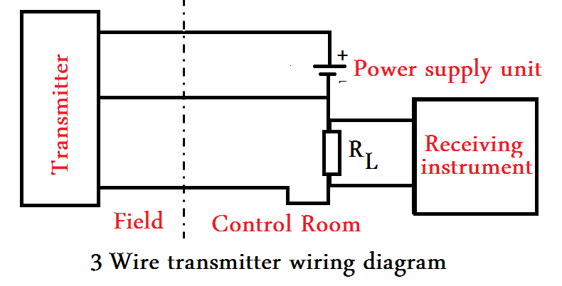
4 - 20mA Transmitter Wiring Types: 2 -Wire, 3 - Wire & 4 - Wire 4 - 20mA Process Transmitter Wiring Types: 2 -Wire, 3 - Wire, 4 - Wire ... The schematic diagram below shows the wire transmitter configuration: Three wire transmitters: Some transmitters require more power than the signal loop ( 4-20 mA. etc) can supply their internal circuitry. A DC common wire is run from the instrument to the transmitter.
4 Wire Proximity Switch Wiring Diagram Taiss 2pcs Lj12a3 4 Z Ax Inductive Proximity Sensor Detection Switch Npn Nc Dc 6v 36v 4mm Normally Close 6 Approach Online In Vietnam B073xdkm9s. Inductive Proximity Sensor Lj12a3 Photoelectric Capacity Solid State Relay Pcb Timer. Two Wire Inductive Proximity Sensors The Universal Donor. Wiring A Metal Detector With Npn Proximity Sensor On ...
Transmitter M400 FF 4-Wire - mt.com Transmitter M400 FF 4-Wire Reliable and Intelligent. ... M400 4wire G2 Wiring Diagram. Bus Communication Info . M400 4-wire FF Rev1 DD1 V1.0.00. Transmitter Configuration Tools (TCT) M400 G2 TCT V1.2.00. Software Tools . M400 4-wire FF PC demo. White Papers . Water Panel Transmitter Configuration.
4-Wire Current-Loop Sensor Transmitters - Planet Analog 4-wire sensor transmitter simplified block diagram. Unlike the 2- and 3-wire transmitter representations shown in Figure 2, the 4-wire circuit has separate paths for the power current and signal current. Also, the 4-wire receiver does not share a common return (GND) with the power supply. This allows for several new isolation schemes, including ...


0 Response to "43 4 wire transmitter wiring diagram"
Post a Comment