39 treadmill motor controller circuit diagram
ddmotorsystems.com › ElectricGoKartsHigh Torque Electric Go-Kart Motors, Speed Controllers & Kits This makes for very fun take-offs if your batteries, controller, and motor are up to it. What this means is that you have to think about electric power ratings differently. A Harbor Freight 6.5HP gas motor might be fun, but a 6.5HP electric motor is nearly 5000 watts (746W = 1HP) and will rip your face off and melt your batteries. Sweet. Proform Treadmill Wiring Diagram May 23, · Most treadmill motors are DC and have 4 wires. The 2 blue ones are the over temp breaker. The other 2 are connected to the brushes. Usually the connections are in series to prevent burning out the motor.treadmill wiring diagram Questions & Answers (with Pictures) - FixyaTreadmill motor wiring diagram
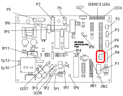
Understanding the MC-60 treadmill motor controller schematic I just did a quick look at the diagram and yes D10 + R9 "create" 12V for almost all electronics component in the circuit. Also D4 and D3 (D1 and D2 also) are the rectifier diodes for "Zener voltage regulator". D12 - I'm not so sure yet, but maybe this diode is to reduce the motor Inductive kick.

Treadmill motor controller circuit diagram
PDF PWM Circuit for MC-2100 Motor Controller Board - EL34 World PWM Circuit for MC-2100 Motor Controller Board For those interested in getting an MC-2100 motor controller board working, I offer this writeup on my experiences and ... And indeed while I was researching opto-isolators, schoolie proceeded to take a closer look at the control panel from a treadmill. I believe we came to the same conclusion at ... › dc-motor-speed3 Simple DC Motor Speed Controller Circuits Explained Aug 22, 2018 · A circuit which enables a user to linearly control the speed of a connected motor by rotating an attached potentiometer is called a motor speed controller circuit. 3 easy to build speed controller circuits for DC motors are presented here, one using MOSFET IRF540, second using IC 555 and the third concept with IC 556 featuring torque processing. treadmill motor controller circuit diagram Unsolved Problems (with ... Unanswered Questions for treadmill motor controller circuit diagram. Ad. 0 answers. The indicator panel does not light up, the treadmill will not start, nothing happens. The circuit breaker is fine and 120 volts is supplied to the motor control board. Read full answer.
Treadmill motor controller circuit diagram. 3 Simple DC Motor Speed Controller Circuits Explained Aug 22, 2018 · The following figure depicts the circuit diagram of a pulsed DC motor speed control. Here, T1, D1, D2, and C1 derive a sufficient DC supply from the mains AC supply. ... Treadmill Motor Speed Controller Circuit. Reply. T Brock says. January 24, 2022 at 6:32 am. Thank you! Reply. Christopher Gallagher says. November 14, 2021 at 9:54 am. Hello, Divine Treadmill Motor Control Board Schematic 300watt inverter circuit diagram. Treadmill motor control board schematic. Mc 2100 treadmill motor speed control circuit back to my main cnc page note. Sale price 139 50 139 50 save 35 50 treadmill motor control card yj 2256h yj 2256l for sole f63 f80 treadmill. I want to control it s speed from zero to max by powering it from 220v ac power grid. Treadmill Motor Wiring Diagram & Testing Procedures When a treadmill component must be replaced go to this section and follow the step by step procedures required to remove and replace the component. Scratch a line on the motor pan where the motor bracket sits and set the dc motor bracket back to that spot before testing belt 230j8 tension. A basic block level diagram is explained, followed by ... High Torque Electric Go-Kart Motors, Speed Controllers & Kits D&D Motor Systems is the premier go kart electric motor manufacturer in the U.S. for electric go karts.Our electric go kart motors offer higher performance than the pancake motors that are out there. Our electric go kart motor has: higher torque, better thermal capabilities and a competitive price.In addition, we offer a U.S. made go cart speed controller to go with our go kart motors.
Treadmill motor wiring diagram, anyone??? - Google Groups The schematic in the drop box that I mentioned is for the GE controller. I have both the GE controller and the GE DC treadmill motor. This motor has a 5/8" shaft about 1-1/2" long and keyed 3/16" I... Lieo Power First PF906 Treadmill Controller Circuit ... - Instructables LED 3 (red) lights when either opto-couplers FR3 or FR4 are driven by the treadmill controller board ; LED 4 (red) lights when the treadmill controller board drives the power relay to close. All the above is shown on the schematic diagram I drew of the critical parts of the motor controller board. Treadmill Motor Wiring Diagram - Collection Following diagrams is fairly simple, but making use of it inside the scope of how the device operates is a new different matter. The best advice is not necessarily only look from the diagram, yet understand how the components operate when in use. Treadmill Motor Wiring Diagram Source: ts1.mm.bing.net Stunning Treadmill Motor Speed Control Circuit Diagram The Post Explains A Simple Treadmill Motor Speed Controller Circuit Which Has Zero To Maximum Co Electronic Projects 2004 Nissan Sentra 1.8 Fuse Box Diagram 5 Flat Trailer Wiring Mc2100 Treadmill Motor Control Circuit And Wiring At Diagram Schede Ceiling Fan 3 Way Switch L293d Driver Board Pin
› H-Bridge-PWM-DC-Motor-DriverH Bridge PWM DC Motor Driver - Instructables P1 is a 5 pins XH connector that is used to apply the chips’ supply and control signals to the board. K1 is a KF45 power connector that is used to connect the motor and motor’s supply wires to the board. [B] PCB Layout Figure 3 shows the PCB layout of the H-Bridge DC motor driver. It is a 2 layers PCB board and all component packages are ... News Archives | Hollywood.com Travel through time by exploring Hollywood.com's entertainment news archives, with 30+ years of entertainment news content. MC2100LTS-30 circuit diagram needed - All About Circuits Steps taken: 1. Unplug from wall outlet, open motor cover, check all terminals and headers, verified that they are seated correctly. Removed motor connections from control board, removed motor, pulled & cleaned brushes, visually inspected commutator. Reinstalled brushes, reinstalled motor and motor connections to control board. Proteus simulation based avr projects - ATMega32 AVR AT89C51 L293D Motor Control Circuit Operation, Our project name and the name suggests, the treadmill is the motor control is required. When designing this project, I saw fit to use… AT89C51 5X7 LED MATRIX APPLICATION
Treadmill Motor Replacement Wiring Diagram - Complete Wiring Schemas
MC-2100 Treadmill Motor speed control circuit - EL34 World The Treadmill DC motor - Here's a shot of the MC-2100 board The Black and White wires on the right side are the AC power cord wires The black and red wires in the middle are the Motor wires (A- and A+) Red is A+ Black is A- Do not reverse your motor wires Some motors are designed to turn in a specific direction My motor turns clockwise

The Wood Knack: Variable speed lathe using a DC treadmill motor
Treadmill Dcmd57 Control Board Wiring Diagram - schematron.org /E//E Display Board Wiring Connection Diagram. Soft Keys . The PWM signal emits the drive board motor voltage to control motor speed. Choose the tape to the treadmill, available in different sizes. please contact us by sending an email to info@schematron.org specifications of its original circuit board.

21 Treadmill Motor Controller Circuit Diagram - Wiring Diagram Niche
Controlling 3 Phase Induction Motor Using VFD And PLC Dec 27, 2018 · An electrical motor is an electromechanical device that converts electrical energy into mechanical energy. In the case of 3-phase AC operation, the most-widely-used motor is the 3 Phase Induction Motor as this type of motor does not require any starting device, being a self-starting motor. Fig. 1: Entire system layout Fig. 2: Block diagram of a ...

treadmill motor controller problem? | All About Circuits
How to wire up and use a treadmill motor quick run down, DIY ... - YouTube direct responce to mrpete222, here is a Really quick video of how to use a treadmill motor, and the basic functions of the control board. what to cut what to...

Treadmill Motor Speed Controller problems! | Page 2 | All About Circuits
Treadmill Motor Controller Schematic - schemaeasy.com The drivers of a brushless motor controller schematic act as intermediaries Shown below is a modified dimmer switch circuit design which can be effectively used for regulating a V treadmill motor from zero to max: Please make sure to use a non-polar capacitor for the one shown between the bridge rectifier.

Treadmill Motor Replacement Wiring Diagram - Complete Wiring Schemas
my.alldata.com › ColRef › Collision_ReferenceCollision Reference Outputs control the operation of the ABS solenoids in the modulator, and the pump and motor assembly on systems that have a pump. Controller (Brakes) A device that uses a variable resistor to regulate current flow to an electric brake friction assembly based on hand, foot, hydraulic, or air pressure.

Wiring a Treadmill Motor for a Wood Lathe
wiring-diagram-smooth0001 - Treadmill Doctor Wiring Diagram Power cord yellow/Green 3 connect with the ground Power cord blue 2 connect with switch 6 (Input voltage 110V-120V) Power corder brown 1 connect with fuse red 4 (Input voltage 110V-120V) Fuse red connect with switch (Input voltage 110V-120V) Connect switch 8 and controller CAN with a red wire (Input voltage 110V-120V)
Motor Controller Comm Bad Error On LifeFitness 9700HR, 9100 And
271 How to Repair Circuit for TreadMill - YouTube To Watch in Urdu Hindi to Repair Circuit for TreadMill Variable Frequency Drive (VFD) circuit for TreadMill - Circuit Diagra...

treadmill motor controller problem? | All About Circuits
make a simple treadmill circuit - Forum for Electronics ya i need to make simple dc motor control circuit with speed control (pot) to drive treadmill the out put voltage is should be 20v to 180v with minimum 8 amps to control the speed acuration much better if you can use magnetic or opto sensers May 27, 2012 #7 ctownsend Advanced Member level 2 Joined Nov 27, 2004 Messages 575 Helped 93 Reputation 188

MC-2100 Treadmill Motor speed control circuit
Treadmill Dcmd57 Control Board Wiring Diagram Mar 01, · 3) tight the key panel flexible cable vs display board 4) then connector display board vs lower board.5) test the main motor controller bOARDEC for 5+vdc, to display wiringall.com the block diagram how the main motor controller has 90% aprox for control functions of any wiringall.comely. May 23, · Treadmill motor wiring diagram, anyone???

Brushless motor controller Schematic « Brushless motors, 3Phase ...
› electronics-projectsControlling 3 Phase Induction Motor Using VFD And PLC Dec 27, 2018 · An electrical motor is an electromechanical device that converts electrical energy into mechanical energy. In the case of 3-phase AC operation, the most-widely-used motor is the 3 Phase Induction Motor as this type of motor does not require any starting device, being a self-starting motor. Fig. 1: Entire system layout Fig. 2: Block diagram of a ...
Zero Emission Vehicles Australia
Use a Treadmill DC Drive Motor and PWM Speed Controller for Powering ... Step 1: Types of Treadmill Motors I have seen 3 types of motors. DC Permanent Magnet with PWM controller (Great for torque at all speeds).2 wires to the motor (Usually). DC motor with Armature-voltage DC Motor Control. (Great for torque at all speeds).4 wires to the motor. 2 run to the shunt-field current , 2 run to the armature.
Treadmill Dcmd57 Control Board Wiring Diagram
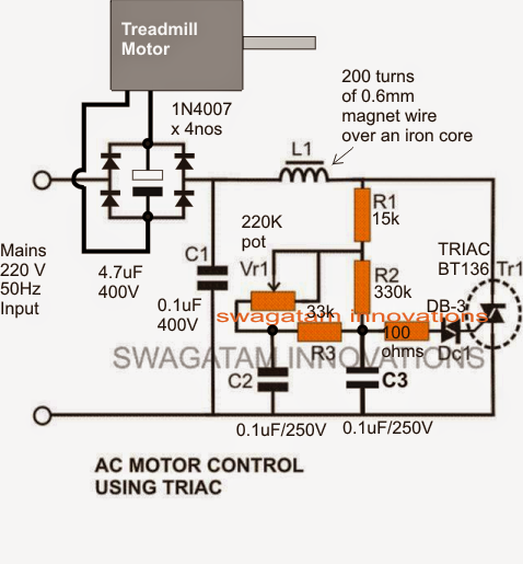
Treadmill Motor Controller Circuit Diagram: A Conclusive Guide Simplified circuit diagram for treadmill motor controller To enable treadmill motor control, include a 1K potentiometer across pin 5 of the second IC. Also, add another to the ground wires on the same pin. Alternatively, you can add a pot parallel to C3. Additionally, the 10K pot works as the motor speed sensor.
21 Treadmill Motor Controller Circuit Diagram - Wiring Diagram Niche
DC treadmill motor wiring info needed | The Hobby-Machinist Wire harness from the operator panel terminates with a flat connector on the motor panel board with wire colors L to R of brown,blue,yellow,green,red black,orange and grey. They other red and black wire pair shown in picture 100-0770 is from the speed pickup. If these photos load you will see all I have so far.

11+ Treadmill Motor Controller Circuit Diagram | Robhosking Diagram
NeuroMechFly, a neuromechanical model of adult Drosophila May 11, 2022 · NeuroMechFly enables simulations of adult Drosophila melanogaster. The platform combines a biomechanical representation of the fly body, models of the muscles, a neural controller and a physics ...

York t781 treadmill service manual
› treadmill-motor-speedTreadmill Motor Speed Controller Circuit Shown below is a modified dimmer switch circuit design which can be effectively used for regulating a 180 V treadmill motor from zero to max: Please make sure to use a non-polar capacitor for the one shown between the bridge rectifier. Use the following type, 10 in parallel
0 Response to "39 treadmill motor controller circuit diagram"
Post a Comment